Table of Contents
Advertisement
Advertisement
Table of Contents

Related Manuals for Art PRO MPA II


Summary of Contents for Art PRO MPA II
- Page 1 PRO MPA II ™ ART PRO MPA II Microphone Preamplifier USER’S GUIDE...
- Page 2 IMPORTANT SAFETY INSTRUCTIONS – READ FIRST This symbol, wherever it appears, This symbol, wherever it appears, alerts alerts you to the presence of uninsulated you to important operating and maintenance dangerous voltage inside the enclosure. Voltage instructions in the accompanying literature. that may be sufficient to constitute a risk of shock.
-
Page 3: Table Of Contents
Balanced Inputs ............................8 Balanced Outputs ............................. 8 PRO MPA II OPERATING INSTRUCTIONS ................9 Obtaining the best noise performance with the PRO MPA II..............9 Adjusting the Input Impedance ......................... 9 Setting the Tube Plate Voltage ....................... 10 Using the Mid/Side mode........................11 WARRANTY INFORMATION.................... -
Page 4: Features/General
Automatically switches to the instrument input when you plug in • The signal path of PRO MPA II consists of a discrete class A microphone pre-amp followed by a Low Cut Filter, a balanced differential tube circuit with a 20dB Gain switch and then the phase switch. The Mid/Side Matrix switch sums the adjacent channel to decode left and right information following the gain switch function and before the output level control. - Page 5 Figure 1 – Block Diagram...
-
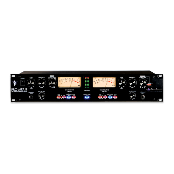
Page 6: Front Panel Connections And Controls
Both the microphone and instrument inputs are optimized for their respective sources as far as signal levels and noise performance. Running most of the gain on the input generally provides the best performance of the PRO MPA II . Refer to the section titled “Obtaining the best noise performance... -
Page 7: Input Impedance Control
PRO MPA II ” for more detailed instructions on setting the Input Gain control for the best results. Input Impedance control This knob controls the Mic/line input amplifier impedance. This function allows variable voicing of any microphone. Refer to the application section titled “Adjusting the Input Impedance” for more information on making the most of this function. -
Page 8: Phantom Switch
The amount of headroom is adjusted by using the Gain switch and the input Gain control. The PRO MPA II takes about 10-30 seconds to smoothly transition from one mode to the other. There is a slight increase in gain in the “High” plate voltage mode. -
Page 9: Mid/Side Matrix Switch
In the “Normal” (OUT) position, the tube distortion gradually rises until it smoothly clips. The tube is run almost completely open-loop in this mode, providing a musical tube “crunch” when overdriven with a natural recovery from clipping. The tube section can be more easily overdriven when the gain switch is in. -
Page 10: Switch (Rear Panel)
The +4/-10 switch is used to set the output level of the PRO MPA II for the appropriate system levels. This feature allows you to match 0 VU on the meters of the PRO MPA II and your mixer or other equipment. -
Page 11: Rear Panel Connections
Balanced Inputs The PRO MPA II ’s XLR connectors follow the AES standard of Pin 1 = Ground, Pin 2 = Hot (+), Pin 3 = Cold (-). The Balanced inputs have an input impedance that is variable from 150 to 3K Ohms via the front panel control. -
Page 12: Pro Mpa Ii Operating Instructions
PRO MPA II OPERATING INSTRUCTIONS Obtaining the best noise performance with the PRO MPA II Start by turning down the Input Gain knob and centering the Analog Output knob. Use the analog meter to view the operating level by depressing the switch under the center of the analog meter. The meter will now indicate how much tube headroom there is. -
Page 13: Setting The Tube Plate Voltage
Setting the Tube Plate Voltage The PRO MPA II allows the user select between one of two vastly different tube bias and power supply levels. The transition between either setting is smooth and quiet and the gain variation is minimal. -
Page 14: Using The Mid/Side Mode
Using the Mid/Side mode The PRO MPA II is designed for stereo operation using the Mid/Side switch and two microphones. One of the mics needs to have a figure-8 pickup pattern. Start by aligning two mics 90 degrees apart. Connect the mic facing front (with an omni-directional or cardiod pickup pattern) to CH1. -
Page 15: Warranty Information
WARRANTY INFORMATION Limited Warranty Applied Research and Technology will provide warranty and service for this unit in accordance with the following warrants: Applied Research and Technology (A R T) warrants to the original purchaser that this product and the components thereof will be free from defects in workmanship and materials for a pe- riod of three years from the date of purchase. -
Page 16: Service
2) If you believe the ART unit is at fault, go to www.artproaudio.com. You may contact Cus- tomer Service for more assistance, or directly request a Return Authorization for service in the “resources”... -
Page 17: Pro Mpa Ii Specifications
PRO MPA II SPECIFICATIONS Frequency Response ......15Hz to 48 kHz (+0, -1dB) @ normal plate voltage 15Hz to 120 kHz (+0, -1dB) @ high plate voltage Dynamic range:........>110dB (“A” weighted) CMRR: ..........>90dB THD: ............. <0.005% (typical) Equivalent Input Noise: ......-129dBu (XLR, “A” weighted) Maximum Input Level: ...... - Page 18 NOTES:...
- Page 20 E-mail: cserve@artproaudio.com PRO MPA II – Microphone Preamplifier 214-5004-201h...
Need help?
Do you have a question about the PRO MPA II and is the answer not in the manual?
Questions and answers