Table of Contents
Advertisement
Advertisement
Table of Contents

Related Manuals for Art DIGITAL MPA II


Summary of Contents for Art DIGITAL MPA II
- Page 1 DIGITAL MPA II™ ART DIGITAL MPA II™ Microphone Preamplifier USER’S GUIDE...
- Page 2 IMPORTANT SAFETY INSTRUCTIONS – READ FIRST This symbol, wherever it appears, This symbol, wherever it appears, alerts alerts you to the presence of uninsulated you to important operating and maintenance dangerous voltage inside the enclosure. Voltage instructions in the accompanying literature. that may be sufficient to constitute a risk of shock.
-
Page 3: Table Of Contents
S/PDIF output ............................13 AES/EBU output ............................. 13 DIGITAL MPA II OPERATING INSTRUCTIONS..............14 Obtaining the best noise performance with the DIGITAL MPA II............14 Adjusting the Input Impedance ....................... 14 Obtaining the perfect digital level setting ....................15 Setting the Tube Plate Voltage ....................... 16 Using the Mid/Side mode........................ -
Page 4: General Information
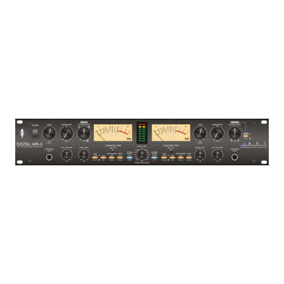
Building upon the quality and success of great sounding products like the Pro MPA and MPA GOLD, ART engineers set out to develop the next generation of professional microphone preamplifier. The DIGITAL MPA II is the culmination of years of research and development, and sets a new standard for quality and value. - Page 5 The signal path of the DIGITAL MPA II consists of a discrete class A microphone pre-amp followed by a Low Cut Filter, a balanced differential tube circuit with a 20dB Gain switch and then the phase switch. At this point the signal passes to both the analog output and the Insert jacks. The insert jacks allow processing of the signal before its’...
-
Page 6: Front Panel Connections And Controls
Both the microphone and instrument inputs are optimized for their respective sources as far as signal levels and noise performance. Running most of the gain on the input generally provides the best performance of the DIGITAL MPA II. Refer to the section titled “Obtaining the best noise performance... -
Page 7: Input Impedance Control
DIGITAL MPA II for more detailed instructions on setting the Input Gain control for the best results. Input Impedance control This knob controls the Mic/line input amplifier impedance. This function allows variable voicing of any microphone. Refer to the application section titled “Adjusting the Input Impedance” for more information on making the most of this function. -
Page 8: Phantom Switch
The amount of headroom is adjusted by using the Gain switch and the input Gain control. The DIGITAL MPA II takes about 10-30 seconds to smoothly transition from one mode to the other. There is a slight increase in gain in the “High” plate voltage mode. -
Page 9: Mid/Side Switch
In the “Normal” (OUT) position, the tube distortion gradually rises until it smoothly clips. The tube is run almost completely open-loop in this mode, providing a musical tube “crunch” when overdriven with a natural recovery from clipping. The tube section can be more easily overdriven when the gain switch is in. -
Page 10: Switch (Rear Panel)
The +4/-10 switch is used to set the output level of the DIGITAL MPA II for the appropriate system levels. This feature allows you to match 0 VU on the meters of the DIGITAL MPA II and your mixer or other equipment. -
Page 11: Sample Rate Control
Sample Rate control The Sample rate knob determines both the output sample rate of the DIGITAL MPA II as well as the dither. You can select either AES/EBU (pro) format or S/PDIF (consumer) data format. -
Page 12: Dither Settings
2-channel mode (TOSLINK). When ADAT output is active, The left channel of the DIGITAL MPA II is output on CH1, the right channel of the DIGITAL MPA II is CH2, and the rest of the channels consist of data received from the ADAT Input jack. -
Page 13: Front Panel Connections
When you plug into this jack it DISABLES the balanced input on the rear of the unit. This feature allows you to keep the rear input patched in, and use the instrument input to switch to a different source. The instrument input allows the DIGITAL MPA II to serve as a great DI device as well. -
Page 14: Rear Panel Connections
Balanced Inputs The DIGITAL MPA II’s XLR connectors follow the AES standard of Pin 1 = Ground, Pin 2 = Hot (+), Pin 3 = Cold (-). The Balanced inputs have an input impedance that is variable from 150 to 3K Ohms via the front panel control. -
Page 15: Insert Jacks
RMS) Wordclock jacks The DIGITAL MPA II offers Wordclock input on a BNC connectors. A 5V logic level signal is required to drive the digital clock circuitry. Both BNC connectors are tied together allowing you to loop word- clock through the DIGITAL MPA II saving cabling complexity. -
Page 16: S/Pdif Output
S/PDIF spec. AES/EBU output The AES/EBU output of the DIGITAL MPA II is a 5V p-p signal with a 110 Ohm impedance. This cannon connector is driven by the same drive circuitry and isolation transformer and as the S/PDIF... -
Page 17: Digital Mpa Ii Operating Instructions
DIGITAL MPA II OPERATING INSTRUCTIONS Obtaining the best noise performance with the DIGITAL MPA II Start by turning down the Input Gain knob and centering the Analog Output knob. Set the +20dB switch , Plate Voltage switch and the Stereo/ Dual mode switch in the "out" position. The analog VU meter will now indicate how much tube headroom there is. -
Page 18: Obtaining The Perfect Digital Level Setting
DIGITAL MPA II front panel. If you wish to operate the Digital MPA II in the "High" plate voltage mode, reduce the Output knob by 5dB to compen- sate for the difference in tube headroom/gain. You can also use the Digital meter to monitor the tube headroom in this... -
Page 19: Setting The Tube Plate Voltage
Setting the Tube Plate Voltage The DIGITAL MPA II allows the user select between one of two vastly different tube bias and power supply levels. The transition between either setting is smooth and quiet and the gain variation is minimal. -
Page 20: Using The Mid/Side Mode
Using the Mid/Side mode The DIGITAL MPA II is designed for stereo operation using the Mid/Side switch and two micro- phones. One of the mics needs to have a figure-8 pickup pattern. Start by aligning two mics 90 degrees apart. Connect the mic facing front (with an omni-directional or cardiod pickup pattern) to CH1. -
Page 21: Warranty Information
WARRANTY INFORMATION Limited Warranty Applied Research and Technology will provide warranty and service for this unit in accordance with the following warrants: Applied Research and Technology (A R T) warrants to the original purchaser that this product and the components thereof will be free from defects in workmanship and materials for a pe- riod of three years from the date of purchase. -
Page 22: Service
2) If you believe the ART unit is at fault, go to www.artproaudio.com. You may contact Cus- tomer Service for more assistance, or directly request a Return Authorization for service in the “resources”... -
Page 23: Digital Mpa Ii Specifications
DIGITAL MPA II SPECIFICATIONS Analog Section: Frequency Response........15Hz to 48 kHz (+0, -1dB) @ normal plate voltage 15Hz to 120 kHz (+0, -1dB) @ high plate voltage Dynamic range:........... >110dB (“A” weighted) CMRR: ............>90dB THD: ............<0.005% (typical) Equivalent Input Noise:....... - Page 24 E-mail: cserve@artproaudio.com DIGITAL MPA II 216-5004-201h...
Need help?
Do you have a question about the DIGITAL MPA II and is the answer not in the manual?
Questions and answers