Table of Contents
Advertisement
Advertisement
Table of Contents

Related Manuals for Art PRO CHANNEL II


Summary of Contents for Art PRO CHANNEL II
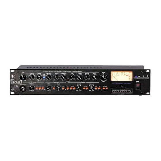
- Page 1 PRO CHANNEL II TUBE PREAMP - OPTO COMPRESSOR - EQ SERVICE MANUAL...
- Page 2 IMPORTANT SAFETY INSTRUCTIONS – READ FIRST This symbol, wherever it appears, This symbol, wherever it appears, alerts alerts you to the presence of uninsulated you to important operating and maintenance dangerous voltage inside the enclosure. Voltage instructions in the accompanying literature. that may be sufficient to constitute a risk of shock.
-
Page 3: Table Of Contents
COMP OUT Jack....................................12 EQ IN Jack ......................................12 OUTPUT Jacks ....................................12 OUTPUT LEVEL Switch ..................................12 APPLICATIONS..................................13 Bypassing Components Of The Pro Channel II............................ 13 Optimizing The Preamp For Lowest Noise............................13 WARRANTY INFORMATION............................... 14 SERVICE....................................27 SPECIFICATIONS ................................28 LIST OF FIGURES FIGURE 1 –... - Page 4 INTRODUCTION The ART Pro Channel II is the answer to your recording and computer audio interface needs. Our second-generation discrete Class-A microphone preamp provides clean quiet gain while maintaining incredible transparency. A powerful dynamics processor subtly controls transients and noise of the most demanding sources.
-
Page 5: Ac Power Hookup
INSTALLATION The ART Pro Channel II may be used in a wide variety of applications and environments. In a rack- mountable, all-steel enclosure, the unit is designed for continuous professional use. Mounting location is not critical, however for greater performance reliability we recommend that you not place the unit on top of power amps, or other sources of heat and/or strong magnetic fields. -
Page 6: Front Panel Controls And Jacks
Impedance Control This knob sets the load impedance at the rear panel XLR input of the Pro Channel II. Use the IMPEDANCE CONTROL to subtly tune the sound of your microphone. Various microphones will change their sound at differing load impedances. -
Page 7: Gain Switch
The switch safely applies +48Volt phantom power to the XLR input. Use phantom power only when the microphone that you are using requires it. Doing so will extend the life of the Pro Channel II as well as reducing the possibility of shock hazard. -
Page 8: Tube Voltage Switch
Tube Voltage Switch The vacuum tube preamp section can be adjusted to run at two different plate voltages. Refer to Figure 1 for the location of the switch. Choose the “NORMAL” setting for adding warmth to the input signal. This setting has an increased amount of tube saturation at higher signal levels. -
Page 9: Compressor Controls
Threshold Control This control sets the level, above which the Compressor in the Pro Channel II starts to act on the input signal. As the control is turned clockwise, more input signal is required to begin reducing gain. -
Page 10: Attack Control
Attack Control The ATTACK control sets the time it takes the Compressor/Limiter to respond to increases in signal level (by reducing gain). You can use this control to shape the “front end” of the dynamics envelope. One example is to listen to a snare hit and adjust the attack control. A short attack makes the snare sound “thin”. -
Page 11: Gain Reduction Led Meter
Semi-Parametric EQ The ART Pro Channel II offers a four-band semi-parametric equalizer. The entire EQ can be bypassed with a single switch. Each band has + 12dB of control range. The High and Low EQ bands are shelving type with a switch selectable turnover point. -
Page 12: Eq Bypass Switch
This switch allows you to instantly set the EQ completely flat without loosing the current EQ settings. CLIP LED This LED indicates clipping in any section of the Pro Channel II. You can isolate the source of the clipping to the INPUT section by reducing the Preamp output, if the clipping LED remains lit. -
Page 13: Output Meters
Output Meters The ART Pro Channel II provides both analog VU and LED level meters. The analog VU meter displays the signal level various points of the processor depending on the setting of the VU Meter Switches. “0” VU on the analog VU meter corresponds to +4dBu on the balanced output. -
Page 14: Rear Panel Connections
This 1/4-inch T/S unbalanced jack provides a direct signal from the microphone preamplifier, ahead of the EQ and dynamics processors. This output can be used in conjunction with the INSERT INPUT jack to insert external signal processors between the main preamp section and the compressor of the Pro Channel II. -
Page 15: Comp In Jack
Channel II. OUTPUT Jacks The analog output of the Pro Channel II is available on both a 1/4-inch unbalanced jack and an XLR balanced jack. The XLR output is active balanced, and will adjust to balanced or unbalanced termination without gain change. -
Page 16: Optimizing The Preamp For Lowest Noise
Optimizing The Preamp For Lowest Noise The preamp of the ART Pro Channel II can be optimized for low noise by combining use of the PAD and Input GAIN control for mic and line level signals. NOTE: The PAD control has no effect on the INSTRUMENT INPUT (Front panel 1/4-inch input of the INPUT combo jack). - Page 17 Repair Parts ART Part # Value Description Footprint QTY LOCATION POTENTIOMETER SECTION VR16-HI-MID, 1001027215 100K 20C POT-16DUAL-H Pot, Dual Element VR17-LO-MID POT - Single Control / VR14-ATTACK 1001027214 100K A POT-16SGL-H Trimmer TIME POT - Single Control / VR5-RATIO, 1001027213...
- Page 18 ART Part # Value Description Footprint QTY LOCATION MISC SECTION Vactrol, LED-LDR, Single 1001043101 VTL5C2 VACTROL Element VCT1 215AINLAY Inlay gain reduction meter MECHANICAL SECTION 1005269103 SWT power switch swt rocker pwr spst 22V-0-22V 120/240V 1001510101 TRANSFORMER, TOROID TD00785 TAIWAN...
- Page 19 Full Bill of Materials ART Part # Value Description Footprint QTY LOCATION RADIAL CAPACITOR SECTION 1001037116 .001uF RADIAL0.2 Capacitor, Film / Ceramic C25,C60 1001037101 0.0068 RADIAL0.2 Capacitor, Film / Ceramic C41, C51 1001037105 0.01 RADIAL0.2 Capacitor, Film / Ceramic C50, C55 1001037110 0.068...
- Page 20 ART Part # Value Description Footprint QTY LOCATION 1001005120 680pF CAP-AXIAL Capacitor, Film / Ceramic AXIAL RESISTOR SECTION Resistor, Carbon Film, R6, R7, R26, R27, R28, 1001001301 1.00K AXIAL0.4 R42, R172, R179 Resistor, Carbon Film, 1001002176 1.5K AXIAL0.4 R183 Resistor, Carbon Film, 1001002191 AXIAL0.4...
- Page 21 ART Part # Value Description Footprint QTY LOCATION R4, R5, R36, R53, R68, R72, R73, R74, R82, R94, R130, R135, R151, R187, R211, Resistor, Carbon Film, R218, R221, R237, 1001001334 2.21K AXIAL0.4 R238, R239, R240 R38, R71, R77, R122, R143,...
- Page 22 ART Part # Value Description Footprint QTY LOCATION Resistor, Carbon Film, R2, R12, R13, R16, 1001002163 499 Ohms AXIAL0.4 R17, R20 Resistor, Carbon Film, R117, R123, R133, 1001002185 5.1M AXIAL0.4 R139, R161, R225 Resistor, Carbon Film, 1001001373 5.62K AXIAL0.4 R190...
- Page 23 ART Part # Value Description Footprint QTY LOCATION DIODE SECTION D7, D9, D10, D26, D27, D28, D29, D30, D31, D32, D33, D34, D43, Diode - Signal or Power D44, D200, D201, D202, D203 1001098101 1N4004 DIODE0.5 Rectifier D2, D3, D4, D8, D11,...
- Page 24 ART Part # Value Description Footprint QTY LOCATION LED - Single, Various 1001132102 BLUE LED-T1 PCB mount LED4 LED1, LED2, LED3, LED5, LED7, LED8, LED9, LED10, LED11, LED - Single, Various LED12, LED13, LED14, 1001031119 ORANGE LED-T1 PCB mount LED15, LED16...
- Page 25 ART Part # Value Description Footprint QTY LOCATION MISC SECTION Vactrol, LED- LDR, Single Element 1001043101 VTL5C2 VACTROL VCT1 Faston Tab - P1, P2, P3, P4, P5, P6, 1005262101 TAB.250 TAB.250 Male PCB .250 Pad for Wire Jumpers - 10...
- Page 26 ART Part # Value Description Footprint QTY LOCATION 1005216104 BKT BRACKET RT ANGLE 4-40X2 LEDS/CHASSIS STANDOFF, PCB-PCB, 1.2", THREADED 4-40 PCB/LEDS CHASSIS, 1005032119 FAS SCR 4-40X1/4 PH PN HD BLK SCREWS Swages 100-5027-122 FAS SCR 6-32X3/8 PH PN HD BLK...
- Page 27 SW1B wc+dB Norm SW1A SW3B SW3A Norm Invert...
- Page 28 AC LINE INPUT VR16A 100K 20C DUAL VR17A 100K 20C DUAL...
-
Page 29: Warranty Information
WARRANTY INFORMATION Limited Warranty Applied Research and Technology will provide warranty and service for this unit in accordance with the following warrants: Applied Research and Technology, (A R T) warrants to the original purchaser that this product and the components thereof will be free from defects in workmanship and materials for a period of three years from the date of purchase. - Page 30 You may want to consult with your dealer for assistance in troubleshooting or testing your particular configuration. 2. If you believe that the ART unit is at fault, go to www.artproaudio.com. 3. Select “Support”, then “Return Authorization Request” to request a return authorization number.
- Page 31 Note: 0 dBu = 0.775 VRMS, 0 dBV = 1 VRMS ART maintains a policy of constant product improvement. ART reserves the right to make changes in design, or make additions to, or improvements upon, this product without any obligation to install same on products previously manufactured. Therefore, specifications are subject to change without...
- Page 32 E-mail: support@artproaudio.com © 2020 Applied Research & Technology Pro Channel II 215a-5004-105 TUBE PREAMP - OPTO COMPRESSOR - EQ...
Need help?
Do you have a question about the PRO CHANNEL II and is the answer not in the manual?
Questions and answers