Advertisement
Quick Links
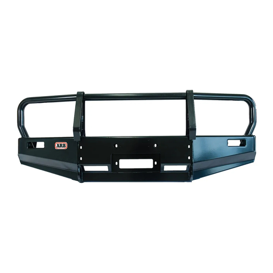
ARB DELUXE BULL BAR TO SUIT
MAZDA BRAVO & FORD COURIER 1999 On
Part No's 32/3440050 without flares, Part No's 32/3440060 with flares
WHEN INSTALLED IN ACCORDANCE WITH THESE INSTRUCTIONS, THE FRONT
PROTECTION BAR DOES NOT AFFECT OPERATION OF THE SRS AIRBAG.
TAKE NOTE OF THE FOLLOWING:
• THIS PRODUCT MUST BE INSTALLED EXACTLY AS PER THESE INSTRUCTIONS USING
ONLY THE HARDWARE SUPPLIED.
• DO NOT USE THIS PRODUCT FOR ANY VEHICLE MAKE OR MODEL, OTHER THAN
THOSE SPECIFIED BY ARB.
• DO NOT REMOVE LABELS FROM THIS BULL BAR.
THIS PRODUCT OR ITS FIXING MUST NOT BE MODIFIED IN ANY WAY.
07-05-03
If you have any queries regarding the installation of this product please contact the distributor from whom it was purchased, or alternatively the ARB office in your state.
Head Office – ARB corporation Ltd VIC: 42-44 Garden Street, Kilsyth, Victoria, 3137 Tel: (03) 9761 6622 Fax: (03) 9761 6807
WA:(08) 9244 3553 NSW: (02) 9821 3633 ACT: (02) 6280 7475 SA: (08) 8244 5001 QLD: (07) 3872 3872 NT: (08) 8947 2262 TAS: (03) 6331 4190
WARNING
FOR VEHICLES EQUIPPED WITH SRS AIRBAG
Page 1 of 6
3783037
Advertisement

Related Manuals for ARB DELUXE BULL BAR


Summary of Contents for ARB DELUXE BULL BAR
- Page 1 3783037 If you have any queries regarding the installation of this product please contact the distributor from whom it was purchased, or alternatively the ARB office in your state. Head Office – ARB corporation Ltd VIC: 42-44 Garden Street, Kilsyth, Victoria, 3137 Tel: (03) 9761 6622 Fax: (03) 9761 6807...
- Page 2 6151132 M8 FLANGE NUT 4581044 M8 FLAT WASHER 3500200 BUFFER 6151132 M8 FLANGE NUT 3500080 ARB INDICATOR KIT (CONTAINS LEFT AND RIGHT) FOR THE WINCH BULL BARS ONLY PART No DESCRIPTION 8-9000lb WINCH 4581040 M10 FLAT WASHER NUMBER PLATE 3751789...
- Page 3 FITTING PROCEDURE 1. Remove bumper bar and tow hooks from the vehicle. 2. Fit the left and right hand impact absorbers to the top of the chassis rails using the M12 bolts, spring washers and flat washers supplied. Finger tighten only. (Refer to diagram 1) ACCESS TO TOP BOLTS IS VIA DIAGRAM 1 THE ENGINE COMPARTMENT...
- Page 4 9. WINCH BARS: FITTING THE 8000 OR 9,000lb WINCH A. Remove the cover of the control box, disconnect the two heavy short black cables and the heavy short red cable and replace with the corresponding cables supplied. Replace the cover; fit the control box to the control box bracket using the two 1/4”...
- Page 5 IAGRAM 5 Original hole 25.0mm New hole BULL BAR TO VEHICLE FITMENT: 9. Lift the bull bar onto the impact absorbers with the braces on the outside of the bull bar and loosely bolt in place using the M10 x 30mm bolts, washers and spring washers. (Refer to Diagram 6). DIAGRAM 6 Two bolts on the outside and one on the inside.
- Page 6 12. Connect the bull bar turn signal indicator looms to the existing turn signal indicator loom with the Scotchloks supplied and test to ensure they function correctly. 13. Using a pair of tin snips, trim back the plastic inner guard and metal panel that sit below the line of the bull bar. (Refer to diagram 8) DIAGRAM 8 13.
Need help?
Do you have a question about the DELUXE BULL BAR and is the answer not in the manual?
Questions and answers