Table of Contents
Advertisement
Quick Links
INSTRUCTIONS FOR SAFE OPERATION AND MAINTENANCE
Understand manual before use. Operation of this device without understanding the manual and
WARNING
receiving proper training is a misuse of this equipment. Obtain safety information at www.tft com/
serial-number
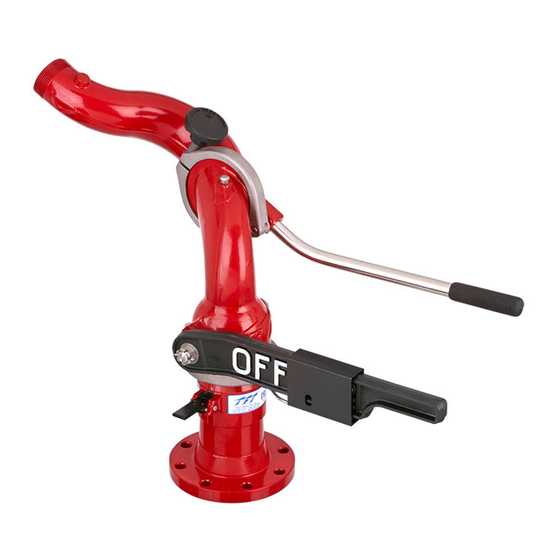
This instruction manual is intended to familiarize fi refi ghters and maintenance personnel with the operation, servicing, and safety
procedures associated with the PROTECTOR Station Monitor. This manual should be kept available to all operating and maintenance
personnel.
Shown with optional valve.
TASK FORCE TIPS, INC.
MADE IN USA • www.tft.com
©Copyright Task Force Tips, Inc. 1999-2017
MANUAL: PROTECTOR
Maximum fl ow is
1250 GPM (4800 L/MIN)
Maximum inlet pressure is
250 PSI (17 BAR)
3701 Innovation Way, Valparaiso, IN 46383-9327 USA
STATION MONITOR
800-348-2686 • 219-462-6161 • Fax 219-464-7155
LIZ-010 December 26, 2017 Rev12
Advertisement
Table of Contents

Related Manuals for Task Force Tips PROTECTOR


Summary of Contents for Task Force Tips PROTECTOR
- Page 1 This instruction manual is intended to familiarize fi refi ghters and maintenance personnel with the operation, servicing, and safety procedures associated with the PROTECTOR Station Monitor. This manual should be kept available to all operating and maintenance personnel. Shown with optional valve.
- Page 2 6. Failure to follow these guidelines may result in death, burns or other severe injury. Fire and Emergency Manufacturers and Service Association FEMSA P.O. Box 147, Lynnfi eld, MA 01940 • www.FEMSA.org ©Copyright Task Force Tips, Inc. 1999-2017 LIZ-010 December 26, 2017 Rev12...
-
Page 3: Table Of Contents
9.0 MAINTENANCE ..............................19 9.1 LOWER SEAL AND VALVE SEAT 9.2 UPPER SWIVEL SEAL AND SWIVEL INSERTS 10.0 ANSWERS TO YOUR QUESTIONS ........................19 11.0 INSPECTION CHECKLIST ........................Back Cover ©Copyright Task Force Tips, Inc. 1999-2017 LIZ-010 December 26, 2017 Rev12... -
Page 4: Meaning Of Safety Signal Words
Always check parked position of the monitor before moving. To prevent mechanical damage, do not drop or throw equipment. NOTICE ©Copyright Task Force Tips, Inc. 1999-2017 LIZ-010 December 26, 2017 Rev12... -
Page 5: General Information
A threaded pipe port (1/4” NPT) (6mm) is provided for pressure gauge installation. Maximum pressure is 250 psi (17 bar). The Protector is hard anodized ANSI 356-T6 aluminum and is fully powder coat fi nished inside and out. Swivel clamps, 3”... -
Page 6: Mechanical Specifications
Use with salt water is permissible provided the monitor is thoroughly cleaned with fresh water after each use. The service life of the monitor may be shortened due to the eff ects of corrosion and is not covered under warranty. ©Copyright Task Force Tips, Inc. 1999-2017 LIZ-010 December 26, 2017 Rev12... -
Page 7: Inlet Flange Options
80° 70° Maximum flow is 1250 GPM (4800 L/MIN) Maximum inlet pressure is 11.3" [288mm] 250 PSI (17 BAR) 27.7" [703mm] 16.1" 19.1" [408mm] [485mm] Fig 3.6 Overall Dimensions ©Copyright Task Force Tips, Inc. 1999-2017 LIZ-010 December 26, 2017 Rev12... -
Page 8: Installation
4.0 INSTALLATION The Protector station monitor is installed to a riser pipe by a bolted fl ange joint. Verify that no interference exists between the Protector and surrounding hardware that would limit its usefulness. If a valve is to be mounted under the Protector, verify that no interference exists with the valve handle. -
Page 9: Pressure Gage
All Protector station monitors are equipped with an automatic drain valve attached to a port located just above the valve seat and/ or lower seal. The automatic drain valve ensures the monitor is completely drained following use, which minimizes susceptibility to damage from corrosion and freezing water. -
Page 10: Horizontal Rotation Control
5.2 HORIZONTAL ROTATION CONTROL The Protector can rotate from side to side on its swivel base. Lift the rotation lock lever and rotate the monitor right or left using the directional control handle (see fi gure 5.2). To lock the monitor in position, depress the rotation lock lever. A small spring holds the rotation lock lever in the unlocked position when it is disengaged. -
Page 11: Stacked Tips Flow And Reach
(PRESSURE IS NOZZLE EXIT PITOT PRESSURE) 1 1/2" TIP 2" TIP 1 3/8" TIP 1 3/4" TIP 1000 1200 1400 1600 FLOW (GPM) Fig 6.2B Stacked Tip Flow Graph ©Copyright Task Force Tips, Inc. 1999-2017 LIZ-010 December 26, 2017 Rev12... - Page 12 HORIZONTAL DISTANCE (M) 80.0 60 PSI 80 PSI 100 PSI 40 PSI 40.0 80.0 120.0 160.0 200.0 240.0 280.0 HORIZONTAL DISTANCE (FEET) Fig 6.2C Stacked Tips Stream Trajectory Graphs ©Copyright Task Force Tips, Inc. 1999-2017 LIZ-010 December 26, 2017 Rev12...
- Page 13 2.00 INCH TIP , 100 PSI, 1190 GPM HORIZONTAL DISTANCE (M) 20 MPH TAILWIND 20 MPH HEADWIND NO WIND HORIZONTAL DISTANCE (FEET) Fig 6.2E Eff ects of Wind on Reach ©Copyright Task Force Tips, Inc. 1999-2017 LIZ-010 December 26, 2017 Rev12...
-
Page 14: Stream Straighteners
6.3 STREAM STRAIGHTENERS 6.3.1 STREAM STRAIGHTENERS WITH STACKED TIPS Turbulence though the Protector station monitor is very low but stream quality and reach can be improved with the use of the integral stream straightener on the TFT stacked tip nozzle. -
Page 15: Monitor Friction Loss
2.1 psi @ 350 gpm 0.1 bar @ 1300 l/min 4.4 psi @ 500 gpm 0.3 bar @ 2000 l/min 1000 1200 FLOW (GPM) Fig 6.4 Protector Station Monitor Friction Loss ©Copyright Task Force Tips, Inc. 1999-2017 LIZ-010 December 26, 2017 Rev12... -
Page 16: Drawings And Part Lists
7.0 DRAWING & PART LIST 37 36 35 ©Copyright Task Force Tips, Inc. 1999-2017 LIZ-010 December 26, 2017 Rev12... - Page 17 2.5" CLAPPER WASHER X752 HANDLE GRIP Z317 PLUG Z261 LOWER SEAL Z275 O-RING-117 VO-117 1/2-13 X 2.5 SOCKET HEAD VT50-13SH2.5 NOTE: SPECIFY COLOR WHEN ORDERING SCREW AMERICAN RED OR RAL 3000 ©Copyright Task Force Tips, Inc. 1999-2017 LIZ-010 December 26, 2017 Rev12...
-
Page 18: Warranty
8.0 WARRANTY Task Force Tips, Inc., 3701 Innovation Way, Valparaiso, Indiana 46383-9327 (“TFT”) warrants to the original purchaser of its Protector Station Monitor (“equipment”), and to anyone to whom it is transferred, that the equipment shall be free from defects in material and workmanship during the fi... -
Page 19: Maintenance
The Protector station monitor requires no routine maintenance. All seals slide on plastic surfaces and require no periodic greasing. The swiveling joints use plastic sliding elements that also do not require grease. The Protector should be inspected annually and after each use. -
Page 20: Inspection Checklist
Operating a monitor that fails any of the above inspections is a misuse of this equipment. TASK FORCE TIPS, INC. 3701 Innovation Way, Valparaiso, IN 46383-9327 USA 800-348-2686 • 219-462-6161 • Fax 219-464-7155 MADE IN USA • www.tft.com ©Copyright Task Force Tips, Inc. 1999-2017 LIZ-010 December 26, 2017 Rev12...
Need help?
Do you have a question about the PROTECTOR and is the answer not in the manual?
Questions and answers