Table of Contents
Advertisement
Quick Links
799000708 / Rev. 3 / 2016-11-17
Translation of the original Operation Manual
Operation Manual
SERIES EMAX-RO
Rotative Magnetic Absolute Encoder
Magnetic Single-turn Absolute Encoder
Bearing-less encoder for rotative applications
Distance monitoring by LED
High resolution, 16000 steps per turn
Additional incremental signals for highly dynamic drives
Diverse interfaces available:
Standard: SSI or CANopen
On request: RS422, RS422 (addressable), RS232, CAN BASIC ELGO
In preparation: BISS-C
- 1 -
Advertisement
Table of Contents

Related Manuals for ELGO Electronic EMAX-RO Series

Summary of Contents for ELGO Electronic EMAX-RO Series
- Page 1 799000708 / Rev. 3 / 2016-11-17 Translation of the original Operation Manual Operation Manual SERIES EMAX-RO Rotative Magnetic Absolute Encoder Magnetic Single-turn Absolute Encoder Bearing-less encoder for rotative applications Distance monitoring by LED High resolution, 16000 steps per turn ...
- Page 2 +49 (0) 7731 9339 – 0 +49 (0) 7731 2 13 11 info@elgo.de Document- No. 799000708 Document- Name EMAX-RO-00-MA-E_46-17 Document- Revision Rev. 3 Issue Date 2016-11-17 Copyright © 2017, ELGO Electronic GmbH & Co. KG - 2 -...
-
Page 3: Table Of Contents
Content 1 Content Content ....................... 3 General, Safety, Transport and Storage ............ 4 Information Operating Manual ................... 4 Explanation of Symbols ...................... 4 Statement of Warranties ..................... 5 Demounting and Disposal ....................5 General Causes of Risk ..................... 5 Personal Protective Equipment .................... 5 Conventional Use ...................... -
Page 4: General, Safety, Transport And Storage
General, Safety, Transport and Storage General, Safety, Transport and Storage Information Operating Manual This manual contains important information regarding the handling of the device. For your own safety and operational safety, please ob- serve all safety warnings and instructions. Precondition for safe operation is the compliance with the specified safety and handling instructions. Moreover, the existing local accident prevention regulations and the general safety rules at the site of operation have to be observed. -
Page 5: Statement Of Warranties
General, Safety, Transport and Storage Statement of Warranties The statement of warranties is enclosed separately in the sales documents. Guarantee: The producer guarantees the functional capability of the process engineering and the selected parameters. The period of warranty is one year and begins with the date of delivery. -
Page 6: Conventional Use
General, Safety, Transport and Storage Conventional Use The ELGO-device is only conceived for the conventional use described in this manual. The EMAX-RO - ELGO- length measuring system only serves to measure lengths. CAUTION! Danger through non-conventional use! Non-intended use and non-observance of this operating manual can lead to dangerous situations. Therefore: Only use the device as described ... -
Page 7: Product Features
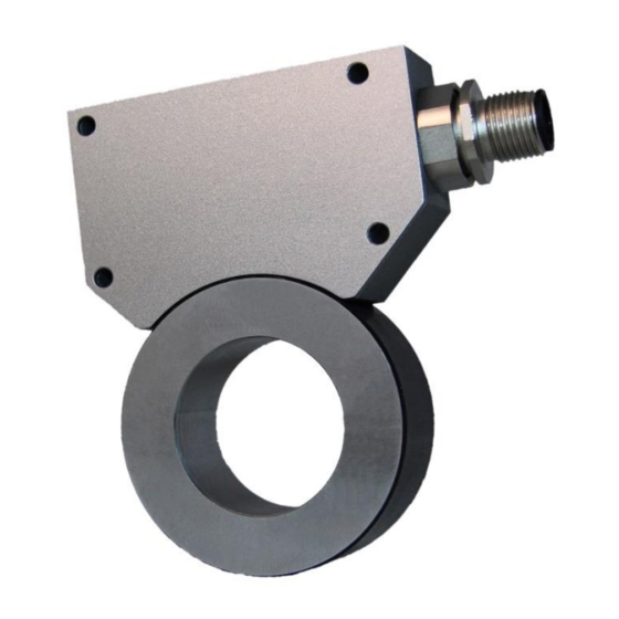
Product Features 3 Product Features The angle measuring system EMAX-RO is a combination of a sensor and a mag- netic ring. The magnetic ring is mounted directly to an engine shaft or an axle (see mounting suggestions 5.3). This ensures a quick and easy installation. EMAX-RO is especially suited for measuring rotative angles. -
Page 8: Technical Data
Technical Data 4 Technical Data Identification The type label serves for the identification of the unit. It is located on the housing of the sensor and gives the exact type designation (=order reference, see chapter type designation with the corresponding part number. Furthermore, the type label contains a unique, traceable device number. -
Page 9: Dimensions Of Magnetic Ring
Technical Data Dimensions of Magnetic Ring 4.3.1 Dimensions of Magnetic Ring without Protection Ring Ø 30 20.00 Ø 50.95 20.60 Required shaft / tolerance: Ø 30 Figure 3: Magnetic ring dimensions (without protection ring) Usage up to maximum 1000 rpm 4.3.2 Dimensions of Magnetic Ring with Protection Ring Ø... -
Page 10: Technical Data Sensor
Technical Data Technical Data Sensor EMAX-RO (standard version) Mechanical Data Measuring principle Absolute Repeat accuracy +/- 1 Increment System accuracy in µm at 20 °C +/- (150 + 20 x L) / + / - 0.35° (type designation 010) +/- (50 + 20 x L) / + / - 0.16° (type designation F10) L = length in meter Sensor distance to magnetic ring max.1.0 mm without protection ring, max.0.45 mm with protection ring... -
Page 11: Installation And First Start-Up
Installation and First Start-Up 5 Installation and First Start-Up CAUTION Please read the operating manual carefully before using the device! Strictly observe the In- stallation instructions! In case of damage caused by failure to observe this operating manual, the warranty expires. ELGO is not liable for any secondary damage and for damage to persons, property or as- sets. -
Page 12: Installing Of The Sensor Head
Installation and First Start-Up Installing of the Sensor Head 5.2.1 Installing Tolerances Note! Distance between magnetic ring and active sensor area of the measuring system is between 0.50 mm and 1.00 mm without protection ring, and max. 0.45 mm with protection ring. Observe the given tolerances when installing the system! Outside this area, proper function- ing of the device cannot be guaranteed! Install sensor with M3 screws, see Chapter “Dimensions of Sensor and Magnetic ring”... - Page 13 Installation and First Start-Up Distance detection via EMAX-RO Sensor Direction arrow for assembly Absolute track Fine interpolation track Symbolic illustration Figure 6: Mounting direction of EMAX-RO Sensor to Magnetic Ring 5.2.3 Offset After the installation of the magnetic tape and the measuring system (EMAX-RO) a value is transmitted by the interface.
-
Page 14: Magnetic Ring Mounting Suggestions
Installation and First Start-Up Magnetic Ring mounting suggestions The magnetic ring may be mounted in various ways on a shaft. The examples will below show non-binding pro- posals how the magnetic ring can be installed. 5.3.1 Example for adhesive mounting: Loctite 648 adhesive Steel shaft with h6 fit EMAX RO magnetic ring... -
Page 15: Interfaces And Assignment
Interfaces and Assignment 6 Interfaces and Assignment Pin Assignment Table 2 Pin Assignment SSI / optionally with incremental signals The colours are valid with the DKA signal cable which is available as accessories. Cable Plug 12 pol M12x1 PIN-Nr. Function 1 (white) 0 V/GND 2 (brown) -
Page 16: Interfaces
Interfaces and Assignment Interfaces The following chapters give detailed information about the connections and interfaces. 6.2.1 Interface SSI (option SB0 and SG0) If the clock is not interrupted for the time Tm-T/2 (output of further 25 periods), the shift register clocks once again the same data value (error recognition in evaluation). - Page 17 Interfaces and Assignment 6.2.3 Incremental Signal TTL / HTL As an option, there are two 90 ° phase shifted rectangle signals (compatible to rotary encoders) with HTL or TTL output level (push-pull, push / pull). HTL (10 … 30 V) TTL (5 V) 0 VDC 90°...
-
Page 18: Disturbances, Maintenance, Cleaning
Disturbances, Maintenance, Cleaning 7 Disturbances, Maintenance, Cleaning This chapter describes possible causes for disturbances and measures for their removal. In case of increased disturbances, please follow the measures for fault clearance in chapter 7.1. In case of disturbances that cannot be eliminated by following the advice and the fault clearance measures given here, please contact the manufacturer (see second page). -
Page 19: Maintenance
Disturbances, Maintenance, Cleaning 7.3 Maintenance The device is maintenance-free. WARNING! Danger through non-conventional maintenance! Non-conventional maintenance can lead to severe injuries and damage of property. Therefore: Maintenance works may only be completed by staff that has been authorized and trained by the operator. 7.4 Cleaning WARNING! The device can only be cleaned with a damp cloth, do not use aggressive cleanser! -
Page 20: Type Designation
Type Designation 8 Type Designation Type Designation EMAX-RO RMAX XXXX XXXX XXXX EEEE GGGG JJJJ Series/Type: RMAX = EMAX RO measuring system SN-number: 00 = standrad Signal cable length: 000 = without cable (standard) Resolution: 010 =10 µm Interface: SB0 = SSI Interface (25 Bit Binary code) SG0 = SSI Interface (25 Bit Gray code) CA0 = CANopen (DS 406) CN0 = CAN BASIC ELGO (on request) -
Page 21: Accessories
Type Designation Accessories Table 4 Accessories Order Designation Description MR 00 051 030 206 0032 050 2 14021 Magnetic ring without protection ring (max. 1000 rpm) MR 00 052 030 206 0032 050 2 14021 Magnetic ring with protection ring (max. 20000 rpm) DKA-00-RCF0-050-XXXX-12-T-D-S EMAX-RO connection cable with (female)12-pin M12 connector, 05.0 = cable length 5.0 m, customer sided with an open cable... - Page 22 Type Designation Notes: - 22 -...
-
Page 23: Index
Index 9 Index Accessories ............. 21 Mounting direction .......... 12 Accident prevention regulations......4 Offset ............. 13 Causes of risk ............ 5 Operating area ..........11 Cleaning ........... 18, 19 Operational safety ..........4 Conventional use ..........6 Order reference ..........8 Demounting ............ - Page 24 Document- No.: 799000708 / Rev. 3 ELGO Electronic GmbH & Co. KG Measuring | Positioning | Control Document- Name: EMAX-RO-00-MA-E_46-17 Carl - Benz - Str. 1, D-78239 Rielasingen Subject to change - © 2017 Fon:+49 (0) 7731 9339-0, Fax:+49 (0) 7731 28803 ELGO Electronic GmbH &...
Need help?
Do you have a question about the EMAX-RO Series and is the answer not in the manual?
Questions and answers