Advertisement
Quick Links
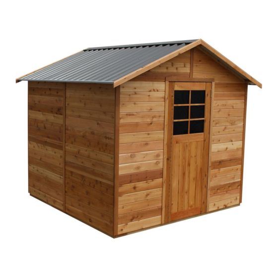
STILLA
ASSEMBLY INSTRUCTIONS
'Glendale' 8x8
S3031
Every part needed to construct your shed is included inside the pack; cedar
panels, doors, windows, hardware kits & roof sheeting. Please ensure you fully
unpack all the parts & check against the parts checklist before contacting
customer service about anything you believe may be missing. Thank-you!
Advertisement

Related Manuals for STILLA Glendale


Summary of Contents for STILLA Glendale
- Page 1 STILLA ASSEMBLY INSTRUCTIONS ‘Glendale’ 8x8 S3031 Every part needed to construct your shed is included inside the pack; cedar panels, doors, windows, hardware kits & roof sheeting. Please ensure you fully unpack all the parts & check against the parts checklist before contacting...
- Page 2 • If you are installing your shed on the Stilla heavy duty floor, this can be placed on unlevelled surfaces and levelled up by using the 100x100 stumps provided.
- Page 3 GLENDALE 8x8 PARTS CHECKLIST Part Code Checked Part Description Cedar Clad Panel 1200x1890mm Cedar Clad Panel 780x1890mm(480x1890mm if Double Doors) 8ft Gable Rafters 1230x42x35mm Colonial Door 830x1875mm (714x1875mm if double doors) 2710mm Channel TB/BB Top Batten/Bottom Batten 2710mm 1480mm Roof Sheeting...
- Page 4 Double Doors – Option – Changes to above kit Part Code Part Description Colonial Door 714x1875mm Cedar Clad Panel 480x1890mm Double Door Head 1440x42x35mm Double Door Stop 1440x42x18mm Door Leaver Packer 100x100x18mm 8x8 Lean To – Option – Add Extra Screws Part Code Part Description Beam 2710x70x35mm...
- Page 5 If no floor option was purchased, go to step 2.0 (Wall Assembly) STEP 1.0 FLOOR KIT 1.0 – FLOOR KIT PART CODE QTY DESCRIPTION End Plate 2470mm Single Joist 2330mm Double Joist 2330mm (42x35mm part of DJ goes at the top inside) Floor Nog 100BS 100mm Batten screw (Heavy Duty Floor Only)
- Page 6 HEAVY DUTY FLOOR KIT Heavy duty floor can be installed on unlevelled ground – use supplied logs to level your floor by digging them into the ground. Install heavy duty floor kit using (L) 4 logs – 1 in each corner (position shown above) screw through frame into log using 4 x 100BS per corner Ensure floor frame is square by measuring from corner to corner diagonally prior to installing flooring.
- Page 7 STEP 2.0 WALL ASSEMBLY 2.0 - ASSEMBLY PARTS – WALL ASSEMBLY PART CODE QTY DESCRIPTION Front Wall panel 1200mm Wall panel 65HHS 65mm Hex head screw -If optional window was purchased, it can take the place of any 1200mm (P) panel. 2.0 - ASSEMBLY –...
- Page 8 STEP 2.1 WALL ASSEMBLY 2.1 - ASSEMBLY PARTS – WALL ASSEMBLY PART CODE QTY DESCRIPTION 1200mm Wall panel 65HHS 65mm Hex head screw 2.1 - ASSEMBLY – WALL ASSEMBLY Screw through P into P (Top, centre & bottom) using 3 x 65HHS, holding studs flush on the inside.
- Page 9 STEP 2.2 WALL ASSEMBLY 2.2 - ASSEMBLY PARTS – WALL ASSEMBLY PART CODE QTY DESCRIPTION 1200mm Wall panel 65HHS 65mm Hex head screw 2.2 - ASSEMBLY – WALL ASSEMBLY Screw through P into P (Top, centre & bottom) using 3 x 65HHS, holding studs flush on the outside.
- Page 10 STEP 2.3 WALL ASSEMBLY 2.3 - ASSEMBLY PARTS – WALL ASSEMBLY PART CODE QTY DESCRIPTION 1200mm Wall panel 65HHS 65mm Hex head screw 2.3 - ASSEMBLY – WALL ASSEMBLY Screw through P into P (Top, centre & bottom) using 3 x 65HHS, holding studs flush on the inside.
- Page 11 STEP 2.4 WALL ASSEMBLY 2.4 - ASSEMBLY PARTS – WALL ASSEMBLY PART CODE QTY DESCRIPTION 1200mm Wall panel 65HHS 65mm Hex head screw 2.4 - ASSEMBLY – WALL ASSEMBLY Screw through P into P (top, centre & bottom) using 3 x 65HHS holding studs flush on the outside.
- Page 12 STEP 2.5 WALL ASSEMBLY 2.5 - ASSEMBLY PARTS – WALL ASSEMBLY PART CODE QTY DESCRIPTION 1200mm Wall panel 65HHS 65mm Hex head screw 2.5 - ASSEMBLY – WALL ASSEMBLY Screw through P into P (top, centre & bottom) using 3 x 65HHS holding studs flush on the inside.
- Page 13 STEP 2.6 WALL ASSEMBLY 2.6 - ASSEMBLY PARTS – WALL ASSEMBLY PART CODE QTY DESCRIPTION Front Wall panel 65HHS 65mm Hex head screw 2.6 - ASSEMBLY – WALL ASSEMBLY Screw through FP into P (top, centre & bottom) using 3 x 65HHS holding studs flush on the outside.
- Page 14 2 x 65HHS in centre stud. (Image 1) Turn one gable over. Position (SCS) Stilla branded cover strip flush with bottom cedar board and flush on each end. Nail through cover strip into gable using 40N. (Image 2) Position (FGS) front gable cover strip over join in front gable.
- Page 15 Carefully position front gable in position ensuring tongue on wall goes into groove on gable. Fasten up through front panels using 2 x 65HHS either side. Repeat with back gable using 1 x 65HHS either side and centre. Front gable has door head and Stilla strip. 14 | P a g e...
- Page 16 STEP 3.0 ROOF ASSEMBLY 3.0 - ASSEMBLY PARTS – ROOF ASSEMBLY PART CODE QTY DESCRIPTION Bottom batten Top batten Rafter 100BS 100mm Batten screw 3.0 - ASSEMBLY – ROOF ASSEMBLY Push R into BB and TB and insert 100BS into predrilled hole to fasten. 1 x 100BS per join. 15 | P a g e...
- Page 17 STEP 3.1 ROOF ASSEMBLY 3.1 - ASSEMBLY PARTS – ROOF ASSEMBLY PART CODE QTY DESCRIPTION 1480mm sheet 40RS 40mm Roof screw 25RS 25mm Roof screw 3.1 - ASSEMBLY – ROOF ASSEMBLY Lay roof frame on a hard surface. Position roof sheet’s (RS) flush at top and flush with end of roof battens.
- Page 18 STEP 3.2 ROOF ASSEMBLY 3.2 - ASSEMBLY PARTS – ROOF ASSEMBLY PART CODE QTY DESCRIPTION 1480mm roof sheet 40RS 40mm Roof screw 25RS 25mm Roof Screw 3.2 - ASSEMBLY – ROOF ASSEMBLY Complete laying roof sheeting out on frame. Fasten roof sheets to battens in sequence shown.
- Page 19 STEP 3.3 ROOF ASSEMBLY 3.3 - ASSEMBLY PARTS – ROOF ASSEMBLY PART CODE QTY DESCRIPTION 40RS 40mm Roof screw 25RS 25mm Roof screw 3.3 - ASSEMBLY – ROOF ASSEMBLY Complete screwing roof off at top. 1 x 25RS in pan beside every rib. Once top complete screw bottom off using 1 x 40RS in every rib.
- Page 20 STEP 3.4 CHANNEL ASSEMBLY If you purchased the Lean-To/Annex, leave the channel off the side you will be installing your Lean-To/Annex 3.4 - ASSEMBLY PARTS – CHANNEL ASSEMBLY PART CODE QTY DESCRIPTION 12mm self tapping screw 2.71m Channel 3.4 - ASSEMBLY – CHANNEL ASSEMBLY Fasten capping C to roof using 5 x ST.
- Page 21 STEP 3.5 ROOF INSTALLATION 3.5 - ASSEMBLY PARTS – ROOF INSTALLATION PART CODE QTY DESCRIPTION Completed roof panels 65HHS 65mm Hex head screw 3.5 - ASSEMBLY – ROOF INSTALLATION Slide roof panel into position and fasten up through front and back gables. Ensure roof rafters are flush with gables.
- Page 22 If Double door option was chosen go to step 4.1 STEP 3.7 DOOR HINGE ASSEMBLY 3.7 - ASSEMBLY PARTS –DOOR HINGE ASSEMBLY PART CODE DESCRIPTION Hinge Hinge Screw Door 3.7 - ASSEMBLY –DOOR HINGE ASSEMBLY Place door on back and hold hinge (H) in position. Fasten hinges to door using 3 x hinge screws (HS) per hinge.
- Page 23 STEP 3.8 DOOR INSTALLATION 3.8 - ASSEMBLY PARTS –DOOR INSTALLATION PART CODE DESCRIPTION Door Hinge screw 3.8 - ASSEMBLY –DOOR INSTALLATION Hold door in position, 3mm down from top. Front of the door when closed will be flush with front of VJ cladding. Screw through hinge into front wall (as pictured).
- Page 24 STEP 3.9 DOOR HANDLE ASSEMBLY 3.9 - ASSEMBLY PARTS – DOOR HANDLE ASSEMBLY PART CODE QTY DESCRIPTION T Handle 3.9 - ASSEMBLY - DOOR HANDLE ASSEMBLY Remove bolts and leaver from back of T Handle (TH). Mark and drill 12mm centre hole in position shown, 50mm in from door edge.
- Page 25 If Double door option was not chosen please go to step 4.7 STEP 4.1 DOUBLE DOOR HINGE ASSEMBLY 4.1 - ASSEMBLY PARTS – DOUBLE DOOR HINGE ASSEMBLY PART CODE DESCRIPTION Hinge Hinge Screw Doors 4.1 - ASSEMBLY – DOUBLE DOOR HINGE ASSEMBLY Place door on back and hold hinge (H) in position.
- Page 26 STEP 4.2 DOUBLE DOOR INSTALLATION 4.2 - ASSEMBLY PARTS – DOUBLE DOOR INSTALLATION PART CODE DESCRIPTION Doors Hinge screw 4.2 - ASSEMBLY – DOUBLE DOOR INSTALLATION Hold door in position, 3mm down from top. Front of the door when closed will be flush with front of VJ cladding.
- Page 27 STEP 4.3 PAD BOLT INSALLATION 4.3 - ASSEMBLY PARTS – PAD BOLT INSTALLATION PART CODE DESCRIPTION Pad bolt Hinge Screw 4.3 - ASSEMBLY – PAD BOLT INSTALLATION Hold PB in position and fasten to door. Mark centre of bolt and drill 12mm hole in marked closed position.
- Page 28 STEP 4.5 DOOR HANDLE ASSEMBLY 4.5 - ASSEMBLY PARTS – DOOR HANDLE ASSEMBLY PART CODE QTY DESCRIPTION T Handle Leaver Packer Hinge screw 4.5 - ASSEMBLY – DOOR HANDLE ASSEMBLY Holding P in position, fasten to door (door with pad bolts) Holding door in closed position, flush with other door - slide leaver onto T Handle and tighten once hitting packer on fixed door.
- Page 29 STEP 4.6 DOOR STOP ASSEMBLY 4.6 - ASSEMBLY PARTS – DOOR STOP ASSEMBLY PART CODE QTY DESCRIPTION Door Stop 40mm nail 4.6 - ASSEMBLY – DOOR STOP Place door stop in position at base of door between front FP’s. Nail door stop down using 2 x 40n.
- Page 30 STEP 4.8 CORNER POST ASSEMBLY Before nailing each corner posts on we recommend running a bead of silicone down these two lines as per images below. 4.8 - ASSEMBLY PARTS – CORNER POST ASSEMBLY PART CODE QTY DESCRIPTION 1910mm Corner post’s 40mm Nail 4.8 - ASSEMBLY –...
- Page 31 STEP 4.9 COVER STRIP ASSEMBLY Before nailing cover strips on we recommend running a bead of silicone down this join as per images below. 4.9 - ASSEMBLY PARTS – COVER STRIP ASSEMBLY PART CODE QTY DESCRIPTION 1890mm Cover strip 40mm Nail 4.9 - ASSEMBLY –...
- Page 32 STEP 5.0 FASCIA ASSEMBLY 5.0 - ASSEMBLY PARTS – FASCIA ASSEMBLY PART CODE QTY DESCRIPTION Fascia 40mm Nail 5.0 - ASSEMBLY – FASCIA ASSEMBLY Hold fascia’s in position. Flush with bottom of battens and meeting evenly at the top. Nail into end of Battens.
- Page 33 STEP 5.1 RIDGE CAP INSTALLATION 5.1 - ASSEMBLY PARTS – RIDGE CAP INSTALLATION PART CODE QTY DESCRIPTION 1520mm Ridge Cap 40RS 40mm Roof screw 5.1 - ASSEMBLY – RIDGE CAP INSTALLATION Slide ridge caps into position. Make sure peak of ridge cap is in line with peak of fascia’s. Screw through ridge cap into 2 rib in from end and through into batten.
- Page 34 STEP 6.0 LEAN TO / ANNEX If you did not purchase this option please skip this step 6.0 - ASSEMBLY PARTS – LEAN TO / ANNEX PART CODE QTY DESCRIPTION Verandah beam Batten Verandah rafter 75mm Nail 6.0 - ASSEMBLY – LEAN TO / ANNEX Nail through B &...
- Page 35 STEP 6.1 LEAN TO / ANNEX 6.1 - ASSEMBLY PARTS – LEAN TO / ANNEX PART CODE QTY DESCRIPTION Verandah roof sheeting 40RS 40mm roof screw 25RS 25mm roof screw 6.1 - ASSEMBLY – LEAN TO / ANNEX Screw roof sheeting to frame using 2 x 25RS at top and 2 x 40RS at bottom. Note that the top screws go into the pan of the roof sheet and the bottom screws go into the rib of the roof sheet.
- Page 36 STEP 6.2 LEAN TO / ANNEX 6.2 - ASSEMBLY PARTS – LEAN TO / ANNEX PART CODE QTY DESCRIPTION Verandah roof sheeting 40RS 40mm roof screw 25RS 25mm roof screw 6.2 - ASSEMBLY – LEAN TO / ANNEX Place the remaining 3 roof sheets in position and finish screwing off the top and bottom using 25RS in every pan at the top and 40RS in every rib at the bottom.
- Page 37 STEP 6.3 LEAN TO / ANNEX 0.0 - ASSEMBLY PARTS – LEAN TO / ANNEX PART CODE QTY DESCRIPTION Verandah posts 100BS 100mm batten screw 65HHS 65mm hex head screw 0.0 - ASSEMBLY – LEAN TO / ANNEX Using 3 people, butt the verandah roof hard up under shed roof as shown in picture. Support front of verandah roof while fastening through frame into shed wall studs using 4 x 100BS.
- Page 38 STEP 6.4 LEAN TO / ANNEX 6.4 - ASSEMBLY PARTS – LEAN TO / ANNEX PART CODE QTY DESCRIPTION Verandah fascia 40mm nail 6.4 - ASSEMBLY – LEAN TO / ANNEX Once fascia’s are on shed, trim lean-to/annex fascia to butt in and finish correctly. Nail through fascia using 4 x 40N per fascia.
-
Page 39: Product Maintenance
TO REGISTER YOUR WARRANTY Thank-you for purchasing a STILLA product. To register your 10 year product warranty, please go to www.stilla.com.au/warranty and complete the online form. We recommend that you complete this step once you have finished installing your product. - Page 40 SHOW US YOUR SHED We would love to see a photo of your STILLA product installed in your backyard. Please upload this image when completing the warranty registration. Alternatively, you can send the photos by email to sales@stilla.com.au. If you require any assistance, please feel free to call or email.
Need help?
Do you have a question about the Glendale and is the answer not in the manual?
Questions and answers