Advertisement
Quick Links
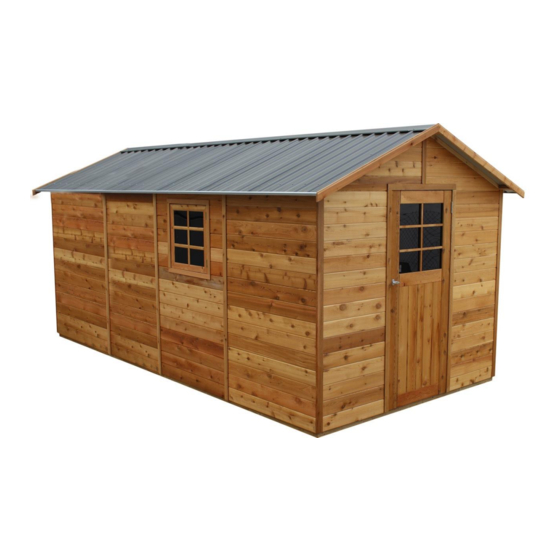
STILLA
ASSEMBLY INSTRUCTIONS
'Chatswood' 8x16
S3071
Every part needed to construct your shed is included inside the pack; cedar
panels, doors, windows, hardware kits & roof sheeting. Please ensure you fully
unpack all the parts & check against the parts checklist before contacting
customer service about anything you believe may be missing. Thank-you!
Advertisement

Subscribe to Our Youtube Channel
Related Manuals for STILLA Chatswood


Summary of Contents for STILLA Chatswood
- Page 1 STILLA ASSEMBLY INSTRUCTIONS ‘Chatswood’ 8x16 S3071 Every part needed to construct your shed is included inside the pack; cedar panels, doors, windows, hardware kits & roof sheeting. Please ensure you fully unpack all the parts & check against the parts checklist before contacting...
- Page 2 Caution Please be careful when handling all components, some parts have sharp metal edges. Always wear work gloves, eye protection and long sleeves when assembling or maintaining your shed. Tools required for assembly • Level • Phillips head drive • Drill •...
- Page 3 CHATSWOOD 8x16 PARTS CHECKLIST Part Code Checked Part Description Cedar Clad Panel 1200x1890mm Cedar Clad Window Panel 1200x1890mm Cedar Clad Panel 780x1890mm (480x1890 if Double Doors) 8ft Gable Rafter 1230x42x35mm Colonial Door 830x1875mm (714X1875 if double doors) 2710mm Channel TB/BB...
- Page 4 Double Doors – Option Part Code Checked Part Description Colonial Door 714x1875mm Cedar Clad Panel 480x1890mm Door Leaver Packer 100x100x18mm Door stop 1440x42x19mm Door head 1440x42x35mm 8x16 Lean To – Option – Add Extra Screws Part Code Checked Part Description Beam 5105x70x35mm Verandah Beam 5105x140x35mm Verandah Rafter 1000x42x35mm...
- Page 5 If no floor option was purchased, go to step 2.0 (Wall Assembly) STEP 1.0 FLOOR KIT 1.0 – FLOOR KIT PART CODE QTY DESCRIPTION End Plate 2470mm Single Joist 2330mm Double Joist 2330mm (42x35mm part of DJ goes at the top inside) Floor Nog 100BS 100mm Batten screw (Heavy Duty Floor Only)
- Page 6 Ensure floor frame is square by measuring from corner to corner diagonally prior to installing flooring. STEP 1.1 FLOORING INSTALLATION 1.1 – FLOOR INSTALLATION PART CODE DESCRIPTION Floor Board 1797x800mm Floor Board 597x800mm Floor Board 1797x711mm Floor Board 597x711mm 50PS 50mm Philips Screw 1.1 –...
- Page 7 STEP 2.0 WALL ASSEMBLY- WALL PANEL (WP) (1200MM WINDOW PANEL) CAN BE POSITIONED ANYWHERE ON THE SHED WHERE WE HAVE USED A (P) (1200MM WALL PANEL). 2.0 - ASSEMBLY PARTS – WALL ASSEMBLY PART CODE QTY DESCRIPTION Front wall panel 1200mm Wall panel 65HHS 65mm Hex head screw...
- Page 8 STEP 2.1 WALL ASSEMBLY 2.1 - ASSEMBLY PARTS – WALL ASSEMBLY PART CODE QTY DESCRIPTION 1200mm Wall panel 65HHS 65mm Hex head screw 2.1 - ASSEMBLY PARTS – WALL ASSEMBLY Screw through P into P (Top, centre & bottom) using 3 x 65HHS, holding studs flush on the inside.
- Page 9 STEP 2.2 WALL ASSEMBLY 2.2 - ASSEMBLY PARTS – WALL ASSEMBLY PART CODE QTY DESCRIPTION 1200mm Wall panel 65HHS 65mm Hex head screw 2.2 - ASSEMBLY PARTS – WALL ASSEMBLY Screw through P into P (Top, centre & bottom) using 3 x 65HHS, holding studs flush on the inside.
- Page 10 STEP 2.3 WALL ASSEMBLY 2.3 - ASSEMBLY PARTS – WALL ASSEMBLY PART CODE QTY DESCRIPTION 1200mm Wall panel 65HHS 65mm Hex head screw 2.3 - ASSEMBLY PARTS – WALL ASSEMBLY Screw through P into P (Top, centre & bottom) using 3 x 65HHS, holding studs flush on the inside.
- Page 11 STEP 2.4 WALL ASSEMBLY 2.4 - ASSEMBLY PARTS – WALL ASSEMBLY PART CODE QTY DESCRIPTION 1200mm Wall panel 65HHS 65mm Hex head screw 2.4 - ASSEMBLY PARTS – WALL ASSEMBLY Screw through P into P (top, centre & bottom) using 3 x 65HHS holding studs flush on the outside.
- Page 12 STEP 2.5 WALL ASSEMBLY 2.5 - ASSEMBLY PARTS – WALL ASSEMBLY PART CODE QTY DESCRIPTION 1200mm Wall panel 65HHS 65mm Hex head screw 2.5 - ASSEMBLY PARTS – WALL ASSEMBLY Screw through P into P (top, centre & bottom) using 3 x 65HHS holding studs flush on the inside.
- Page 13 STEP 2.6 WALL ASSEMBLY 2.6 - ASSEMBLY PARTS – WALL ASSEMBLY PART CODE QTY DESCRIPTION 1200mm Wall panel 65HHS 65mm Hex head screw 2.6 - ASSEMBLY PARTS – WALL ASSEMBLY Screw through P into P (top, centre & bottom) using 3 x 65HHS holding studs flush on the outside.
- Page 14 STEP 2.7 WALL ASSEMBLY 2.7 - ASSEMBLY PARTS – WALL ASSEMBLY PART CODE QTY DESCRIPTION 1200mm Wall panel 65HHS 65mm Hex head screw 2.7 - ASSEMBLY PARTS – WALL ASSEMBLY Screw through P into P (top, centre & bottom) using 3 x 65HHS holding studs flush on the inside.
- Page 15 STEP 2.8 WALL ASSEMBLY THE WINDOW PANEL (WP – 1200MM WINDOW PANEL) CAN BE POSITIONED ANYWHERE ON THE SHED WHERE WE HAVE USED A P (1200MM WALL PANEL) 2.8 - ASSEMBLY PARTS – WALL ASSEMBLY PART CODE QTY DESCRIPTION 1200mm Window wall panel 65HHS 65mm Hex head screw 2.8 - ASSEMBLY –...
- Page 16 STEP 2.9 WALL ASSEMBLY 2.9 - ASSEMBLY PARTS – WALL ASSEMBLY PART CODE QTY DESCRIPTION 1200mm Wall panel 65HHS 65mm Hex head screw 2.9 - ASSEMBLY PARTS – WALL ASSEMBLY Screw through WP into P (top, centre & bottom) using 3 x 65HHS holding studs flush on the inside.
- Page 17 STEP 3.0 WALL ASSEMBLY 3.0 - ASSEMBLY PARTS – WALL ASSEMBLY PART CODE QTY DESCRIPTION Front wall panel 65HHS 65mm Hex head screw 3.0 - ASSEMBLY PARTS – WALL ASSEMBLY Screw through WP into P (top, centre & bottom) using 3 x 65HHS holding studs flush on the outside.
- Page 18 Screw together in position shown, holding flush at the bottom (using 2 x 65HHS). Repeat for other gable. Turn one complete gable over (cedar facing upwards). Position (SCS) Stilla branded cover strip flush with bottom of gable Board and flush on each end. Nail through cover strip into gable using 40N.
- Page 19 STEP 3.2 FRONT GABLE ASSEMBLY 3.2 - ASSEMBLY PARTS – GABLE ASSEMBLY PART CODE QTY DESCRIPTION Assembled front gable Assembled back gable 65HHS 65mm Hex head screw 3.2 - ASSEMBLY – GABLE ASSEMBLY Carefully position front gable in position ensuring tongue on wall goes into groove on gable. Fasten up through front panels using 2 x 65HHS either side.
- Page 20 STEP 3.3 RIDGE BEAM BRACKET 3.3 - ASSEMBLY PARTS – RIDGE BEAM BRACKET PART CODE QTY DESCRIPTION Ridge beam bracket 50PS 50mm screws 3.3 - ASSEMBLY – RIDGE BEAM BRACKET Measure down from Gable peak 145mm and mark with pen/pencil. Hold ridge beam bracket (RBB) below mark (top of bracket flush with mark) and screw through bracket into gable using 2 x 50PS per bracket.
- Page 21 STEP 3.4 RIDGE BEAM 3.4 - ASSEMBLY PARTS – RIDGE BEAM PART CODE QTY DESCRIPTION Ridge beam 50PS 50mm screws. 3.4 - ASSEMBLY – RIDGE BEAM Place ridge beam on top of ridge beam brackets, ensure beam is hard up against gable. Screw up through ridge beam bracket into ridge beam using 2 x 50PS each end.
- Page 22 STEP 3.5 ROOF ASSEMBLY 3.5 - ASSEMBLY PARTS – ROOF ASSEMBLY PART CODE QTY DESCRIPTION Bottom batten Top batten Rafter 100BS 100mm Batten screw 3.5 - ASSEMBLY – ROOF ASSEMBLY Push R into BB and TB and insert 100BS into predrilled hole to fasten. 1 x 100BS per join. 21 | P a g e...
- Page 23 STEP 3.6 ROOF ASSEMBLY 3.6 - ASSEMBLY PARTS – ROOF ASSEMBLY PART CODE QTY DESCRIPTION 1480mm roof sheet 40RS 40mm Roof screw 25RS 25mm Roof screw 3.6 - ASSEMBLY – ROOF ASSEMBLY Lay roof frame on a hard surface. Position 1 roof sheet (RS) at each end, flush at top and flush with end of roof battens.
- Page 24 STEP 3.7 ROOF ASSEMBLY 3.7 - ASSEMBLY PARTS – ROOF ASSEMBLY PART CODE QTY DESCRIPTION 1480mm roof sheet 40RS 40mm Roof screw 25RS 25mm Roof screw 3.7 - ASSEMBLY – ROOF ASSEMBLY Complete laying roof sheeting out on frame. Fasten roof sheets to battens in sequence shown.
- Page 25 STEP 3.8 ROOF ASSEMBLY 3.8 - ASSEMBLY PARTS – ROOF ASSEMBLY PART CODE QTY DESCRIPTION 40RS 40mm Roof screw 25RS 25mm Roof screw 3.8 - ASSEMBLY – ROOF ASSEMBLY Complete screwing roof off at top. 1 x 25RS in pan beside every rib. Once top complete screw bottom off using 1 x 40RS through every rib.
- Page 26 STEP 3.9 CHANNEL ASSEMBLY If you purchased the Lean-To/Annex, leave the channel off the side you will be installing your Lean-To/Annex 3.9 - ASSEMBLY PARTS – CHANNEL ASSEMBLY PART CODE QTY DESCRIPTION 12mm self-tapping screw Channel 3.9 - ASSEMBLY – CHANNEL ASSEMBLY Slide 2115mm channel onto end of roof sheeting over hang.
- Page 27 STEP 4.0 ROOF INSTALLATION 4.0 - ASSEMBLY PARTS – ROOF INSTALLATION PART CODE QTY DESCRIPTION Completed roof panels 65HHS 65mm Hex head screw 4.0 - ASSEMBLY – ROOF INSTALLATION Slide roof panel into position and fasten up through front and back gables. Ensure roof rafters are flush with gables.
- Page 28 STEP 4.1 COLLAR TIE INSTALLATION 4.1 - ASSEMBLY – COLLAR TIE INSTALLATION PART CODE QTY DESCRIPTION Collar tie 65HHS 65mm Hex head screw 4.1 - ASSEMBLY PARTS – COLLAR TIE INSTALLATION Holding Collar tie tight and level in position screw through CT into Roof Rafters. Screw through center on angle up into ridge beam.
- Page 29 If Double door option was chosen please go to step 4.6 STEP 4.2 DOOR HINGE ASSEMBLY 4.2 - ASSEMBLY PARTS –DOOR HINGE ASSEMBLY PART CODE DESCRIPTION Hinge Hinge Screw Door 4.2 - ASSEMBLY –DOOR HINGE ASSEMBLY Place door on back and hold hinge (H) in position. Fasten hinges to door using 3 x hinge screws (HS) per hinge.
- Page 30 STEP 4.3 DOOR INSTALLATION 4.3 - ASSEMBLY PARTS –DOOR INSTALLATION PART CODE DESCRIPTION Door Hinge screw 4.3 - ASSEMBLY –DOOR INSTALLATION Hold door in position, 3mm down from top. Front of the door when closed will be flush with front of VJ cladding. Screw through hinge into front wall (as pictured).
- Page 31 STEP 4.4 DOOR HANDLE ASSEMBLY 4.4 - ASSEMBLY PARTS – DOOR HANDLE ASSEMBLY PART CODE QTY DESCRIPTION T Handle 4.4 - ASSEMBLY – DOOR HANDLE ASSEMBLY Remove bolts and leaver from back of T Handle (TH). Mark and drill 12mm centre hole in position shown, 50mm in from door edge.
- Page 32 If Double door option was not chosen please go to step 5.1 STEP 4.6 DOUBLE DOOR HINGE ASSEMBLY 4.6 - ASSEMBLY PARTS – DOUBLE DOOR HINGE ASSEMBLY PART CODE DESCRIPTION Hinge Hinge Screw Doors 4.6 - ASSEMBLY – DOUBLE DOOR HINGE ASSEMBLY Place door on back and hold hinge (H) in position.
- Page 33 STEP 4.7 DOUBLE DOOR INSTALLATION 4.7 - ASSEMBLY PARTS – DOUBLE DOOR INSTALLATION PART CODE DESCRIPTION Doors Hinge screw 4.7 - ASSEMBLY – DOUBLE DOOR INSTALLATION Hold door in position, 3mm down from top. Front of the door when closed will be flush with front of VJ cladding.
- Page 34 STEP 4.8 PAD BOLT INSALLATION 4.8 - ASSEMBLY PARTS – PAD BOLT INSTALLATION PART CODE DESCRIPTION Pad bolt Hinge Screw 4.8 - ASSEMBLY – PAD BOLT INSTALLATION Hold PB in position and fasten to door. Mark centre of bolt and drill 12mm hole in marked closed position.
- Page 35 STEP 5.0 DOOR HANDLE ASSEMBLY 5.0 - ASSEMBLY PARTS – DOOR HANDLE ASSEMBLY PART CODE QTY DESCRIPTION T Handle Leaver Packer Hinge screw 5.0 - ASSEMBLY – DOOR HANDLE ASSEMBLY Holding P in position, fasten to door (door with pad bolts) Holding door in closed position, flush with other door - slide leaver onto T Handle and tighten once hitting packer on fixed door.
- Page 36 STEP 5.2 CORNER POST ASSEMBLY 5.2 - ASSEMBLY PARTS – CORNER POST ASSEMBLY PART CODE QTY DESCRIPTION 1890mm Corner post’s 40mm Nail 5.2 - ASSEMBLY – CORNER POST ASSEMBLY Hold corner post (CP) in position. Fasten through corner post into wall stud using 6 x 40mm nail.
- Page 37 STEP 5.3 COVER STRIP ASSEMBLY 5.3 - ASSEMBLY PARTS – COVER STRIP ASSEMBLY PART CODE QTY DESCRIPTION 1890mm Cover strip 40mm Nail 5.3 - ASSEMBLY – COVER STRIP ASSEMBLY Hold cover strips (CS) over join on wall panel. Nail through cover strip into wall panel using 6 x 40mm nails (40N) evenly spaced, per strip.
- Page 38 STEP 5.4 FASCIA ASSEMBLY 5.4 - ASSEMBLY PARTS – FASCIA ASSEMBLY PART CODE QTY DESCRIPTION Fascia 40mm Nail 5.4 - ASSEMBLY – FASCIA ASSEMBLY Hold fascia’s in position. Flush with bottom of battens and joining evenly at the top. STEP 5.5 RIDGE CAP INSTALLATION 5.5 - ASSEMBLY PARTS –...
- Page 39 STEP 5.6 8’ LOFT SHELF If you did not purchase this item, please skip this step. 5.6 - ASSEMBLY PARTS – 8’ LOFT SHELF PART CODE QTY DESCRIPTION 8’ Loft shelf 65HHS 65mm Hex head screw Shelf support 5.6 - ASSEMBLY – 8’ LOFT SHELF Holding loft shelf in position screw up through support plate into wall frame at each corner.
- Page 40 STEP 6.0 LEAN TO / ANNEX If you did not purchase this option please skip this step 6.0 - ASSEMBLY PARTS – LEAN TO / ANNEX PART CODE QTY DESCRIPTION Verandah beam Batten Verandah rafter 75mm Nail 6.0 - ASSEMBLY – LEAN TO / ANNEX Nail through B &...
- Page 41 STEP 6.1 LEAN TO / ANNEX 6.1 - ASSEMBLY PARTS – LEAN TO / ANNEX PART CODE QTY DESCRIPTION Verandah roof sheeting 40RS 40mm roof screw 25RS 25mm roof screw 6.1 - ASSEMBLY – LEAN TO / ANNEX Screw roof sheeting to frame using 2 x 25RS at top and 2 x 40RS at bottom. Note that the top screws go into the pan of the roof sheet and the bottom screws go into the rib of the roof sheet.
- Page 42 STEP 6.2 LEAN TO / ANNEX 6.2 - ASSEMBLY PARTS – LEAN TO / ANNEX PART CODE QTY DESCRIPTION Verandah roof sheeting 40RS 40mm roof screw 25RS 25mm roof screw 6.2 - ASSEMBLY – LEAN TO / ANNEX Place the remaining 3 roof sheets in position and finish screwing off the top and bottom using 25RS in every pan at the top and 40RS in every rib at the bottom.
- Page 43 STEP 6.3 LEAN TO / ANNEX 6.3 - ASSEMBLY PARTS – LEAN TO / ANNEX PART CODE QTY DESCRIPTION Verandah posts 100BS 100mm batten screw 65HHS 65mm hex head screw 6.3 - ASSEMBLY – LEAN TO / ANNEX Using 3 people, butt the verandah roof hard up under shed roof as shown in picture. Support front of verandah roof while fastening through frame into shed wall studs using 4 x 100BS.
- Page 44 STEP 6.4 LEAN TO / ANNEX 6.4 - ASSEMBLY PARTS – LEAN TO / ANNEX PART CODE QTY DESCRIPTION Verandah fascia 40mm nail 6.4 - ASSEMBLY – LEAN TO / ANNEX Once fascia’s are on shed, trim lean-to/annex fascia to butt in and finish correctly. Nail through fascia using 4 x 40N per fascia.
- Page 45 44 | P a g e...
- Page 46 45 | P a g e...
-
Page 47: Product Maintenance
TO REGISTER YOUR WARRANTY Thank-you for purchasing a STILLA product. To register your 10 year product warranty, please go to www.stilla.com.au/warranty and complete the online form. We recommend that you complete this step once you have finished installing your product. - Page 48 SHOW US YOUR SHED We would love to see a photo of your STILLA product installed in your backyard. Please upload this image when completing the warranty registration. Alternatively, you can send the photos by email to sales@stilla.com.au. If you require any assistance, please feel free to call or email.
Need help?
Do you have a question about the Chatswood and is the answer not in the manual?
Questions and answers