Table of Contents
Advertisement
Advertisement
Table of Contents

Related Manuals for Denso SP1-QUBi


Summary of Contents for Denso SP1-QUBi
- Page 1 RF Tag Handy Scanner SP1-QUBi User’s Manual...
-
Page 2: Table Of Contents
Contents Contents ................. ii Preface ................... i About This Manual ................. ii Customer Registration and Inquiries ............iii SAFETY PRECAUTIONS ..............iv Components Required ..............ix ® Bluetooth Wireless Communication Link ............x Proper Care of the Scanner ..............xi Chapter 1 Names and Functions .............. -
Page 3: Preface
Preface Thank you for using the DENSO WAVE RF Tag Handy Scanner. Please read this manual thoroughly prior to operation to ensure full use of the product’s functionality, and store safely in a convenient location for quick reference even after reading. -
Page 4: About This Manual
(3) The modification of DENSO WAVE’s products by parties other than DENSO WAVE. • If it is judged by DENSO WAVE that malfunction of the product is due to the product having been dropped or subjected to impact, repairs will be made at a reasonable charge even within the warranty period. -
Page 5: Customer Registration And Inquiries
Please note that these privileges may be subject to change without prior notice.. How to Register Access the URL below and follow the instructions provided. https://www.denso-wave.com/ Inquiries For inquires relating to products, please access our website https://www.denso-wave.com . Technical inquiries can be made at our exclusive website for registered users (QBdirect). -
Page 6: Safety Precautions
SAFETY PRECAUTIONS Be sure to observe all these safety precautions. Please READ through these instructions carefully. They will enable you to use the scanner correctly. Always keep this manual nearby for speedy reference. Safety precautions description in this document. Strict observance of these warnings and cautions is a MUST for preventing accidents that could result in bodily injury and substantial property damage. - Page 7 DANGER Handling the battery Incorrect handling the batteries may result in electrical shock, overheating, smoke generation, combustion, blowout, or leakage of battery fluid. Please read the following items prior to use. • Never disassemble or modify the battery. • Do not stick a needle into the battery, hammer at it, or tread on it. •...
- Page 8 WARNING To System Designers: • When introducing the scanner in those systems that could affect human lives (e.g., medicines management system), develop applications carefully through redundancy and safety design which avoids the feasibility of affecting human lives even if a data error occurs. Handling the scanner Incorrect handling of the scanner could cause electric shock, impaired vision, skin problems, injury, burns and generation of heat and smoke from the scanner.
- Page 9 WARNING Handling the battery Incorrect handling the batteries may result in electrical shock, overheating, smoke generation, combustion, blowout, or leakage of battery fluid. Please read the following items prior to use. • The battery is exclusively for the scanner. Do not use the battery for purposes other than charging the scanner.
- Page 10 USAGE PRECAUTIONS Usage environment restrictions ● Do not use the scanner where it may be exposed to fire, high temperatures, or direct sunlight. Failure to observe this may result in damage, overheating, explosion, or fire. When the scanner is stored in a high-temperature, high-humidity environment of 50° to 60°C, leave to sit in a location at room temperature and normal humidity for at least 1 day prior to use.
-
Page 11: Components Required
Thin-type battery (with thin battery cover) Large capacity battery (with large capacity battery cover) ® Bluetooth Communication Host terminal RF Tag Handy Scanner SP1-QUBi Optional items Host terminal BHT-1800 series, etc. Prepare either Thin-type battery (with thin battery cover) BT-SP1LA-C these... -
Page 12: Bluetooth ® Wireless Communication Link
® Bluetooth Wireless Communication Link ® The scanner SP1-QUBi uses Bluetooth wireless networking technology. Item Specifications ® Standard Bluetooth Specification Ver. 2.1+EDR Radio output Class 2 (maximum 2.5 mW) Profile(s) supported SPP (Serial Port Profile), iAP2 Communications range (reference value* Max. -
Page 13: Proper Care Of The Scanner
Proper Care of the Scanner Make sure to turn OFF the scanner before cleaning. ■Scanner and battery terminal dirt Periodically wipe any dirt from the terminals of the scanner and battery with a cotton swab or similar soft object. Be sure not to scratch or deform the terminals while cleaning. Never use organic solvents such as thinner or alcohol, as this may cause terminal plating to be peeled off. -
Page 14: Chapter 1 Names And Functions
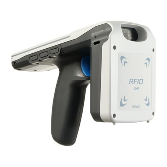
Chapter 1 Names and Functions Strap hole Use this hole when Code reading window attaching a hand strap. A window to read two-dimensional code such as QR Code, and barcode Battery cover Battery cover lock Beep sound emitting hole Trigger switch RF tag antenna Push this switch when reading Communicates with RF tag. -
Page 15: Description On Each Operating Part
1.1 Description on each operating part Button Operation Description To power ON, press the button for one second or more when the power is OFF. Powers ON/OFF To power OFF, press the button for three seconds or Power button more when the power is ON. Press this button swiftly (for less than one second), and Checks battery power level. -
Page 16: Description On Each Indicator
1.2 Description on each indicator Indicator Status Description Red, illuminating While communicating with RF tag Blue, illuminating RF tag/code reading is completed. Red, blinking (High speed, 3 times) RF tag communication error (*1) Red, blinking (Middle speed, 3 times) Data transfer error (*2) Red, blinking (Middle speed, continuously) Device error (*2) Status indicator... -
Page 17: Description On Each Buzzer
1.3 Description on each buzzer Function Status Description 4times (ON 70ms、OFF 70ms) Power On 5times (ON 100ms、OFF 100ms)、 Detection of the battery deterioration Power 3min interval, Battery power level: Less than 10% 5times (ON 100ms、OFF 100ms)、 High freq, 1time (ON 480ms) Power Off Short time, 1time (ON 80ms) Code reading is completed. -
Page 18: Chapter 2 Basic Operations
Chapter 2 Basic Operations 2.1 Loading the Batteries When you purchase the scanner, a battery is not installed. Install it in the following procedure. Press down and slide the battery cover lock ① in the direction indicated by the arrow. Remove the battery cover. ② Confirm the direction of a battery and an electrode. - Page 19 When replacing batteries, open the battery cover and pull out the battery using the strap. Before replacing batteries, be sure to power off the scanner. Notice on installing the battery. ・Remove the battery from the scanner and store it if not using the scanner for an extended period of time.
-
Page 20: Battery Charging
2.2 Battery Charging When you purchase the scanner, a battery has not been fully charged. You need to charge the battery using the dedicated Charging Cradle. Be sure to power off the scanner before charging. Charging the scanner Connect the output plug of the AC adapter into the DC input connector of the CU. - Page 21 Power indicator on the scanner Power indicator Power indicator Status Red, solid Charging Green, solid Charging completed Red, blink Charging error (Charging will stop) No light Charger is not correctly connected Charging the spare battery Set a spare battery to this cradle. Spare battery charging Check the direction of electrode and push indicator...
- Page 22 Use of USB Direct Cable Connect the Direct Cable to a power adaptor such as a USB charger or a USB port in a host computer. It may take long to charge to full depending on the power supply capacity of the host computer. Fasten the USB Direct Cable to the lower end of the scanner.
- Page 23 Notice of Charging ●Charging temperature ・Charging the battery at room temperature (18°C to 25°C) is recommended in order to deliver optimal performance. Please note that battery charging stops when ambient temperature drops below 0°C or exceeds 40°C. ●If the power indicator of the scanner blinks red, this indicates the circumstances described below. Please take any appropriate action.
-
Page 24: Powering On/Off
2.3 Powering ON/OFF Turning the scanner on Press and hold the power button of the scanner for one second or more. The beeper sounds, the power indicator turns on (indicating the battery level), and the scanner powers on. For the battery level, see "Battery Power Level Indicator". Turning the scanner off Press and hold the power button of the scanner for three seconds or more. - Page 25 Paring Implement the pairing in the slave mode as described below. ® Enable the Bluetooth function of the host terminal to enable the detection. For details, refer to the User's Manual of the host terminal. ® Power on the scanner, and the pairing indicator will blink in blue and the Bluetooth function will be enabled a little later.
-
Page 26: Scanning Codes
2.5 Scanning Codes Follow the procedure below to scan codes. (1) Move the code reading window close to the code, and then either start from the user application or press the trigger switch. Light for scanning is irradiated. (2) When the scanning is successfully completed, the status indicator will illuminate in blue and the beeper will be sounded. - Page 27 When codes cannot be scanned successfully Cause Measure Adjust an angle between the code printed surface and the scanner, and try again. When the light is focused on the printed surface of the code from Specular directly above, the scanner may reflection not read the code due to specular reflection.
-
Page 28: Reading/Writing Rf Tags
2.6 Reading/Writing RF Tags Read or write RF tags in accordance with the procedures described below. (1) Point the RF tag antenna toward the RF tag, and then either start from the host user application or press the trigger switch. The status indicator illuminates in red and the radio wave is emitted to the RF tag. - Page 29 Notice on RF tag reading/writing ・Radio wave is used when reading/writing RF tag. Therefore, the peripheral metallic objects and devices using radio wave (e.g. mobile phone, ham radio, and microwave oven) may deteriorate the reading performance of the scanner. When using the scanner, keep the above mentioned items as far away as possible.
- Page 30 When an RF tag cannot be read/written correctly Cause Measure Effect of metal When an RF tag is placed on a Keep an RF tag 15 cm or more away from metal plate, it may not be a metal plate. read/written.
-
Page 31: Battery Power Level Indicator
2.7 Battery Power level Indicator The battery power level can be checked with the power indicator by pressing the power button swiftly. The battery power is displayed in 3 levels. Level: 40% or more: Illuminating in green 39% to 10 %: Illuminating in orange Less than 10%: Illuminating in red The battery power level indicator shows only a rough estimate of battery power and does not show an accurate remaining power level. -
Page 32: Attaching The Host Terminal
2.8 Attaching the Host Terminal 2.8.1 Attachment for BHT-1800 Install the attachment for BHT-1800 series in the following procedure. Prepare the attachment for BHT-1800 series Attachment (separately sold). locking area Slide the attachment all the way to the end in the arrow direction along the rails on both sides of the scanner. - Page 33 When removing the attachment from the scanner, push the attachment as shown on the right, remove it’s locked area, and slide it. Note: Do not remove the attachment with your finger caught in the locked area. Doing so could damage the device. Cautions on installing the BHT-1800 ...
- Page 34 ® Attach the adaptor supported by QUAD LOCK (separately sold) as shown on the right to install. When removing, follow the procedure shown on the right. 。 When removing the attachment from the scanner, push the attachment as shown on the right, remove it’s locked area, and slide it.
- Page 35 Troubleshooting Guide Problem The scanner does not power on. ・Make sure that the battery is properly inserted into the scanner. ・Check the battery power level and charge the battery if necessary. ・Wipe any dirt from the battery and scanner terminals. Problem The scanner cannot be charged.
-
Page 36: Chapter 3 Parameters And Defaults
Chapter 3 Parameters and Defaults The parameters in the table below can be set with application software. Please refer to " DENSO SP1 SDK for Android API Reference Manual" for setting contents and setting method. (1) Common parameters Descripiton Parameter... - Page 37 (3) RFID parameter Descripiton Parameter RF Trigger mode Continuous mode 1 Read power dBm 30dBm Write power dBm 30dBm All channels enabled Channel Q param Session flag Session init Disabled Polarization Both vertical and horizontal Power save Disabled Double reading Disabled Write verify No verify...
-
Page 38: Appendix 1. Specifications
(∗1) Function settings may be subject to restrictions in some countries.. (∗2) To use SQRC outside of Japan, contact your Denso Wave representative. (∗3) These operating times are reference values measured under room temperature and other conditions set by our company. Actual operating times depend on working conditions. - Page 39 (∗5) Sharp temperature change, dewing or freezing not allowed, wet-bulb temperature 30°C max. (∗6) This is a test value obtained under room temperature conditions. It is not a guaranteed value.
-
Page 40: Appendix 1. Specifications(2)
Appendix 1. Specifications(2) RFID characteristics Country Freq. in MHz RF power Remarks Europian Union 865 - 868 2W ERP or less Link profile4,5 : 0.5W ERP or less Uinted States of America 902 - 928 4W EIRP or less Canada 902 - 928 4W EIRP or less Australia... - Page 41 θ= 0°、90° y *1: This is not a guaranteed value but a reference value measured by using DENSO WAVE specified tag (AVERY DENNISON AD-229r6). It is applicable when the center of RF tag exists within the range where arrows indicate in the figure.
- Page 42 *2: Define α, β, θ as follows. α Z Elevation angle α -α β -β Tilt angle β Z θ -θ Skew angle θ *3: Communication when writing in the RF tag When controlling the RF tag for writing, the RF tag communication range tends to be narrow in comparison with the case when reading RF tag.
-
Page 43: Appendix 2. Bluetooth® Glossary
Appendix 2. Bluetooth® Glossary ® The table below lists Bluetooth communication terms used in this manual. ® ® Bluetooth Address Bluetooth Device Address. ® (Bluetooth Device Address) ® Each Bluetooth device is allocated a unique 48-bit device address (BD_ADDR) ® defined by the Bluetooth SIG. -
Page 44: Appendix 3. Cu-Sp1A Specifications
Appendix 3. CU-SP1A Specifications (1) Hardware Input voltage 12V DC Dimensions 110 x 158 x 84 mm Weight Approx. 295g Current Consumption 2.5A(at 12V DC) Operating temperature 0~40℃ Storage temprature -10~60℃ unit[mm] (2) Charging time Charging SP1 BT-180LA approx. 3.5 hours BT-SP1L approx. - Page 45 RF Tag Handy Scanner SP1-QUBi User’s Manual 2nd Edition, January 2020...
Need help?
Do you have a question about the SP1-QUBi and is the answer not in the manual?
Questions and answers