
Related Manuals for AFi KATRINA


Summary of Contents for AFi KATRINA
- Page 1 BLOOD BANK CENTRIFUGE 6x1000ml 4x2000ml Maintenance Manual - Revision 1.0 - English version...
- Page 2 602922 This document has been prepared with the utmost care. However, AFI Centrifuge refuses to accept any responsibility in the event of errors or omissions. The same applies to any damage arising from the use of information contained in this manual.
- Page 3 Note: Used for important information Potential electrical hazard, only qualified person to access Biological hazard, Protective earth for user safety Lead Free Original Instructions - Rev.1.0 Service Manual– KATRINA centrifuge 2/ 54...
- Page 4 Updates Date Revision Modification Paragraph Author 10/03/2020 Creation F. Boucard Original Instructions - Rev.1.0 Service Manual– KATRINA centrifuge 3/ 54...
-
Page 5: Table Of Contents
STANDARD EXCHANGE OF COMPONENTS....................41 ..............................41 AFETY ULES & ............................41 PARE PARTS TOOLS ..............................41 ETTINGS FORM FUNCTIONAL CHECKS ..........................44 ............................44 ECHANICAL AFETY – P ...................... 44 LECTRICAL INSTALLATION ROTECTIVE EARTH Original Instructions - Rev.1.0 Service Manual– KATRINA centrifuge 4/ 54... - Page 6 ..............................45 PEED HECK ............................45 HECKING THE IMER ..........................45 HECKING THE EMPERATURE ANNEXES ..............................46 ............................. 46 ETURN AUTHORIZATION Original Instructions - Rev.1.0 Service Manual– KATRINA centrifuge 5/ 54...
- Page 7 Do not operate a centrifuge until all necessary safety measures have been taken. KATRINA centrifuge is designed in such a way that its use does not expose the operator and his environment to any danger.
- Page 8 Forbbiden use KATRINA is not designed for the following uses and environments: The following are considered prohibited: • Flammable materials, • Explosive substances, • Materials that can react causing a danger, • Toxic materials • Radioactive materials • Contaminated material not contained in an aerosol-tight container.
-
Page 9: Technical Specifications
1 Description of the Centrifuge 1.1 Technical specifications: Original Instructions - Rev.1.0 Service Manual– KATRINA centrifuge 3/ 54... - Page 10 Original Instructions - Rev.1.0 Service Manual– KATRINA centrifuge 4/ 54...
-
Page 11: External Parts Description
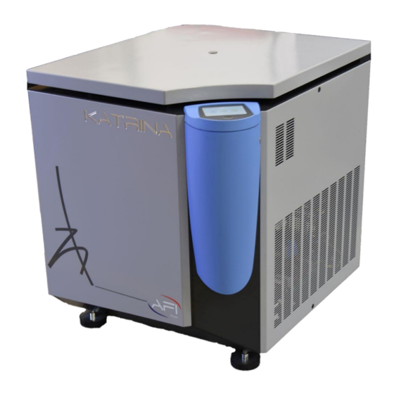
Main switch / circuit braker Condensor grid Hole for Emergency opening tool Fig. 3 Control panel Membrane Top ogive & membrane Display screen / touch pad Start / Stop button Open button Original Instructions - Rev.1.0 Service Manual– KATRINA centrifuge 5/ 54... -
Page 12: Exploded Views
Ogive 230V / 50 hz 71124005 Left side lateral panel 3/4 rear view Main switch / circuit breaker 71154012 Front view Feet (x4) Front view Bowl Bowl seal 71124001 Motor seal 71124002 Original Instructions - Rev.1.0 Service Manual– KATRINA centrifuge 6/ 54... -
Page 13: Accessories
1.4 Accessories Original Instructions - Rev.1.0 Service Manual– KATRINA centrifuge 7/ 54... -
Page 14: Internal Parts Description
Latch for right side Viewport Temperature sensor 71124007 Plastic inner lid Right side Electronic control center 71124005 Braking resistor Filter board 71124009 Solenoid valve coil Motor contactor 71124011 “Tachometer” board 71124008 Original Instructions - Rev.1.0 Service Manual– KATRINA centrifuge 8/ 54... - Page 15 Right side – low part details Motor and low suspension Motor 71124004 Low suspension foam Shock absorbers Shock absorbers 71124003 High suspension High suspension foam Front side Lid lock motor Lid lock system 71124006 Compressor Original Instructions - Rev.1.0 Service Manual– KATRINA centrifuge 9/ 54...
- Page 16 Left side Acces to condenser, behind grid Left side Drier filter Liquid receiver tank Condenser Lid locking system Overview Open position sensor Lid locking system details Motoreducer Original Instructions - Rev.1.0 Service Manual– KATRINA centrifuge 10/ 54...
- Page 17 Locked position sensor 1 Latch presence sensor Lid approach sensor Locking motor supply board 71124010 Gas spring 71124000 Original Instructions - Rev.1.0 Service Manual– KATRINA centrifuge 11/ 54...
- Page 18 Speed sensor 71124013 Bottom view 1.6 Service tools Here are the required tools for KATRINA service opertions : Tool Picture Tool Picture 3mm 4mm and 6mm Condenser bruch hexagonal wrench set with spherical head Insulated PZ2 screw dirver Condenser fins...
-
Page 19: Wiring Diagram
Specific gear Programming cable Mini USB cable Delivered with KATRINA 6mm hexagonal wrench 8mm hexagonal wrench (*)For accurate measurement, please use only properly calibrated measuring tools. 1.7 Wiring diagram next page Original Instructions - Rev.1.0 Service Manual– KATRINA centrifuge 13/ 54... -
Page 21: Refrigeration Circuit
1.8 Refrigeration circuit Original Instructions - Rev.1.0 Service Manual– KATRINA centrifuge 2/ 54... -
Page 22: Electronic Control Center / Block
This board supplies 24Vdc to the lid lock moto reducer when opening or closing is required. It receives 230V at mains input, this voltage is provided by the Electronic Control Center only when required. Original Instructions - Rev.1.0 Service Manual– KATRINA centrifuge 20/ 54... -
Page 23: Transformer
The board and especially the molded transformer are protected by a 2ATT 250V 5x20 fuse cartridge. 1.10 Transformer A toroid transformer is connected to the power board and provides 3 different voltages identified by the following colors: Tension 18.5 V Colour Green Yellow Black Original Instructions - Rev.1.0 Service Manual– KATRINA centrifuge 21/ 54... -
Page 24: Locking / Unlocking System
A safety system prevents the motoreducer from being energized if a speed signal is detected. This prevents the lid from being open is rotor is rotating. Original Instructions - Rev.1.0 Service Manual– KATRINA centrifuge 22/ 54... -
Page 25: Motor
“ERROR 04” is displayed. 1.13 Speed sensor KATRINA Speed sensor is a Hall Effect magnetic sensor, located under the motor. Six (6) magnets with alternating poles are arranged around a rotating disc. The sensor measures the frequency of passage of the magnets, and microcontroller determines the speed. -
Page 26: Vibrations Absorption / Suspension
A good balancing of the accessory is a key point to achieve satisfying separation quality. 1.19 Refrigeration System: KATRINA refrigeration system allows to maintain the samples temperature at their initial temperature while rotating. Temperature target can be set between -10°C and 40°C. -
Page 27: Proper Installation
21Arms can be drawn for less than 1mn during centrifuges acceleration under heaviest load and with maximal acceleration rate. KATRINA must be directly connected to the distribution board and protected by its own protection device. This device must be identified as the centrifuges' disconnector device and easily accessible in the immediate vicinity of the centrifuge. -
Page 28: Troubleshooting
Check the electrical supply / protection of the laboratory and restore it. Centrifuge display remains SUB D9 cap improperly Turn Centrifuge OFF. frozen at turn On, AFI logo is connected to the programming displayed but logging menu is slot at the bottom of the never displayed... - Page 29 NO SPEED The speed sensor is working The speed cannot be read within the first 30s of the cycle. SIGNAL AT improperly. Contact a certified technician START tachometer board working improperly. Original Instructions - Rev.1.0 Service Manual– KATRINA centrifuge 27/ 54...
- Page 30 Disconnect the probe from the micro controller board and measure the resistance. The value must be 500+ - 100 Ohm (PT500 sensor) RESERVED RESERVED RESERVED Original Instructions - Rev.1.0 Service Manual– KATRINA centrifuge 28/ 54...
-
Page 31: Cleaning And Lubrication
Clean any durt on the shaft and under the rotor. lay a thin layer of alimentary grease on the motor shaft Reassemble the rotor on the motor shaft with the provided wrench. Original Instructions - Rev.1.0 Service Manual– KATRINA centrifuge 29/ 54... -
Page 32: Settings
This menu is reserved for authorized technicians. 1st page of settings : Next page Setting the temperature probe Setting the imbalance sensitivity Setting the time delay of the lock Auto-Diagnostic Reset to factory settings Original Instructions - Rev.1.0 Service Manual– KATRINA centrifuge 30/ 54... - Page 33 Clear the counters 2nd settings page Previous page Changing the internal numbers Changing the counters Over Temperature Alarm Acceleration profiles edition Deceleration profiles edition Original Instructions - Rev.1.0 Service Manual– KATRINA centrifuge 31/ 54...
-
Page 34: Setting The Temperature Probe
7. Place the 100 gram weight in the same bucket. 8. Proceed in the same way as for the 100 gram weight. 9. The low threshold is then determined. (e.g. “520”) Original Instructions - Rev.1.0 Service Manual– KATRINA centrifuge 32/ 54... - Page 35 The 50 gr imbalance must be tolerated. Repeat the Low threshold check 3 times: Each cycle should take place normally. Note : This setting value is viewable in HOME -> INFORMATION menu Original Instructions - Rev.1.0 Service Manual– KATRINA centrifuge 33/ 54...
-
Page 36: Setting The Lock
The lock is in closed position when the marks on the deadbolt and the crankshaft are aligned. Unlocking steps : The steps are in the reverse order of the locking operation. The motor reducer rotates in the opposite direction. Original Instructions - Rev.1.0 Service Manual– KATRINA centrifuge 34/ 54... - Page 37 Note : These setting values are viewable in HOME -> INFORMATION menu. Original Instructions - Rev.1.0 Service Manual– KATRINA centrifuge 35/ 54...
-
Page 38: Auto-Diagnostic
Press Start/Stop: Change of state. "Start button" Disconnect the motor over temperature sensor, (intermediate "Motor Temp." connector in front of the motor contactor) Check ths state change Exit with the cross. Original Instructions - Rev.1.0 Service Manual– KATRINA centrifuge 36/ 54... -
Page 39: Information Update
Enter the counters modification menu Press the item to change. The input keyboard then appears. Fill in the value recorded from the old control center. Repeat this for all counts. Exit Original Instructions - Rev.1.0 Service Manual– KATRINA centrifuge 37/ 54... -
Page 40: Overtemperature Alarm Menu
50 ° C, then the cycle is aborted with the message ERROR 3. 5.9 Firmware update KATRINA centrifuge is controlled by 2 firmwares: • A firmware application called “Display firmware”, loaded into the screen board. It manages a HMI (Human Machine Interface), and visual screens. -
Page 41: Factory Reset
Continue?" OK to continue "Do not power off unit during reset." Wait until the following message. Turn off & turn on the unit. Original Instructions - Rev.1.0 Service Manual– KATRINA centrifuge 39/ 54... -
Page 42: Clearing Counters
"Warning: This will erase all internal counters, including centrifugation cycles counters, and error counters. This should be achieved in specific cases. Keep a record of the current settings before proceeding. Continue?" OK to continue Original Instructions - Rev.1.0 Service Manual– KATRINA centrifuge 40/ 54... -
Page 43: Standard Exchange Of Components
In case of electronic control center replacement, If the state of the control center allows to get them, record the values in the tables below. Programs : Name Speed Duration Temperature Acceleration Braking Original Instructions - Rev.1.0 Service Manual– KATRINA centrifuge 41/ 54... - Page 44 / 12: / 13: / 14: / 15: / 16: / 17: / 18: / 19: / 20 : Postcool ROTOR Pre-cooling Mode Enter service LOCKING TEMPO Original Instructions - Rev.1.0 Service Manual– KATRINA centrifuge 42/ 54...
- Page 45 UNLOCKING TEMPO IMBALANCE SETTING Original Instructions - Rev.1.0 Service Manual– KATRINA centrifuge 43/ 54...
-
Page 46: Functional Checks
Wear 7.2 Electrical installation – Protective earth In order to protect user against electric shock, KATRINA protective earth conductor must always be properly connected to the installation. This must be checked at least once a year, using a certified continuity tester. - Page 47 4. Start the previously defined test cycle 5. Wait for the end of the cycle and centrifuge’s full stop. 6. Open the lid and check the tubes water temperature, it must be 4°C +/-2°C Original Instructions - Rev.1.0 Service Manual– KATRINA centrifuge 45/ 54...
- Page 48 The guarantee will not be applicable in case of mishandling of the user or deteriorated items due to misuse (for more details, see our general conditions of sale). Original Instructions - Rev.1.0 Service Manual– KATRINA centrifuge 46/ 54...
- Page 49 Original Instructions - Rev.1.0 Service Manual– KATRINA centrifuge 47/ 54...
- Page 50 Original Instructions - Rev.1.0 Service Manual– KATRINA centrifuge 48/ 54...
- Page 51 Original Instructions - Rev.1.0 Service Manual– KATRINA centrifuge 49/ 54...
- Page 52 Original Instructions - Rev.1.0 Service Manual– KATRINA centrifuge 50/ 54...
- Page 53 Original Instructions - Rev.1.0 Service Manual– KATRINA centrifuge 51/ 54...
- Page 54 Tél : +33(0)2 43 06 66 76 contact@ afigroups.com www.afigroups.com Non-contractual photo. All rights reserved, including photos and illustrations. Copyright ® Société AFI Centrifuge – SIRET 513 982 645 00022. Original Instructions - Rev.1.0 Service Manual– KATRINA centrifuge 52/ 54...
Need help?
Do you have a question about the KATRINA and is the answer not in the manual?
Questions and answers