Table of Contents
Advertisement
Quick Links
Advertisement
Table of Contents

Related Manuals for AFi ISA AFI-CI060V Series


Summary of Contents for AFi ISA AFI-CI060V Series
- Page 1 Maintenance Manual - Revision 1.1 - English version...
- Page 2 602697 This document has been prepared with the utmost care. However, AFI Centrifuge refuses to accept any responsibility in the event of errors or omissions. The same applies to any damage arising from the use of information contained in this manual.
- Page 3 Claims under this warranty should be directed to AFI Centrifuge. Setting forth in detail the nature of the defect, the date of the initial installation and the serial and model number of the equipment.
-
Page 4: Table Of Contents
............................23 HECKING THE IMER ) ..................... 23 HECKING THE EMPERATURE EFRIGERATED MODEL ELECTRICAL DIAGRAMS...........................24 0.6 L : ISA / AFI-CI060V & AFI-CI060V-E ............... 24 ITER ENTILATED ODEL SERIES 0.6 L : ISA / AFI-CI060R & AFI-CI060R-E ............25 ITER... - Page 5 Updates Date Revision Modification Paragraph Author 2019 August 27 Creation LSO / FBO 2020 Jun 6th Modification – Temperature Check Original Instructions - Rev.1.0 Service Manual– ISA Centrifuges 4/ 27...
-
Page 6: Description Of The Centrifuge
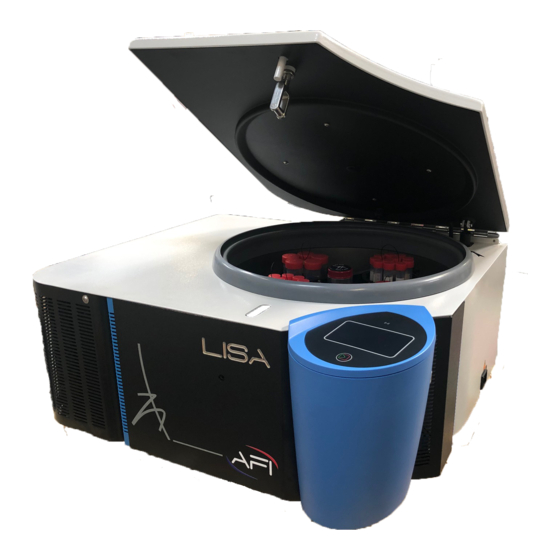
References Model AFI-CI060V Ventilated, 120V / 60Hz AFI-CI060V-E Ventilated, 230V / 50-60Hz Refrigerating, 120V / 60Hz AFI- CI060R Refrigerating, 230V / 50Hz AFI- CI060R-E The centrifuge is composed of: • an electrical block, called Ogival Control Center • a lock •... - Page 7 Validation Button validation button is the following one , Logo Short press Press & hold ISA series Setting controls Values can be directly adjusted using the front panel Knob Logo ISA series Lid Opening Button The lid opening is controlled by the button on the right side of the Control Center. Electronic microcontroller Board The electronic microcontroller board is located under the display card.
-
Page 8: Lock
1.2 Lock Description ISA / AFI-CI060 series are equipped with an electric lid opening. Lid closing is a manual operation Visual Description (1) Lid latch, permanent magnet equipped. (2) Hook. (3) Pendulum. (4) Microswitch contact (ILS sensor). (5) Cogwheel (3x) :... - Page 9 Unlocking the lid Visual Description The lid is locked : The pendulum (3) maintains the hook (2) in its position. Fig. 5 Lock back view – Locked position When activated, the ratchet cogwheel (5a) pushes the pendulum (3). Fig. 6 Ratchet cogwheel pushing pendulum Pendulum (3) is completely pushed.
-
Page 10: Motor
1.3 Motor Three phases induction motor powered in variable voltage & frequency. It has an integrated over temperature sensor. It measures the heating of the internal motor winding, and sends a signal from 130 degrees Celsius. Centrifuge then display error code “# 04”. 1.4 Speed sensor The speed sensor is a Hall Effect magnetic sensor, placed under the motor. -
Page 11: Absorption Of Vibrations
1.8 Absorption of vibrations Any system has its own resonance frequency, which will cause oscillations. The dissipative elements of these oscillations, which translate into vibrations, are anti-vibration mounts, numbering 3. This set will allow for absorbing parasitic movements whatever the rotor, its load, and its speed, providing that the load is balanced. Those 3 shock absorbers are placed vertically between the motor and the stabilizer bed. -
Page 12: Troubleshooting & Messages
2 Troubleshooting & Messages 2.1 Troubleshooting Error Codes / Description Cause Solution Reserved Not used code IMBALANCE Buckets don't swing freely. Clean the rotor trunions and corresponding areas on buckets. Apply a thin film of supplied grease on these locations. Cf. § Erreur ! Source du renvoi introuvable. - Page 13 Motor is diconnected / not Contact an authorized technician. properly connected The power board is not able to feed the motor Contact an authorized technician SPEED SIGNAL LOST The speed sensor is working The speed signal was lost more than 6s during improperly.
-
Page 14: Reminder Messages
2.2 Reminder messages According machine status, recall message are displayed.They are composed of a message number & a logo. Message Logo Cause Solution Command The rotor needs to be greased after Dispense synthetic grease 200 cycles runs. following Erreur ! Source du renvoi introuvable. -
Page 15: Settings
3 Settings 3.1 Access to parameters Advanced parameters To access to advanced parameters menu, follow instructions: Action on ISA Instruction Effect Press & hold START/STOP button to switch to sleep mode. Press & hold validation button & press The software revision is displayed. START button to access to advanced parameters. - Page 16 Number of lid openings (lid motor activation) Last error code Last detected error (*) high speed means: > 4500 RPM Service parameters To access to service parameters, follow instructions: When reaching L7 code in advanced parameters (cf. previous paragraph), press & hold validation button. Action on ISA Instruction Effect Press &...
- Page 17 Service parameters Availability Value range Default values Buttons sensitivity (START / STOP & Validation button) Speed sensor feedback 6553 Lid locked sensor feedback Open button feedback PFC Feedback Lid motor test Motor over temperature Compressor starting test Potentiometer on knob angle Power driver temp / fault feedback 5000 Power driver current feedback...
- Page 18 Operating Service parameters (Setting) Sensitivity of START/STOP & validation buttons, the higher the value, the more the sensibility of the button increases (Diagnostic) : Open the lid. Tachometer diagnostic With b5 parameter displayed, turn manually the rotor. The speed is displayed on the screen.
-
Page 19: Unbalancing Sensitivity Setting
Unbalancing Sensitivity Setting The centrifuge has a reaction to the load balancing faults which may be different depending on the media on which the centrifuge is placed. Check following items before any setting adjustment: Balanced bucket loadings, Installation instructions, conform to User Manual, Visual inspection, Cleaning rotor trunions &... -
Page 20: Setting The Time Delay Of The Lock
3.3 Setting the Time Delay of the lock See Tech note, attached with lid lock service kit. 3.4 Loading the firmware Required material : USB flash drive / stick, in FAT 32 format. Max. size : 32 GB. 1 firmware file in *.bin format Note : Take care to let the firmware file as unique file on root directory of USB drive. -
Page 21: Spare Parts & Tools
4.3 Spare parts & tools Isa / AFI-CI060 series – 0.6 Liter Model Technote References Name V + R 230V 71101001 Gas spring kit – ISA V 71101002 Power “rack” – 230V kit 71101003 Power “rack” – 120V kit 71101004 Electronic control center with µC board... -
Page 22: Setting Form
4.4 Setting form Before Factory reset, recort your program settings in board as below : Prog # Speed Rpm/rcf Duration Hh:min / Temperature °C/°F Acceleration Braking min:sec slope slope Advanced parameters : Advanced Description Value parameters Imbalance setting Temperature offset Countdown starting at speed End of cycle sound signal Alarm sound signal... -
Page 23: Functional Checks
5 Functional checks 5.1 Safety • Hinge: Check the tightness of the screws, and the integrity of the hinge by moving side-to-side. There should be no movement other than that of the hinge rotation. • Control Center: The Control Center must be secured by a nut located near the switch and fixed to the body of the centrifuge. -
Page 24: Speed Check
5.2 Speed Check Required equipment: Calibrated and reflective adhesive optical tachometer. Place a reflective strip on the central part of the rotor. Remove the plug sealing the central porthole under the lid. Close lid. Start a cycle at the desired speed When the setpoint speed is reached, place the speedometer on the central porthole. -
Page 25: Electrical Diagrams
6 Electrical diagrams 6.1 0.6 Liter Ventilated Model : ISA / AFI-CI060V & AFI-CI060V-E series Original Instructions - Rev.1.0 Service Manual– ISA Centrifuges 24/ 27... -
Page 26: Series
6.2 0.6 Liter Refrigerating Model : ISA / AFI-CI060R & AFI-CI060R-E series Original Instructions - Rev.1.0 Service Manual– ISA Centrifuges 25/ 27... -
Page 27: Refrigerating System
7 Refrigerating System 7.1 0.6 Liter 120V / 230V Model / ISA – AFI-CI060R-E Original Instructions - Rev.1.0 Service Manual– ISA Centrifuges 26/ 27... -
Page 28: Annexes
8 Annexes 8.1 Return authorization Return authorization N° A return number will be provided after contacting us. In order to process your file, we ask you to return this document duly completed by you. This document must be affixed outside the package. Within 72 hours upon receipt of material, we will send you an acknowledgment of receipt.After diagnosis by our technicians, we will send you a quote. -
Page 29: Software Update
8.2 Software update Step 1: copy the new firmware file to a USB flash drive / stick / pen « ISAYXXXX.bin » The USB stick has to be FAT32 formatted and no more than 32gB capacity The file shall be copied to the root directory and be the only file at this location Step 2: Access the advance parameters menu in order to check the... - Page 30 Step 5: Plug the centrifuge to the mains. Programming automatically starts after a few seconds Knob backlighting is red and blinking all along the programming process and turns to solid green once completed. Step 6: Wait for Knob backlight to turn to solid green and Unplug the centrifuge Programming Completed...
- Page 31 3, rue Nicolas Copernic ZA Nord Bazouges 53200 CHATEAU-GONTIER FRANCE Tél : +33(0)2 43 06 66 76 contact@ afigroups.com www.aficentrifuge.com Non-contractual photo. All rights reserved, including photos and illustrations. Copyright ® Société AFI Centrifuge – SIRET 513 982 645 00022.
Need help?
Do you have a question about the ISA AFI-CI060V Series and is the answer not in the manual?
Questions and answers