Advertisement
Quick Links
E
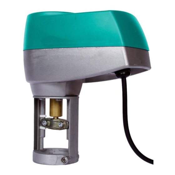
inführung
Die VA1000. Ventilantriebs- Baureihe hat eine
Kraft von 1000 N. Sie werden verwendet, um
Ventile in HVAC Systemen zu steuern. Dieser
neue Antrieb ist selbstjustierend und hat deshalb
eine
sehr
geringe
Inbetriebnahmezeit.
mechanische Handausrastung und sind in 24VAC,
230VAC 3-Punkt sowie stetiger Regelfunktion
erhältlich. Die Ventilantriebe VA1000. sind für die
Johnson Flansch- Ventilbaureihen VG9000 PN6 &
PN10, sowie für die Baureihen VG8000 PN16 und
die Schraubventile VGS800N PN16 vorgesehen.
Mit diesem Antrieb sind maximale Schließdrücke
dieser Ventilbaureihen gesichert. Alle Antriebe sind
selbstjustierend und haben einen Hub von 7 mm
bis 49 mm.
Adaptionen
auf
andere
Anfrage.
selbstjustierend
Force controlled motor shut-off.
Manual override as standard.
Unique swing-gate yoke.
IP54 enclosure protection.
Delivered with fitted 1.5 m cable.
Status LED.
Models with optional aux. switches or 2 kΩ
feedback potentiometer.
Control-Signal failure - stem to pre-determined
position.
Stroke position indicator.
VA1000. Ventilantrieb
Montage-
Alle
Antriebe
haben
Ventilbaureihen
und
auf
VA1000.
Vorteile
kürzere Inbetriebnahmezeiten
Ensures that the maximum thrust has been
achieved.
Allows manual positioning independent of the
power supply on all models.
Allows lateral mounting of the actuator reducing
the vertical space over the valve needed for
installation.
Allows installation in a wide range of
environments.
Saves time and protects actuator during
installation.
Visual actuator status monitoring.
Provides potential free contacts for user
availability or independent monitoring of the
actuator's status.
Actuator pre-set position after a control signal
failure (extended/retracted), is selectable in-situ.
Automatic adjustment of stroke indicators at the
start of the first cycle.
Advertisement

Subscribe to Our Youtube Channel
Related Manuals for JOVENTA VA1000 Series


Summary of Contents for JOVENTA VA1000 Series
- Page 1 VA1000. Ventilantrieb inführung Die VA1000. Ventilantriebs- Baureihe hat eine Kraft von 1000 N. Sie werden verwendet, um Ventile in HVAC Systemen zu steuern. Dieser neue Antrieb ist selbstjustierend und hat deshalb eine sehr geringe Montage- Inbetriebnahmezeit. Alle Antriebe haben mechanische Handausrastung und sind in 24VAC, 230VAC 3-Punkt sowie stetiger Regelfunktion erhältlich.
- Page 2 VA1000. estellinformation estellbeispiel Das Ventil und der Antrieb werden separate Code No. Spannung bestellt, Wenn die Montage im Werk gewünscht ist, wird der Bestellcode zusätzlich mit einem +M Threaded coupler versehen. Floating Control Beispiel : Produkt 1 VGS8F1W1N (Ventilkörper) VA1000.2 230 V AC Produkt 2 VA1000.1 (Antrieb)
- Page 3 VA1000. peration Floating models Proportional models (0(2)…10 VDC or 0(4)…20 mA) Connections Actuator Stem Extends The VA1000. provides a proportional stroke Retracts corresponding to the control signal. No stroke adjustment is necessary due to the Following control signals are defined as standard: automatic force control.
- Page 4 VA1000. Control signal failure pre-set position Auto Calibration - Custom Signal Ranges (DIP SWITCH 3 = ON) (not functional with 0…20 mA control selected) (Max range limits 0…10 V DC or 0…20 mA) A control-signal failure on proportional models will Procedure: cause the actuator to automatically move the stem Condition: Actuator already mounted on valve.
- Page 5 VA1000. LED warnings Manual override When the crank is pushed into the hexagonal LED colour opening power is interrupted and manual operation is engaged. Turning the hand crank clockwise Status Green Yellow extends the stem and counter-clockwise retracts Indicates the stem. Pushing the hand crank down again Power on, motor 2nd incorrect disengages the manual operation and reconnects...
-
Page 6: Wiring Instructions
VA1000. pplications: Parallel and sequential operation Actuators without built-in positioner for Actuators with built-in positioner for controllers with PAT (Positioning Adjusting controllers with 0…10V output in parallel Time) output in parallel operation operation All actuators have the same nominal running 24 VAC Com 0-10 V speed (rate of travel), see specifications. -
Page 7: Iring Diagrams
VA1000. iring Diagrams Actuators are delivered with a fitted 1.5 m long cable. The cable numbering corresponds to the actuator terminal numbering as seen in the wiring diagram. Floating Models VA1000.1 24 V VA1000.2 230 V Orange Orange Blue Brown Black Black/Blue Black/Grey... - Page 8 VA1000. iring Diagrams Actuators are delivered with a fitted 1.5 m long cable. The cable numbering corresponds to the actuator terminal numbering as seen in the wiring diagram Proportional Models WARNING For 0(4)…20 mA control the grey wire must be moved from the 3V VA1000.1MS terminal to the 3A terminal! Max.
- Page 9 VA1000. imensions (in mm) M16, Ø 3.5...10 mm Cable length1.5 m...
-
Page 10: Specifications
Low voltage directive 73/23 EEC: EN 60730-1 The performance specifications are nominal and conform to acceptable industry standards. For application at conditions beyond these specifications, consult the local Joventa office. Joventa shall not be liable for damages resulting from misapplication or misuse of its products.
Need help?
Do you have a question about the VA1000 Series and is the answer not in the manual?
Questions and answers