Table of Contents
Advertisement
Quick Links
Tel +1 (717) 767-6511
Fax +1 (717) 764-0839
www.redlion.net
MODEL CUB5 - MINIATURE ELECTRONIC 8-DIGIT DUAL
U
L
C
US LISTED
US LISTED
4
IND. CONT . EQ.
51EB
GENERAL DESCRIPTION
The CUB5 provides the user the ultimate in flexibility, from its complete user
programming to the optional setpoint control and communication capability.
The meter can be programmed as a single or dual counter with rate indication
capability. The display can be toggled either manually or automatically between
the selected displays.
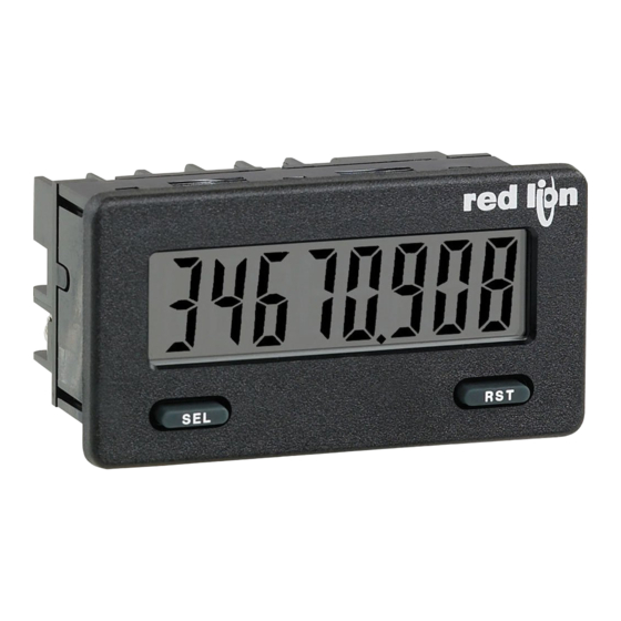
The CUB5 display has 0.46" (11.7 mm) high digits. The LCD is available in
two versions, reflective (CUB5R000) and backlight (CUB5B000). The
backlight version is user selectable for green or red backlighting with variable
display intensity.
The counter is programmable for one of eight different count modes,
including bi-directional and quadrature. When programmed as a dual counter,
each counter has a separate scale factor and decimal points. In the counter/rate
indicator mode, each have their own scaling and decimal point read-outs in
different engineering units. The internal batch counter can be used to count
setpoint output activations.
The meter has two separate inputs which provide different functions
depending on which operating mode is selected. Input A accepts the signal for
the Count and/or Rate displays, while Input B accepts the signal for the Count
display or direction control. In the anti-coincidence mode, both inputs are
monitored simultaneously so that no counts are lost. The resulting display can
be chosen as the sum or difference of the two inputs. The Rate Indicator has
programmable low (minimum) and high (maximum) update times to provide
optimal display response at any input frequency. There is a programmable user
input that can be programmed to perform a variety of functions.
The capability of the CUB5 can be easily expanded with the addition of
option modules. Setpoint capability is field installable with the addition of the
single setpoint relay output module or the dual setpoint solid state output
module. Serial communications capability for RS232 or RS485 is added with a
serial option module.
The CUB5 can be powered from an optional Red Lion Micro-Line/Sensor
Power Supply (MLPS1000), which attaches directly to the back of a CUB5. The
MLPS1 is powered from 85 to 250 VAC and provides up to 400 mA to drive the
unit and sensors.
DIMENSIONS In inches (mm)
COUNTER AND RATE INDICATOR
LCD, REFLECTIVE OR GREEN/RED LED BACKLIGHTING
0.46" (11.7 mm) HIGH DIGITS
OPTIONAL SETPOINT OUTPUT MODULES
OPTIONAL SERIAL COMMUNICATIONS MODULE (RS232 or RS485)
OPERATES FROM 9 TO 28 VDC POWER SOURCE
PROGRAMMABLE SCALING FOR COUNT AND RATE
BI-DIRECTIONAL COUNTING, UP/DOWN CONTROL
QUADRATURE SENSING (UP TO 4 TIMES RESOLUTION)
BUILT-IN BATCH COUNTING CAPABILITY
DISPLAY COLOR CHANGE CAPABILITY AT SETPOINT OUTPUT
NEMA 4X/IP65 SEALED FRONT BEZEL
COUNTER
The CUB5 receives incoming pulses and multiplies them by the Count Scale
Factor to obtain the desired reading for the count display. Input A accepts the
signal for the count and Input B is used for quadrature, dual counter, anti-
coincidence counting, or up/down control counting.
RATE
The rate indicator utilizes the signal at Input A to calculate the rate value
using a time interval method (1/tau). The unit counts on the negative edge of the
input pulses. After the programmed minimum update time elapses and the next
negative edge occurs, the unit calculates the input rate based on the number of
edges that occurred during the elapsed time. The input rate is then multiplied by
the rate scaling value to calculate the rate display.
At slower rates, averaging can be accomplished by programming the rate
minimum update time for the desired response. Extensive scaling capabilities
allow practically any desired reading at very slow count rates.
SAFETY SUMMARY
All safety related regulations, local codes and instructions that appear in this
literature or on equipment must be observed to ensure personal safety and to
prevent damage to either the instrument or equipment connected to it. If
equipment is used in a manner not specified by the manufacturer, the protection
provided by the equipment may be impaired.
Do not use this meter to directly command motors, valves, or other actuators
not equipped with safeguards. To do so can be potentially harmful to persons or
equipment in the event of a fault to the meter.
CAUTION: Risk of Danger.
Read complete instructions prior to
installationand operation of the unit.
Note: Recommended minimum clearance (behind the panel) for mounting clip installation is 2.15" (54.6) H x 3.00" (76.2) W.
1
Bulletin No. CUB5-F
Drawing No. LP0584
Released 1/08
CAUTION: Risk of electric shock.
Advertisement
Table of Contents

Related Manuals for Red Ion CUB5


Summary of Contents for Red Ion CUB5
- Page 1 RATE The CUB5 display has 0.46" (11.7 mm) high digits. The LCD is available in The rate indicator utilizes the signal at Input A to calculate the rate value two versions, reflective (CUB5R000) and backlight (CUB5B000). The using a time interval method (1/tau).
-
Page 2: Meter Specifications
NFORMATION TYPE MODEL NO. DESCRIPTION PART NUMBER CUB5R Dual Counter & Rate Indicator with Reflective Display CUB5R000 CUB5 CUB5B Dual Counter & Rate Indicator with Backlight Display CUB5B000 CUB5RLY Single Relay Option Card CUB5RLY0 CUB5SNK Dual Sinking Open Collector Output card... -
Page 3: Installation Environment
DUAL SINKING OUTPUT CARD (One or two setpoints) Type: Non-isolated switched DC, N Channel open drain MOSFET The CUB5 meters can be fitted with optional output cards and/or serial Current Rating: 100 mA max. communications cards. The details for the plug-in cards can be reviewed in the : 0.7 V @ 100 mA... -
Page 4: Plug -I N Cards
3.0 I NSTALLING ARDS The Plug-in cards are separately purchased option cards that perform specific CAUTION: The Plug-in cards and main circuit board contain static functions. The cards plug into the main circuit board of the meter. After sensitive components. Before handling the cards, discharge installing the cards, replace the rear cover before wiring the meter. -
Page 5: Input Wiring
4.3 INPUT WIRING CAUTION: Power common (PWR COMMON) is NOT isolated from input common (INP COMM). In order to preserve the safety of the meter application, the power common must be suitably isolated from hazardous live earth referenced voltage; or input common must be at protective earth ground potential. -
Page 6: Programming Menu
5.0 R EVIEWING THE RONT UTTONS AND ISPLAY DISPLAY MODE OPERATION ENTERING PROGRAM MODE PROGRAMMING MODE OPERATION Index display through enabled values Press and hold for 2 seconds to activate Store selected parameter and index to next parameter Advances through the program menu/ Resets count display(s) and/or outputs Increments selected parameter value or selection OPERATING MODE DISPLAY DESIGNATORS... -
Page 7: Parameter Menu
6.1 MODULE 1 - I NPUT ETUP ARAMETERS 1-INPUt PARAMETER MENU Shaded area selections only apply when Counter B is enabled (Dual Counter mode or batch counter). COUNTER A COUNT LOAD VALUE COUNT MODE CmtA Ld Cnt ud qUAd 1 Add Add INP A-b -9999999... - Page 8 SCALING FOR COUNT INDICATION USER INPUT FUNCTION The CUB5’s scale factor is factory set to 1, to provide one count on the USEr INP display for each pulse that is input to the unit. In many applications, there will not be a one-to-one correspondence between input pulses and display units.
- Page 9 INPUT FREQUENCY CALCULATION SCALING FOR RATE INDICATION The meter determines the input frequency by summing the number of falling To scale the rate, enter a Scaling Display value with a corresponding Scaling edges received during a sample period of time. The sample period begins on the Input value.
- Page 10 6.3 MODULE 3 - D ISPLAY AND RONT ANEL ARAMETERS 3-dSPLAY PARAMETER MENU FRONT PANEL DISPLAY SELECT ENABLE (SEL) PROGRAMMING SECURITY CODE SEL Enb Pro CodE selection allows the button to toggle through the enabled The Security Code determines the programming mode and the accessibility displays.
- Page 11 6.4 MODULE 4 - S ETPOINT UTPUT ARAMETERS 4-SEtPt PARAMETER MENU The Setpoint Output Parameters are only active when an optional Setpoint Output Module is installed in the meter. Some parameters in the menu will not appear depending on the Setpoint Assignment and Setpoint Output Action. The Setpoint Parameter Availability chart below illustrates this.
- Page 12 Setpoint. SPn ChC SETPOINT STANDBY OPERATION This parameter enables the backlight CUB5 to switch the backlight color when the output state changes. This parameter is only active for the backlight version. SPn StbY This parameter only applies to Low Acting Boundary Type setpoints.
- Page 13 6.5 MODULE 5 - S (5-SEriAL) ERIAL OMMUNICATIONS ARAMETERS PARAMETER MENU The Serial Communications Parameters are only accessible when an optional RS232 or RS485 serial communications module is installed in the meter. ABBREVIATED PRINTING This section replaces the bulletin shipped with the RS232 and RS485 serial communications plug-in cards.
- Page 14 Sending Serial Commands and Data Register Identification Chart Applicable When sending commands to the meter, a string containing at least one Value Description MNEMONIC Transmit Details (T and V) Commands command character must be constructed. A command string consists of a 8 digit positive/7 digit negative Counter A T, V, R...
-
Page 15: Limited Warranty
(0 to ). Each ASCII character is “framed” with a beginning start bit, receiving device. The CUB5 meter ignores the parity bit of incoming data and an optional parity bit and one or more ending stop bits. The data format and sets the parity bit to odd, even or none (mark parity) for outgoing data. - Page 16 CUB5 PROGRAMMING QUICK OVERVIEW...
Need help?
Do you have a question about the CUB5 and is the answer not in the manual?
Questions and answers