Advertisement
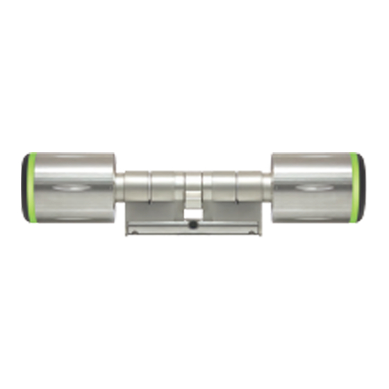
C-700 Series
Digital Locking
Modular Assembly Manual
Parts list for Tool Kit
Connect Bodies and pins:
5mm x 12, 10mm x 12, and 15mm x 4
Bridges: 30/35 x 6, 35/35 x 6, 35/40 x
6, 40/40 x 6, 40/45 x 3, and 45/45 x 3
Connect Body Set Screws: 35mm x
18, 40mm x 18, and 45mm x 6
Bridge Screws: 50pcs
Reader Knob Screws: 50pcs
Steel Balls: 50pcs
Anti-pulling Pins: 20pcs
Anti-drilling Pins: 20pcs
Seal Rings inside Reader Knob: 10pcs
Assembly Holder: 1pc
Knob Cap Assembly Tool: 1pc
WFE TECHNOLOGY CORPORATION
Tel: 886-4-22300362 Fax: 886-4-22377995
No. 16 Ke Yuan 2nd Rd., Central Taiwan Science Park
Taichung city 407, Taiwan.
E-mail: info@waferlock.com
Length Adjustment
1
Slide cylinder into assembly holder.
Loosen all screws on bridge with
flathead screwdriver.
2
Remove bridge from the top of
cylinder carefully. There are two steel
balls in between. Please keep steel
balls in a container to prevent from
loss during the length adjustment.
Inner Knob
Cam
Reader Knob
3
Take apart cylinder into three sections:
Reader Knob part, Cam, and Inner Knob
part.
★
There is size indicator on the bridge
body
pin
4
Select a specified length connect body
set or combination with screws for
Reader Knob part and Inner Knob part.
★
Please refer to Length Assembly Diagram
for connect body set selection.
5
Tighten screw of connect body set on
Reader Knob part and Inner Knob part
with Phillips screwdriver.
6
Assemble three parts: Reader Knob
part, Cam, and Inner Knob part.
7
Slightly turn reader knob and inner knob
to fit into cam.
Put steel balls back to the original
position.
Select appropriate bridge and assemble it.
8
Tighten bridge screws with flathead
screwdriver.
Advertisement
Table of Contents

Related Manuals for Waferlock C-700 Series


Summary of Contents for Waferlock C-700 Series
- Page 1 Length Adjustment C-700 Series Digital Locking Tighten screw of connect body set on Slide cylinder into assembly holder. Modular Assembly Manual Loosen all screws on bridge with Reader Knob part and Inner Knob part with Phillips screwdriver. flathead screwdriver. Remove bridge from the top of Assemble three parts: Reader Knob cylinder carefully.
- Page 2 Length Assembly Diagram 10mm 15mm 30mm Measurements indicated in mm 10 15 30 + 30 + + 5 15 10 15 5 15 5 15 10 15 30 +...
Need help?
Do you have a question about the C-700 Series and is the answer not in the manual?
Questions and answers