Nice TTN3724HS Instructions And Warnings For Installation And Use
Swing gate opener
Hide thumbs
Also See for TTN3724HS:
- Instructions and warnings for installation and use (16 pages) ,
- Quick manual (2 pages)
Table of Contents
Advertisement
Available languages
Available languages
Nice
TTN3724HS
TTN3724HSC
TTN3724RHS
TTN6024HS
TTN6024RHS
Swing gate opener
IT - Istruzioni ed avvertenze per l'installazione e l'uso
EN - Instructions and warnings for installation and use
FR - Instructions et avertissements pour l'installation et l'utilisation
ES - Instrucciones y advertencias para la instalación y el uso
PT - Instruções e avisos para instalação e uso
DE - Installations- und Bedienungsanleitung
NL - Aanwijzingen en aanbevelingen voor installatie en gebruik
PL - Instrukcje i ostrzeżenia w zakresie montażu i użytkowania
RU - Инструкции и важная информация для технических специалистов
Advertisement
Chapters
Table of Contents

Related Manuals for Nice TTN3724HS


Summary of Contents for Nice TTN3724HS
- Page 1 Nice TTN3724HS TTN3724HSC TTN3724RHS TTN6024HS TTN6024RHS Swing gate opener IT - Istruzioni ed avvertenze per l'installazione e l'uso EN - Instructions and warnings for installation and use FR - Instructions et avertissements pour l’installation et l’utilisation ES - Instrucciones y advertencias para la instalación y el uso PT - Instruções e avisos para instalação e uso...
-
Page 3: Table Of Contents
SOMMARIO AVVERTENZE GENERALI: SICUREZZA - INSTALLAZIONE - USO 1 - DESCRIZIONE PRODOTTO E DESTINAZIONE D’USO 2 - LIMITI D’IMPIEGO 3 - INSTALLAZIONE 3.1 - Sbloccare manualmente il motoriduttore 3.2 - Bloccare manualmente il motoriduttore 4 - COLLEGAMENTI ELETTRICI 5 - COLLAUDO DELL’AUTOMAZIONE 5.1 - Collaudo 5.2 - Messa in servizio 6 - ACCESSORI OPZIONALI... -
Page 4: Avvertenze Generali
• Le batterie devono essere eliminate in modo sicuro. • Se le batterie non sono ricaricabili non sostituirle con batterie ricaricabili. APPARECCHI CON LUCE A LED • Guardare la luce a LED da vicino e per un periodo prolungato può abbagliare la vista. Può ridurre temporaneamente le facoltà visive e causare incidenti. Non guardare direttamente i LED. APPARECCHI CON DISPOSITIVO RADIO • Nice S.p.A. fabbricante di questa apparecchiatura dichiara che è conforme alla direttiva 2014/53/UE. Il manuale di istruzioni ed il testo completo della dichiarazione di conformità UE è disponibile al seguente indirizzo Internet: www.niceforyou.com; alla sezione “supporto” e “download”. • Per i trasmettitori: 433MHz: ERP < 10dBm - 868MHz: ERP < 14dBm - 2.4 Ghz: EIRP < 10dBm. • Per i ricevitori: 433MHz, 868MHz. 2 – Italiano... -
Page 5: Descrizione Prodotto E Destinazione D'uso
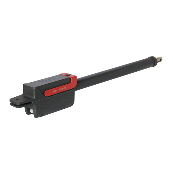
è da considerarsi improprio e vietato! È un motoriduttore elettromeccanico previsto nelle versioni: TTN3724HS - TTN3724HSC - TTN3724RHS - TTN6024HS - TTN6024RHS. È provvisto di un motore a corrente continua a 24 V e di un riduttore con vite senza fine. Il motoriduttore viene alimentato dalla centrale di comando esterna a cui deve essere collegato. ATTENZIONE! – Per i motoriduttori mod. TTN6024HS e TTN3724HS deve essere utilizzata esclusivamente la centrale di comando mod. MC824H! In caso d’interruzione dell’energia elettrica (black-out) è possibile muovere manualmente le ante del cancello sbloccando il motoriduttore (per i motoriduttori mod. TTN3724RHS e TTN6024RHS è possibile muovere manualmente l’anta senza sbloccare il motoriduttore). LIMITI D’IMPIEGO Attenzione! - L’installazione del motore deve essere effettuata da personale qualificato, nel rispetto di leggi, norme, regolamenti... -
Page 6: Installazione
Importante! Prima di eseguire l’installazione del prodotto verificare capitolo 2 e capitolo 9 (caratteristiche tecniche). La fig. 1 mostra il contenuto dell’imballo: verificare il materiale. La fig. 2 mostra la posizione dei vari componenti di un impianto tipico con accessori Nice: A - motoriduttori elettromeccanici B - elettroserratura verticale C - coppia di fotocellule D - coppia finecorsa meccanici (in Apertura) E - colonne per fotocellule F - segnalatore lampeggiante G - selettore a chiave o tastiera digitale H - centrale di comando modello TTN3724RHS - TTN6024RHS: MC824HR modello TTN3724HS - TTN6024HS: MC824H modello TTN3724HSC - TTN6024HS: MC824HHS 4 – Italiano... - Page 7 AVVERTENZE • Un’installazione errata può causare gravi ferite alla persona che esegue il lavoro e alle persone che utilizzeranno l’impianto. Individuare la posizione di fissaggio della staffa posteriore e anteriore Fissare la staffa posteriore secondo le quote d’installazione verificando che sia in bolla Fissare il motoriduttore sulla staffa posteriore Italiano – 5...
-
Page 8: Sbloccare Manualmente Il Motoriduttore
Sbloccare manualmente il motoriduttore (manovra manuale) Estrarre completamente lo stelo Assemblare provvisoriamente la staffa anteriore all’anta del cancello Verificare che il motoriduttore sia in bolla poi fissare lo stelo alla staffa anteriore 6 – Italiano... - Page 9 Verificare manualmente che: - in posizione di apertura massima il cancello si fermi sui finecorsa meccanici - il movimento dell’anta sia regolare e privo di attriti Eventualmente eseguire interventi correttivi affinché il movimento risulti soddisfacente a - Sganciare lo stelo dalla staffa anteriore b - Fissare definitivamente quest’ultima all’anta c - Fissare definitivamente lo stelo alla staffa anteriore Italiano – 7...
-
Page 10: Bloccare Manualmente Il Motoriduttore
Bloccare il motoriduttore Ripetere l’operazione per entrambi i motoriduttori. 3.1 - Sbloccare manualmente il motoriduttore (manovra manuale) Alzare il tappo di gomma Inserire la chiave di sblocco fornita e ruotarla in senso orario di 90° Ripetere l’operazione per entrambi i motoriduttori. 3.2 - Bloccare manualmente il motoriduttore (manovra manuale) Posizionare manualmente l’anta del cancello a metà della sua corsa Alzare il tappo di gomma Inserire la chiave di sblocco e ruotarla in senso anti-orario di 90° Ripetere l’operazione per entrambi i motoriduttori. 8 – Italiano... -
Page 11: Collegamenti Elettrici
COLLEGAMENTI ELETTRICI ATTENZIONE! – Un collegamento errato può provocare guasti o situazioni di pericolo; quindi, rispettare scrupolosamente i collegamenti indicati. – Eseguire le operazioni di collegamento con l’alimentazione elettrica scollegata. Togliere il coperchio al motoriduttore (a) Allentare il passacavo (b) e inserire il cavo di collegamento (c) Collegare i vari cavi e il cavo di terra nell’apposito occhiello ENCODER ENCODER MOTOR MOTOR Italiano – 9... -
Page 12: Collaudo Dell'automazione
Stringere il pressacavo e rimettere il coperchio COLLAUDO DELL’AUTOMAZIONE Queste sono le fasi più importanti nella realizzazione dell’automazione al fine di garantire la massima sicurezza. Il collaudo può essere usato anche come verifica periodica dei dispositivi che compongono l’automatismo. Il collaudo dell’intero impianto deve essere eseguito da personale esperto e qualificato che deve farsi carico delle prove richieste, in funzione del rischio presente e di verificare il rispetto di quanto previsto da leggi, normative e regolamenti, ed in particolare tutti i requisiti della norma EN12445 che stabilisce i metodi di prova per la verifica degli automatismi per cancelli. 5.1 - Collaudo Ogni singolo componente dell’automatismo (bordi sensibili, fotocellule, arresto di emergenza, ecc.) richiede una specifica fase di collaudo; per questi dispositivi si dovranno eseguire le procedure riportate nei rispettivi manuali istruzioni. Eseguire il collaudo come segue: Verificare che sia stato rispettato rigorosamente quanto previsto nel presente manuale ed in particolare nel capitolo 1 Sbloccare manualmente il motoriduttore Verificare che sia possibile muovere manualmente l’anta in apertura e in chiusura con una forza non superiore a 390 N (circa 40 kg) Bloccare manualmente il motoriduttore Collegare l’alimentazione elettrica Utilizzando i dispositivi di comando o arresto previsti, eseguire delle prove di apertura, chiusura ed arresto del cancello e verificare che il comportamento corrisponda a quanto previsto Verificare il corretto funzionamento di tutti i dispositivi di sicurezza presenti nell’impianto e verificare che il comportamento del cancello corrisponda a quanto previsto Comandare una manovra di chiusura e verificare la forza dell’impatto dell’anta contro la battuta del finecorsa meccanico. Se necessario provare a scaricare la pressione per una migliore regolazione... -
Page 13: Accessori Opzionali
Dichiarazione di Conformità UE (N. 605/TITAN) e dichiarazione di incorporazione di “quasi macchina” Revisione: 3 - Lingua: IT - Nome produttore: NICE S.p.A. - Indirizzo: Via Callalta n°1, 31046 Oderzo (TV) Italy - Persona autorizzata a costituire la documentazione tecnica: NICE S.p.A. - Tipo di prodotto: Motoriduttore elettromeccanico - Modello/Tipo: TTN3724H SC,TTN3724HS,TTN3724RHS, TTN6024HS, TTN6024RHS - Accessori: Fare riferimento al catalogo. Il sottoscritto Roberto Griffa in qualità di Amministratore Delegato, dichiara sotto la propria responsabilità che il prodotto sopra indicato risulta conforme alle disposizioni imposte dalle seguenti direttive: • Direttiva 2014/30/UE (EMC): EN 61000-6-2:2019 - EN 61000-6-3:2007+A1:2011... -
Page 14: Smaltimento Del Prodotto
ATTENZIONE! - I regolamenti vigenti a livello locale possono prevedere pesanti sanzioni in caso di smaltimento abusivo di questo prodotto. CARATTERISTICHE TECNICHE DEL PRODOTTO Tutte le caratteristiche tecniche riportate, sono riferite ad una temperatura ambientale di 20°C (± 5°C). • Nice S.p.A. si riserva il diritto di apportare modifiche al prodotto in qualsiasi momento lo riterrà necessario, mantenendone comunque la stessa funzionalità e destinazione d’uso. MODELLO TTN3724HS TTN3724HSC TTN6024HS TTN3724RHS TTN6024RHS Tensione motore Frequenza Lunghezza max anta... -
Page 15: Avvertenze Finali E Sblocco
AVVERTENZE FINALI E SBLOCCO Si consiglia di conservare questa guida. AVVERTENZE • Sorvegliare il cancello in movimento e tenersi a distanza di sicurezza finchè il cancello non si sia completamente aperto o chiuso; non transitare nel passaggio fino a che il cancello non sia completamente aperto e fermo. •... - Page 17 CONTENTS GENERAL WARNINGS: SAFETY - INSTALLATION - USE 1 - PRODUCT DESCRIPTION AND INTENDED USE 2 - OPERATING LIMITS 3 - INSTALLATION 3.1 - Manually releasing the gearmotor 3.2 - Manually locking the gearmotor 4 - ELECTRICAL CONNECTIONS 5 - AUTOMATION TESTING 5.1 - Testing 5.2 - Commissioning 6 - OPTIONAL ACCESSORIES 7 - MAINTENANCE CE DECLARATION OF CONFORMITY 8 - DISPOSAL OF THE PRODUCT 9 - TECHNICAL SPECIFICATIONS...
- Page 18 • For drive motors that allow for accessing unprotected moving parts once they have been installed, such parts must be installed 2.5 m above the floor or other surface form which they can be accessed. • Make sure to avoid any entanglements due to the opening movement of the driven part. • After the installation, make sure that the mechanism is correctly adjusted and that the protection system and the manual release device (if present) work properly. BATTERY-OPERATED DEVICES • The device must be disconnected from the power supply when removing the batteries. • The batteries must be removed from the device prior to its disposal. • The batteries must be safely disposed of. • If the batteries are not rechargeable, do not replace them with rechargeable batteries. APPLIANCES WITH LED LIGHT • Looking at LED lights from close up and for prolonged periods can cause dazzling. It may temporarily reduce eyesight and cause accidents. Avoid look- ing at LEDs directly. APPLIANCES WITH RADIO DEVICE • The manufacturer of this appliance, Nice S.p.A., hereby declares that the product complies with Directive 2014/53/EU. The instruction manual and the full text of the EU Declaration of Conformity are available at the following Internet address: www.niceforyou.com, under the “support” and “download” sections. • For transmitters: 433 MHz: ERP < 10 dBm - 868 MHz: ERP < 14 dBm - 2.4 Ghz: EIRP < 10 dBm. • For receivers: 433 MHz, 868 MHz. 2 – English...
-
Page 19: Product Description And Intended Use
The product is an electromechanical gearmotor, available in two versions: TTN3724HS - TTN3724HSC - TTN3724RHS - TTN6024HS - TTN6024RHS. It is equipped with a 24V motor and a worm screw reduction unit. The gearmotor is powered off the external control unit to which it is connected. WARNING! – With the gearmotors mod. TTN6024HS and TTN3724HS, only the control unit model MC824H can be used! In case of power outage, the gate can be operated manually by disengaging the gearmotor (for gearmotor models TTN3724RHS and TTN6024RHS the gate leaf can be moved manually without disengaging the gearmotor). APPLICATION LIMITS Caution! - The motor must be installed by qualified personnel in compliance with current legislation, standards and regulations, and the directions provided in this manual. -
Page 20: Installation
Important! Before installing the product, refer to chapters 2 and 9 (technical specifications). Fig. 1 shows the contents of the package: check the material. Fig. 2 shows the location of the various components of a typical sys- tem mounting Nice accessories: A - electromechanical gearmotors B - vertical electric lock C - photocell pair D - mechanical limit switch pair (opening) E - photocell pillars F - flasher G - keyswitch/digital keypad H - control unit model TTN3724RHS - TTN6024RHS: MC824HR model TTN3724HS - TTN6024HS: MC824H model TTN3724HSC - TTN6024HS: MC824HHS 4 – English... - Page 21 WARNINGS • Incorrect installation may cause serious physical injury to those working on or using the system. Identify the front and rear bracket mounting positions Secure the rear bracket with reference to its specified installation positions and check that it lies level Mount the gearmotor to the rear bracket English – 5...
- Page 22 Manually release the gearmotor (manual manoeuvre) Pull the rod completely out Provisionally locate the front bracket onto the gate Check that the gearmotor is level, then fit and secure the rod to the front bracket 6 – English...
- Page 23 Check manually that: - when the gate is fully open, it halts against its mechanical stops - the gate swings freely and without resistance Correct any defects a - Unhook the rod from the front bracket b - Mount the latter to the gate permanently c - Permanently mount the rod to the front bracket English – 7...
-
Page 24: Manually Releasing The Gearmotor
Lock the gearmotor Follow this procedure for both gearmotors. 3.1 - Manually releasing the gearmotor (manual manoeuvre) Raise the rubber cap Fit the provided wrench and rotate it CW by 90° Follow this procedure for both gearmotors. 3.2 - Manually locking the gearmotor (manual manoeuvre) Move the gate to the halfway open position by hand Raise the rubber cap Fit the provided wrench and rotate it CCW by 90° Follow this procedure for both gearmotors. 8 – English... -
Page 25: Electrical Connections
ELECTRICAL CONNECTIONS CAUTION! – Incorrect connections can cause faults or hazards; therefore ensure that the specified connections are strictly observed. – Hook up the unit with the electrical power shut off. Remove the gearmotor’s cover (a) Loosen the cable clamp (b) and run the cable through it (c) Hook up the cables and connect the earth cable to its eyebolt ENCODER ENCODER MOTOR MOTOR English – 9... -
Page 26: Automation Testing
Tighten down the cable clamp and put the cover back on AUTOMATION TESTING These are the most important stages in the automation’s construction in order to ensure maximum safety. Testing can also be adopted as a method for periodically checking that all the various devices in the system are functioning correctly. Testing of the entire system must be performed by qualified and experienced personnel who must establish which tests to conduct on the basis of the risks involved, and verify the compliance of the system with applicable regulations, legislation and standards, in particular with all the provisions of EN12445 which establishes the test methods for automation systems for gates. 5.1 - Testing Each component of the system, (safety edges, photocells, emergency stop, etc.) requires a specific testing phase. To do so, follow the proce- dures given in the instruction manuals. Run the test as follows: Ensure that the instructions outlined in this manual and in particular in chapter 1 have been observed in full. Manually release the gearmotor Make sure you can move the door manually both during opening and closing with a force of max. 390 N (40 kg approx.). Manually lock the gearmotor Hook up the electrical power supply Use the control or stop devices to test the opening, closing and stopping of the gate and that it behaves as intended. Check the operation of all safety devices, and check that the gate performs as it should. Activate a closing manoeuvre and check impact force of the door against the mechanical stop. If necessary, reduce the pressure for better adjustment If the dangerous situations caused by the movement of the gate have been made safe by limiting the impact force, the user must measure the impact force according to EN12445. Note – The gearmotor’s torque cannot be adjusted directly: this adjustment is done by the control unit. 5.2 - Commissioning Commissioning may only be done when all the gearmotor tests specified in par. 5.1, and those of the other equipment, have been passed: to commission the unit, refer to the control unit manual. -
Page 27: Optional Accessories
Check the wear of all moving parts and replace any worn components Connect the power supplies up again, and run all the tests and checks described in Chapter 4 For the other equipment in the system, refer to its user manuals. EU Declaration of Conformity (N. 605/TITAN) and declaration of incorporation of “partly completed machinery” Revision: 3 - Language: EN - Name of manufacturer: NICE S.p.A. - Address: Via Callalta n°1, 31046 Oderzo (TV) Italy - Person au- thorised to draw up the technical documentation: NICE S.p.A. - Type of product: Electromechanical gearmotor - Model/Type: TTN 3724HSC,TTN3724HS,TTN3724RHS, TTN6024HS, TTN6024RHS - Accessories: Refer to the catalog. The undersigned, Roberto Griffa, in the role of Chief Executive Officer, declares under his sole responsibility, that the product specified above conforms to the provisions of the following directives: • Directive 2014/30/EU (EMC): EN 61000-6-2:2019 - EN 61000-6-3:2007+A1:2011 • Directive 2011/65/UE (RoHS II) The product also complies with the following directives according to the requirements envisaged for “partly completed machinery” (Annex... -
Page 28: Disposal Of The Product
As indicated by the symbol, the product may not be disposed of as domestic waste. Sort the materials for disposal, according to the methods envisaged by current legislation in your area, or return the product to the retailer when purchasing an equivalent product. CAUTION! – Local legislation may envisage serious fines in the event of abusive disposal of this product. TECHNICAL SPECIFICATIONS All technical specifications stated in this section refer to an ambient temperature of 20°C (± 5°C). • Nice S.p.A. reserves the right to apply modifications to products at any time when deemed necessary, while maintaining the same intended use and functionality. MODEL TTN3724HS TTN3724HSC TTN6024HS TTN3724RHS TTN6024RHS Motor voltage Frequency Max gate length Max gate weight... -
Page 29: Precautions - Releasing And Locking
PRECAUTIONS - RELEASING AND LOCKING This user guide should be stored. WARNINGS • Keep at a safe distance from the moving gate until it is completely open or closed; do not transit through the gate until it is completely open and has come to a standstill. •... - Page 31 SOMMAIRE INSTRUCTIONS GÉNÉRALES : SÉCURITÉ - INSTALLATION - UTILISATION 1 - DESCRIPTION DU PRODUIT ET APPLICATION 2 - LIMITES D’UTILISATION 3 - INSTALLATION 3.1 - Débrayer manuellement le motoréducteur 3.2 - Bloquer manuellement le motoréducteur 4 - RACCORDEMENTS ÉLECTRIQUES 5 - ESSAI DE L’AUTOMATISME 5.1 - Essais 5.2 - Mise en service 6 - ACCESSOIRES OPTIONNELS 7 - MAINTENANCE DE L’AUTOMATISME DÉCLARATION DE CONFORMITÉ...
-
Page 32: Instructions Générales : Sécurité - Installation - Utilisation
• Les portes et portails verticaux nécessitent une fonction ou un dispositif antichute. • Pour les motorisations qui permettent d’accéder à des parties en mouvement non protégées après leur installation, il faut que ces parties soient instal- lées à plus de 2,5 m au-dessus du sol ou d’un autre niveau qui permette d’y accéder. • Veiller à éviter tout piégeage dû au mouvement d’ouverture de la partie guidée. • Après l’installation, s’assurer que le mécanisme est correctement réglé et que le système de protection et tout déverrouillage manuel fonctionnent cor- rectement. APPAREILS AVEC BATTERIES • Il faut débrancher l’appareil de l’alimentation électrique lors du retrait des batteries. • Retirer toujours les batteries avant de mettre l’appareil au rebut. • Les batteries doivent être éliminées de façon appropriée. • Si les piles ne sont pas rechargeables, ne pas les remplacer par des piles rechargeables. APPAREILS AVEC LUMIÈRE LED • Fixer la lumière LED de près et longtemps peut éblouir. La faculté visuelle peut être temporairement réduite, ce qui peut provoquer des accidents. Ne pas regarder directement les LEDs. APPAREILS AVEC DISPOSITIF RADIO • Nice S.p.A., fabricant de cet appareil, déclare que le produit est conforme à la directive 2014/53/UE. Le manuel d’instructions et le texte intégral de la déclaration de conformité UE est disponible à l’adresse Internet suivante : www.niceforyou.com, dans la section « support » et « téléchargement ». • Pour les émetteurs : 433Mhz : ERP < 10dBm - 868Mhz : ERP < 14dBm - 2.4 Ghz : EIRP < 10dBm. • Pour les récepteurs : 433MHz - 868MHz. 2 – Français... -
Page 33: Description Du Produit Et Application
être considérée comme impropre et interdite ! Le réducteur électromécanique est prévu en deux versions : TTN3724HS - TTN3724HSC - TTN3724RHS - TTN6024HS - TTN6024RHS. Il est doté d’un moteur à courant continu de 24 V et d’un réducteur avec vis sans fin. Le motoréducteur est alimenté par la centrale de commande externe à laquelle il doit être connecté. ATTENTION ! – Pour les motoréducteurs mod. TTN6024HS et TTN3724HS, il faut utiliser exclusivement la centrale de commande mod. MC824H ! En cas de coupure de courant, il est possible d’ouvrir les portes manuelles en débrayant le réducteur (il est possible de déplacer manuellement le vantail sans débrayer l’opérateur pour les opérateurs mod. TTN3724RHS et TTN6024RHS). LIMITES D’UTILISATION Attention ! - L’installation du moteur doit être effectuée par du personnel qualifié, dans le respect des lois, des normes et des règle-... -
Page 34: Installation
Important ! Avant d’effectuer l’installation du produit, contrôler les données des chapitres 2 et 9 (caractéristiques techniques). La fig. 1 illustre le contenu de l’emballage : contrôler le matériel. La fig. 2 illustre la position des différents composants d’une installation standard avec accessoires Nice : A - motoréducteurs électromécaniques B - verrouillage électrique vertical C - couple de photocellules D - couple de butées mécaniques (ouverture) E - colonnes pour photocellules F - clignotant G - sélecteur à clé ou clavier numérique H - centrale de commande modèle TTN3724RHS - TTN6024RHS: MC824HR modèle TTN3724HS - TTN6024HS: MC824H modèle TTN3724HSC - TTN6024HS: MC824HHS 4 – Français... - Page 35 AVERTISSEMENTS • Une installation incorrecte peut causer de graves blessures aux personnes qui effectuent le travail et à celles qui utiliseront le produit. Repérer la position de fixation de la barre arrière et avant Fixer la barre arrière selon les indications, en vérifiant qu’elle est à niveau Fixer le motoréducteur sur la barre arrière Français – 5...
- Page 36 Débloquer manuellement le motoréducteur (manœuvre manuelle) Extraire complètement la tige Assembler la barre avant au vantail du portail S’assurer du nivellement correct du motoréducteur, puis fixer la tige à la barre arrière 6 – Français...
- Page 37 Vérifier manuellement : - qu’en position d’ouverture maximale, le portail se ferme sur les butées mécaniques - que le mouvement du battant est régulier et qu’il n’y a pas de frottement Éventuellement, prendre des mesures correctives pour que le mouvement soit satisfaisant a - Décrocher la tige de la barre avant b - La fixer définitivement au battant c - Fixer définitivement la tige à la barre avant Français – 7...
-
Page 38: Débrayer Manuellement Le Motoréducteur
Verrouiller le motoréducteur Répéter l’opération pour les deux motoréducteurs. 3.1 - Débrayer manuellement motoréducteurs (manœuvre manuelle) Soulever le bouchon en caoutchouc Insérer la clé de débrayage fournie et la tourner dans le sens des aiguilles d'une montre à 90° Répéter l’opération pour les deux motoréducteurs. 3.2 - Bloquer manuellement motoréducteurs (manœuvre manuelle) Placer manuellement le vantail du portail à mi-course Soulever le bouchon en caoutchouc Insérer la clé de débrayage fournie et la tourner dans le sens contraire des aiguilles d'une montre à 90° Répéter l’opération pour les deux motoréducteurs. 8 – Français... -
Page 39: Raccordements Électriques
RACCORDEMENTS ÉLECTRIQUES ATTENTION ! – Une connexion incorrecte peut provoquer des pannes ou des situations de danger ; respecter par conséquent scrupuleusement les connexions indiquées. – Effectuer les raccordements avec le courant coupé. Retirer le couvercle de l’opérateur (a) Desserrer le passe-câble (b) et insérer le câble de raccordement (c) Raccorder les différents câbles et le câble de terre dans l’œillet prévu à cet effet ENCODER ENCODER MOTOR MOTOR Français –... -
Page 40: Essai De L'automatisme
Serrer le serre-câble et remettre le couvercle ESSAI DE L’AUTOMATISME Il s’agit des phases les plus importantes dans la réalisation de l’automatisation afin de garantir la sécurité maximum. L’essai peut être utilisé également comme vérification périodique des dispositifs qui composent l’automatisme. L’essai de toute l’installation doit être effectué par du personnel qualifié et expérimenté qui devra se charger d’établir les essais prévus en fonction des risques présents et de vérifier le respect de ce qui est prévu par les lois, les normes et réglementations et en particulier, toutes les conditions de la norme EN 12445 qui détermine les méthodes d’essai pour la vérification des automatismes de portails. 5.1 - Essais Chaque élément de l’automatisme (bords sensibles, photocellules, arrêt d’urgence, etc.) demande une phase spécifique d’essai ; pour ces dispositifs, il faudra effectuer les procédures figurant dans les manuels d’instructions respectifs. Effectuer l’essai de la façon suivante : Vérifier que tout ce qui est prévu dans le présent manuel, notamment au chapitre 1, est rigoureusement respecté. Débloquer manuellement le motoréducteur. Vérifier qu’il est possible de manœuvrer manuellement le portail en ouverture et en fermeture avec une force ne dépassant pas 390 N (environ 40 kg). Bloquer manuellement le motoréducteur. Raccorder l'alimentation électrique. En utilisant les dispositifs de commande ou d’arrêt prévus, effectuer des essais d’ouverture, de fermeture et d’arrêt du portail et vérifier que le comportement du portail correspond à ce qui est prévu. Vérifier un par un le fonctionnement correct de tous les dispositifs de sécurité présents dans l’installation et vérifier que le comporte- ment du portail correspond à ce qui est prévu. Commander une manœuvre de fermeture et vérifier la force d’impact de la porte contre la butée de fin de course mécanique. Si nécessaire, essayer de réduire la pression pour un meilleur réglage. Si les risques liés au mouvement du vantail n'ont pas été résorbés par la limitation de la force d'impact, il faut effectuer la mesure de la force suivant les prescriptions de la norme EN 12445. -
Page 41: Accessoires Optionnels
Déclaration de conformité UE (N. 605/TITAN) et déclaration d’incorporation de « quasi-machines » Révision : 3 - Langue : IT - Nom du fabricant : NICE S.p.A. - Adresse : Via Callalta n°1, 31046 Oderzo (TV) Italy - Personne habilitée à rédiger la documentation technique : NICE S.p.A. - Type de produit : Motoréducteur électromécanique - Modèle/Type : TTN3724 HSC,TTN3724HS,TTN3724RHS, TTN6024HS, TTN6024RHS - Accessoires : Reportez-vous au catalogue Je soussigné, Roberto Griffa, en qualité de Chief Executive Officer, déclare sous mon entière responsabilité que le produit susmentionné est... -
Page 42: Mise Au Rebut Du Produit
ATTENTION ! – Les règlements locaux en vigueur peuvent prévoir de lourdes sanctions en cas d’élimination prohibée de ce produit. CARACTÉRISTIQUES TECHNIQUES DU PRODUIT Toutes les caractéristiques techniques indiquées se réfèrent à une température ambiante de 20 °C (± 5 °C). • Nice S.p.A. se réserve le droit d’apporter des modifications au produit à tout moment si elle le juge nécessaire, en garantissant dans tous les cas les mêmes fonctions et le même type d’utilisation prévu. MODÈLE TTN3724HS TTN3724HSC TTN6024HS TTN3724RHS TTN6024RHS Tension moteur Fréquence Longueur maxi. du vantail Poids maxi. -
Page 43: Recommandations - Débrayer Et Bloquer
RECOMMANDATIONS - DÉBRAYER ET BLOQUER Il est conseillé de conserver cette notice. RECOMMANDATIONS • Surveiller le portail en mouvement et se tenir à une distance de sécurité tant qu’il n’est pas complètement ouvert ou fermé ; ne pas transiter dans le passage tant que le portail n’est pas complètement ouvert ou fermé. •... - Page 45 ÍNDICE ADVERTENCIAS GENERALES: SEGURIDAD - INSTALACIÓN - USO 1 - DESCRIPCIÓN DEL PRODUCTO Y DESTINO DE USO 2 - LÍMITES DE EMPLEO 3 - INSTALACIÓN 3.1 - Desbloquear manualmente el motorreductor 3.2 - Bloquear manualmente el motorreductor 4 - CONEXIONES ELÉCTRICAS 5 - PRUEBA DE LA AUTOMATIZACIÓN 5.1 - Prueba 5.2 - Puesta en servicio 6 - ACCESORIOS OPCIONALES 7 - MANTENIMIENTO DE LA AUTOMATIZACIÓN...
-
Page 46: Advertencias Generales
• Las puertas y cancelas verticales requieren una función o un dispositivo anticaída. • En el caso de los motores de accionamiento que permiten el acceso a partes en movimiento no protegidas, éstas deben estar instaladas a más de 2,5 m del pavimento o por encima de cualquier otro nivel que pueda permitir el acceso. • Asegurarse de evitar atrapamientos debidos al movimiento de apertura de la parte guiada. • Después de la instalación asegurarse de que el mecanismo esté regulado correctamente y el sistema de protección y el eventual desbloqueo manual fun- cionen correctamente. APARATOS CON BATERÍAS • Antes de sacar las baterías es necesario desconectar el aparato de la alimentación eléctrica. • Antes de desechar el aparato hay que quitarle las baterías. • Las baterías se deben desechar de manera segura. • Si las baterías no son recargables, no sustituirlas con baterías recargables. APARATOS CON LUZ LED • La fijación de la vista en la luz LED de cerca durante un lapso prolongado puede enceguecer. Pueden reducirse temporalmente las facultades visuales y pueden ocurrir accidentes. No mirar directamente a los LED. APARATOS CON DISPOSITIVO RADIO • El fabricante Nice S.p.A. declara que este aparato es conforme a la directiva 2014/53/UE. El manual de instrucciones y el texto completo de la declaración de conformidad UE está disponible en la siguiente dirección Internet: www.niceforyou.com; sección “soporte” y “descarga”. • Para los transmisores: 433MHz: ERP < 10dBm - 868MHz: ERP < 14dBm - 2.4 Ghz: EIRP < 10dBm. • Para los receptores: 433MHz, 868MHz. 2 – Español... -
Page 47: Descripción Del Producto Y Destino De Uso
Es un motorreductor electromecánico que se suministra en dos versiones: TTN3724HS - TTN3724HSC - TTN3724RHS - TTN6024HS - TTN6024RHS. Consiste en un motor para corriente continua a 24 V y un reductor con tornillo sinfín. ¡ATENCIÓN! – Para los motorreductores mod. TTN6024HS y TTN3724HS debe utilizarse exclusivamente la central de mando mod. MC824H! En caso de corte de suministro eléctrico, es posible mover las hojas manualmente desbloqueando el motorreductor (con los motorreductores mod. TTN3724RHS y TTN6024RHS es posible mover la hoja manualmente sin desbloquear el motorreductor). LÍMITES DE EMPLEO ¡Atención! - El motor debe ser instalado por personal cualificado, respetando las leyes, las normas y los reglamentos, además de... -
Page 48: Instalación
La fig. 2 muestra la posición de los distintos componentes de una instalación típica con accesorios Nice: A - motorreductores electromecánicos B - electrocerradura vertical C - par de fotocélulas D - par de topes mecánicos (en apertura) E - columnas para fotocélulas F - señal intermitente G - selector de llave o teclado digital H - central de mando modelo TTN3724RHS - TTN6024RHS: MC824HR modelo TTN3724HS - TTN6024HS: MC824H modelo TTN3724HSC - TTN6024HS: MC824HHS 4 – Español... - Page 49 ADVERTENCIAS • Una instalación incorrecta podría provocar heridas graves a la persona que realice el trabajo y a las personas que utilicen el sistema. Identificar la posición de fijación de la brida posterior y delantera Fijar la brida posterior según las distancias de instalación comprobando que quede nivelada Fijar el motorreductor sobre la brida posterior Español – 5...
- Page 50 Desbloquear manualmente el motorreductor (maniobra manual) Extraer completamente el vástago Ensamblar provisoriamente la brida delantera a la hoja de la cancela Comprobar que el motorreductor esté bien nivelado y fijar el vástago a la brida delantera 6 – Español...
- Page 51 Comprobar manualmente que: - en posición de apertura máxima, la cancela se detenga en los topes mecánicos - el movimiento de la hoja sea regular y sin roces Corregir hasta que el movimiento sea adecuado a - Desenganchar el vástago de la brida delantera b - Fijarla definitivamente a la hoja c - Fijar el vástago definitivamente a la brida delantera Español – 7...
-
Page 52: Desbloquear Manualmente El Motorreductor
Bloquear el motorreductor Realizar la misma operación con ambos motorreductores. 3.1 - Desbloquear manualmente el motorreductor (maniobra manual) Levantar el tapón de goma Poner la llave de desbloqueo y girarla 90° en sentido horario Realizar la misma operación con ambos motorreductores. 3.2 - Bloquear manualmente el motorreductor (maniobra manual) Levar la hoja de la cancela manualmente hasta la mitad de su recorrido Levantar el tapón de goma Poner la llave de desbloqueo y girarla 90° en sentido antihorario Realizar la misma operación con ambos motorreductores. 8 – Español... -
Page 53: Conexiones Eléctricas
CONEXIONES ELÉCTRICAS ¡ATENCIÓN! – Una conexión incorrecta podría provocar averías o situaciones peligrosas: respetar estrictamente las conexiones indicadas. – Ejecutar las operaciones de conexión con la alimentación eléctrica desconectada. Sacar la tapa del motorreductor (a) Aflojar el pasacable (b) y poner el cable de conexión (c) Conectar todos los cables y el cable de tierra en el ojal correspondiente ENCODER ENCODER MOTOR MOTOR Español – 9... -
Page 54: Prueba De La Automatización
Apretar el prensaestopas y poner la tapa PRUEBA DE LA AUTOMATIZACIÓN Estas son las etapas más importantes en la realización de la automatización para garantizar la seguridad máxima. La prueba puede realizarse a modo de control periódico de los dispositivos que componen la automatización. La prueba de toda la instalación debe ser efectuada por personal cualificado y experto, el cual deberá establecer los ensayos previstos de acuerdo con los riesgos presentes y comprobar que se respeten las leyes, normativas y reglamentos, especialmente todos los requisitos de la norma EN 12445, que establece los métodos de prueba de las automatizaciones para cancelas. 5.1 - Prueba Cada componente de la automatización (bandas sensibles, fotocélulas, parada de emergencia, etc.) requiere un fase de prueba específica; por lo tanto, se deberán seguir los diferentes procedimientos indicados en los respectivos manuales de instrucciones. Ejecutar la prueba de la siguiente manera: Comprobar que hayan sido respetadas estrictamente las indicaciones dadas en este manual y especialmente aquellas del capítulo 1 Desbloquear manualmente el motorreductor Comprobar que sea posible abrir y cerrar manualmente la hoja con una fuerza que no supere los 390 N (alrededor de 40 kg) Bloquear manualmente el motorreductor Conectar la alimentación eléctrica Utilizando los dispositivos de mando o de parada previstos, efectuar pruebas de apertura, cierre y parada de la cancela y verificar la respuesta correcta Verificar el funcionamiento correcto de todos los dispositivos de seguridad incorporados en la instalación, comprobando la respuesta correcta de la cancela Activar una maniobra de cierre y verificar la fuerza de impacto de la hoja contra el tope mecánico. De ser necesario, descargar la presión para mejorar la regulación Si las situaciones peligrosas causadas por el movimiento de la hoja se han prevenido limitando la fuerza de impacto, hay que medir... -
Page 55: Accesorios Opcionales
Comprobar que las conexiones roscadas estén bien apretadas Controlar el desgaste de las piezas móviles y sustituir las piezas desgastadas Conectar las fuentes de alimentación eléctrica y ejecutar todas las pruebas y controles previstos en el apartado 4 Para los otros dispositivos de la automatización consultar los manuales de instrucciones correspondientes. Declaración de conformidad UE (N. 605/TITAN) y declaración de incorporación de “cuasi máquina” Revisión: 3 - Idioma: ES - Nombre del fabricante: NICE S.p.A. - Dirección: Via Callalta n°1, 31046 Oderzo (TV) Italy - Persona auto- rizada para elaborar la documentación técnica: NICE S.p.A. - Tipo de producto: Motorreductor electromecánico - Modelo/Tipo: TTN3724HSC,TTN3724HS,TTN3724RHS, TTN6024HS, TTN6024RHS - Accesorios: Consulte el catálogo. El que suscribe, Roberto Griffa, en su carácter de Chief Executive Officer, declara bajo su responsabilidad que el producto antedicho es conforme a las disposiciones de las siguientes directivas: • Directiva 2014/30/UE (EMC): EN 61000-6-2:2019 - EN 61000-6-3:2007+A1:2011 • Directiva 2011/65/UE (RoHS II) Asimismo, el producto cumple con la siguiente directiva de conformidad con los requisitos previstos para las “cuasi máquinas”... -
Page 56: Eliminación Del Producto
Como indica el símbolo que aparece al lado, está prohibido eliminar este producto junto con los desechos domésticos. Realice la recogida selectiva para la eliminación, según las normativas vigentes locales, o bien entregue el producto al vendedor cuando compre un nuevo producto equivalente. ¡ATENCIÓN! Los reglamentos locales pueden prever sanciones importantes en caso de eliminación ilícita de este producto. CARACTERÍSTICAS TÉCNICAS DEL PRODUCTO Todas las características técnicas indicadas se refieren a una temperatura ambiente de 20 °C (±5 °C). • Nice S.p.A. se reserva el derecho de modificar el producto en cualquier momento en que lo considere necesario, manteniendo las mismas funciones y el mismo uso previsto. MODELO TTN3724HS TTN3724HSC TTN6024HS TTN3724RHS TTN6024RHS Tensión motor Frecuencia Longitud máx. hoja Peso máx. hoja [kg] Grado de protección... -
Page 57: Advertencias - Desbloquear Y Bloquear
ADVERTENCIAS - DESBLOQUEAR Y BLOQUEAR Se recomienda conservar esta guía. ADVERTENCIAS • Vigilar la cancela en movimiento y mantenerse a la debida distancia de seguridad hasta que quede completamente abierta o completamente cerrada. No entrar ni salir hasta que la cancela esté totalmente abierta e inmóvil. •... - Page 59 ÍNDICE ADVERTÊNCIAS GERAIS: SEGURANÇA - INSTALAÇÃO - USO 1 - DESCRIÇÃO DO PRODUTO E USO PREVISTO 2 - LIMITES DE UTILIZAÇÃO 3 - INSTALAÇÃO 3.1 - Desbloquear manualmente o motorredutor 3.2 - Bloquear manualmente o motorredutor 4 - CONEXÕES ELÉTRICAS 5 - TESTE DA AUTOMAÇÃO 5.1 - Teste 5.2 - Comissionamento 6 - ACESSÓRIOS OPCIONAIS 7 - MANUTENÇÃO DO PRODUTO DECLARAÇÃO DE CONFORMIDADE CE...
- Page 60 ADVERTÊNCIAS GERAIS: SEGURANÇA - INSTALAÇÃO (tradução das instruções originais em italiano) ATENÇÃO Instruções Importantes de segurança. Siga todas as instruções, pois uma instalação incorreta pode causar danos graves. ATENÇÃO Instruções Importantes de segurança. É importante para a segurança das pessoas seguir essas instruções. Guardar essas instruções •...
- Page 61 Esse é um motorredutor eletromecânico disponível nas versões: TTN3724HS - TTN3724HSC - TTN3724RHS - TTN6024HS - TTN6024RHS. Está equipado com um motor de corrente contínua de 24 V e um redutor de parafuso sem-fim. O motorredutor é alimentado pela unidade de controle externa à qual deve estar conectado. ATENÇÃO! – Para os motorredutores mod. TTN6024HS e TTN3724HS deve ser usada exclusivamente a central de controle mod. MC824H! Em caso de falha de energia elétrica (black-out) é possível mover manualmente o portão desbloqueando o motorredutor (para motorredutores mod. TTN3724RHS e TTN6024RHS é possível mover manualmente o portão sem desbloquear o motorredutor). LIMITES DE USO Atenção! - A instalação do motor deve ser realizada por pessoal qualificado, em conformidade com as leis, normas, regulamentos...
-
Page 62: Instalação
A fig. 2 mostra a posição dos vários componentes de um sistema típico com acessórios de Nice: A - motorredutores eletromecânicos B - eletrofechadura vertical C - par de fotocélulas D - par de fins de curso mecânicos (abertura) E - colunas para fotocélulas F - indicador luminoso intermitente G - seletor de chave ou teclado digital H - central de controle modelo TTN3724RHS - TTN6024RHS: MC824HR modelo TTN3724HS - TTN6024HS: MC824H modelo TTN3724HSC - TTN6024HS: MC824HHS. 4 – Português... - Page 63 ADVERTÊNCIAS • A instalação incorreta pode causar sérios danos à pessoa que executa o trabalho e às pessoas que irão usar o sistema. Localizar a posição de fixação do suporte traseiro e dianteiro Fixar o suporte traseiro de acordo com as dimensões da instalação, verificando se está nivelado Fixar o motorredutor ao suporte traseiro Português – 5...
-
Page 64: Desbloquear Manualmente O Motorredutor
Desbloquear manualmente o motorredutor (operação manual) Extrair completamente a haste Montar temporariamente o suporte em frente do portão Verificar se o motorredutor está nivelado e, em seguida, fixar a haste ao suporte dianteiro 6 – Português... - Page 65 Verificar manualmente se: - na posição de abertura máxima, o portão para nos fins de curso mecânicos - o movimento do portão é regular e sem atrito Se necessário, tomar medidas corretivas para que o movimento seja satisfatório a - Soltar a haste a partir do suporte dianteiro b - Fixar definitivamente esta última ao portão c - Fixar definitivamente a hasta ao suporte dianteiro Português – 7...
- Page 66 Bloquear o motorredutor Repetir a operação para ambos os motorredutores. 3.1 - Desbloquear manualmente o motorredutor (operação manual) Levantar a tampa de borracha Inserir a chave de desbloqueio fornecida e rodá-la 90° no sentido horário Repetir a operação para ambos os motorredutores. 3.2 - Bloquear manualmente o motorredutor (operação manual) Posicionar manualmente o portão no meio do seu curso Levantar a tampa de borracha Inserir a chave de desbloqueio e rodá-la 90° no sentido anti-horário Repetir a operação para ambos os motorredutores. 8 – Português...
-
Page 67: Conexões Elétricas
CONEXÕES ELÉTRICAS ATENÇÃO! – Uma conexão incorreta pode levar a falhas ou situações perigosas; portanto, respeitar cuidadosamente as conexões indicadas. – Efetuar a conexão com a fonte de alimentação desconectada. Retirar a tampa do motorredutor (a) Soltar o prensa-cabo (b) e inserir o cabo de conexão (c) Ligar os vários cabos e o cabo de aterramento na respectiva argola ENCODER ENCODER MOTOR MOTOR Português – 9... -
Page 68: Teste Da Automação
Apertar o prensa-cabo e voltar a colocar a tampa TESTE DA AUTOMAÇÃO Essas são as fases mais importantes na implementação da automação, a fim de garantir a máxima segurança. O teste também pode ser usado como verificação periódica dos dispositivos que compõem a automação. O teste de todo o sistema deve ser realizado por pessoal experiente e qualificado que deve se encarregar dos testes necessários, dependendo do risco presente, e verificar o cumprimento das disposições das leis, normas e regulamentos e, em particular, todos os requisitos da norma EN12445, que estabelece os métodos de teste para a verificação de automatismos de portões. 5.1 - Teste Cada componente do automatismo (bordas sensíveis, fotocélulas, parada de emergência, etc.) requer uma fase de teste específica; para esses dispositivos, devem ser realizados os procedimentos descritos nos respectivos manuais de instruções. Efetuar o teste da seguinte maneira: Verificar se as disposições do presente manual e, em particular, do capítulo 1 foram rigorosamente cumpridas Desbloquear manualmente o motorredutor Verificar se é possível abrir e fechar a porta manualmente com uma força não superior a 390 N (cerca de 40 kg) Bloquear manualmente o motorredutor Conectar a fonte de alimentação Com os dispositivos de controle ou parada fornecidos, realizar testes de abertura, fechamento e parada do portão e verificar se o comportamento corresponde ao previsto Verificar o correto funcionamento de todos os dispositivos de segurança do sistema e verificar se o comportamento do portão corresponde ao previsto Controlar uma operação de fechamento e verificar a força do impacto do portão contra o batente do fim de curso mecânico. Se necessário, tentar aliviar a pressão para uma melhor regulagem Se as situações perigosas causadas pelo movimento do portão tiverem sido salvaguardadas, usando a limitação da força de impacto deve ser efetuada a medição da força de acordo com a norma EN 12445 Nota – O motorredutor não está equipado com dispositivos de regulagem de torque: essa regulagem é efetuada pela central de controle. -
Page 69: Acessórios Opcionais
Reconectar as fontes de energia e realizar todos os testes e verificações previstos no capítulo 4 Para outros dispositivos do sistema, consultar os respectivos manuais de instruções. Declaração de Conformidade UE (Nº 605/TITAN) e declaração de incorporação de “máquinas parcialmente concluídas” Revisão: 3 - Idioma: PT - Nome fabricante: NICE S.p.A. - Endereço: Via Callalta n°1, 31046 Oderzo (TV) Italy - Pessoa autorizada a compilar a documentação técnica: NICE S.p.A. - Tipo de produto: Motorredutor eletromecânico - Modelo/Tipo: TTN3724HSC,TTN 3724HS,TTN3724RHS, TTN6024HS, TTN6024RHS - Acessórios: Consulte o catálogo. O abaixo-assinado Roberto Griffa, na qualidade de Diretor Administrativo, declara sob sua própria responsabilidade que o produto indicado acima cumpre com as disposições impostas pelas seguintes diretivas: • Diretiva 2014/30/UE (EMC): EN 61000-6-2:2019 - EN 61000-6-3:2007+A1:2011 • Diretiva 2011/65/UE (RoHS II) Além disso, o produto está em conformidade com a seguinte diretiva de acordo com os requisitos para “máquinas parcialmente concluídas”... -
Page 70: Eliminação Do Produto
ATENÇÃO! - Os regulamentos locais podem prever penalidades pesadas em caso de descarte inadequado desse produto. DADOS TÉCNICOS DO PRODUTO Todas as características técnicas indicadas são referidas a uma temperatura ambiente de 20 °C (± 5 °C). • A Nice S.p.A. se reserva o direito de fazer alterações no produto sempre que julgar necessário, mantendo a mesma funcionalidade e uso pretendido. MODELO TTN3724HS TTN3724HSC TTN6024HS TTN3724RHS TTN6024RHS Tensão do motor Frequência Comprimento máx. porta Peso máx. porta [kg] Grau de proteção... -
Page 71: Advertências - Desbloquear E Bloquear
ADVERTÊNCIAS - DESBLOQUEAR E BLOQUEAR Recomendamos guardar esse guia. ADVERTÊNCIAS • Vigiar o portão em movimento e manter uma distância de segurança até que o portão esteja totalmente aberto ou fechado; não transitar pela passagem até que o portão esteja totalmente aberto e parado. •... - Page 73 INHALT ALLGEMEINE HINWEISE: SICHERHEIT - INSTALLATION - GEBRAUCH 1 - PRODUKTBESCHREIBUNG UND VERWENDUNGSZWECK 2 - EINSATZBESCHRÄNKUNGEN 3 - INSTALLATION 3.1 - Manuelles Entriegeln des Antriebs 3.2 - Manuelles Blockieren des Antriebs 4 - ELEKTRISCHE ANSCHLÜSSE 5 - ABNAHME DER AUTOMATION 5.1 - Abnahme 5.2 - Inbetriebnahme 6 - OPTIONALE ZUBEHÖRTEILE 7 - WARTUNG DER AUTOMATION EG-Konformitätserklärung 8 - ENTSORGUNG DES PRODUKTS 9 - TECHNISCHE MERKMALE DES PRODUKTS...
- Page 74 • Nach dem Einbau des Antriebsmotors sicherstellen, dass der gesamte Mechanismus, das Schutzsystem und die manuellen Bedienvorgänge ordnungsgemäß funktionieren. • Vertikale Tore und Gitter müssen über eine Fallschutzfunktion oder -vorrichtung verfügen. • Falls ein Antriebsmotor nach dem Einbau einen Zugriff auf ungeschützte Bewegungsteile ermöglicht, müssen diese Bauteile in mehr als 2,5 m Höhe über dem Fußboden bzw. in einer Höhe, in der kein Zugriff möglich ist, installiert sein. • Überprüfen, dass während der Öffnungsbewegung des geführten Teils nichts einklemmt. • Nach der Installation überprüfen, dass der Mechanismus korrekt eingestellt ist und das Schutzsystem und die eventuell vorhandene manuelle Entriegelung kor- rekt funktionieren. GERÄTE MIT BATTERIEN • Trennen Sie das Gerät von der Stromversorgung, bevor Sie die Batterien herausnehmen. • Nehmen Sie vor dem Entsorgen des Geräts die Batterien aus dem Gerät. • Entsorgen Sie die Batterien auf sichere Art und Weise. • Wenn die Batterien nicht wiederaufladbar sind, dürfen sie nicht mit Akkus ersetzt werden. GERÄTE MIT LED-LEUCHTEN • Der Blickkontakt mit LED-Leuchten aus direkter Nähe und über längere Zeit kann das Sehvermögen beeinträchtigen. Das Sehvermögen kann vorübergehend eingeschränkt sein - dadurch besteht Unfallgefahr. Einen direkten Blickkontakt mit LED-Leuchten vermeiden. GERÄTE MIT FUNKVORRICHTUNG • Der Hersteller Nice S.p.A. erklärt, dass dieses Gerät der Richtlinie 2014/53/EU entspricht. Die Gebrauchsanleitung und der vollständige Text der EG-Konformitäts- erklärung ist unter der folgenden Internetadresse einsehbar: www.niceforyou.com; im Abschnitt „Support“ und „Download“. • Für die Sender: 433MHz: ERP < 10 dBm - 868 MHz: ERP < 14 dBm - 2,4 Ghz: EIRP < 10 dBm. • Für die Empfänger: 433 MHz, 868 MHz. 2 – Deutsch...
- Page 75 PRODUKTBESCHREIBUNG UND VERWENDUNGSZWECK Dieses Produkt ist für die Automatisierung von Drehtoren bestimmt. ACHTUNG! – Jeder andere Verwendung als hier beschrieben und unter Umgebungsbedingungen, die sich von den in diesem Handbuch beschriebenen unterscheiden, ist unsachgemäß und verboten! Es handelt sich um einen elektromechanischen Antrieb in zwei Ausführungen: TTN3724HS - TTN3724HSC - TTN3724RHS - TTN6024HS - TTN6024RHS. Er ist mit einem Motor mit 24 V Gleichstrom und mit einem Getriebe mit Endlosschraube ausgestattet. Der Antrieb wird von einer externen Steuerung gespeist, an die er angeschlossen sein muss. ACHTUNG! – Für die Antriebe Mod. TTN6024HS und TTN3724HS ist ausschließlich die Steuerung Mod. MC824H zu verwenden!
-
Page 76: Installation
Wichtig! Bevor Sie mit der Installation des Produkts beginnen, überprüfen Sie Kapitel 2 und Kapitel 9 (technische Eigenschaften). Abb. 1 zeigt den Verpackungsinhalt: Prüfen Sie das Material. Abb. 2 zeigt die Position der unterschiedlichen Komponenten einer typischen Anlage mit Nice-Zubehör: A - Elektromechanischer Antrieb B - Vertikales Elektroschloss C - Fotozellenpaar D - Paar mechanische Endschalter (beim Öffnen) E - Säulen für Photozellen F - Blinkanzeige G - Schlüsselschalter oder digitale Tastatur H - Steuerung modell TTN3724RHS - TTN6024RHS: MC824HR modell TTN3724HS - TTN6024HS: MC824H modell TTN3724HSC - TTN6024HS: MC824HHS 4 – Deutsch... - Page 77 HINWEISE • Eine fehlerhafte Installation kann zu schwerwiegenden Verletzungen beim Installateur führen sowie bei den Personen, die die Anlage bedienen. Die Befestigungsposition des hinteren und des vorderen Bügels bestimmen Die hintere Halterung entsprechend den Installationsmaßen befestigen und nachweisen, dass sie einwandfrei gerade montiert ist Den Antrieb auf dem hinteren Bügel befestigen Deutsch – 5...
- Page 78 Den Antrieb manuell entriegeln (manuelle Bedienung) Den Schaft komplett herausziehen Den vorderen Bügel provisorisch am Torflügel montieren Mit der Wasserwaage prüfen, ob der Antrieb waagrecht ist, dann den Schaft am vorderen Bügel befestigen 6 – Deutsch...
- Page 79 Manuell überprüfen, ob: - das Tor in der maximalen Öffnungsposition an den mechanischen Endschaltern stoppt - die Bewegung des Flügels gleichmäßig und reibungslos erfolgt Eventuelle Korrekturen ausführen, bis die Bewegung zufriedenstellend ist a - Den Schaft vom vorderen Bügel aushaken b - Diesen endgültig am Flügel befestigen c - Den Schaft endgültig am vorderen Bügel befestigen Deutsch – 7...
-
Page 80: Manuelles Entriegeln Des Antriebs
Den Antrieb blockieren Den Vorgang für beide Antriebe wiederholen. 3.1 - Manuelles Entriegeln des Antriebs (manuelle Bedienung) Den Gummiverschluss abnehmen Den mitgelieferten Entriegelungsschlüssel einstecken und im Uhrzeigersinn um 90° drehen Den Vorgang für beide Antriebe wiederholen. 3.2 - Manuelles Blockieren des Antriebs (manuelle Bedienung) Den Torflügel manuell auf der Hälfte seines Wegs positionieren Den Gummiverschluss abnehmen Den mitgelieferten Entriegelungsschlüssel einstecken und gegen den Uhrzeigersinn um 90° drehen Den Vorgang für beide Antriebe wiederholen. 8 – Deutsch... -
Page 81: Elektrische Anschlüsse
ELEKTRISCHE ANSCHLÜSSE ACHTUNG! – Ein falscher Anschluss kann Defekte und/oder Gefahren verursachen, daher die angegebenen Anschlüsse genauestens aus- führen. – Die Anschlussarbeiten mit unterbrochener Stromversorgung ausführen. Den Deckel vom Antrieb abnehmen (a) Die Kabelführung lockern (b) und das Anschlusskabel einführen (c) Die einzelnen Kabel anschließen und das Erdungskabel mit der dafür vorgesehenen Öse verbinden ENCODER ENCODER MOTOR MOTOR Deutsch – 9... -
Page 82: Abnahme Der Automation
Die Kabelführungen festziehen und den Deckel wieder aufsetzen ABNAHME DER AUTOMATION Um die höchste Sicherheit der Anlage zu gewährleisten, ist dies die wichtigste Phase bei der Realisierung der Automation. Die Abnahme kann auch als regelmäßige Überprüfung der Bestandteile des Automatismus verwendet werden. Die Abnahme der gesamten Anlage muss von erfahrenem und qualifiziertem Fachpersonal ausgeführt werden, das die erforderlichen Tests je nach vorhandenem Risiko vornimmt und die Einhaltung der Bestimmungen in Gesetzen, Vorschriften und Verordnungen zu überprüfen hat, insbesondere alle Anforderungen der Norm EN12445, welche die Testmethoden zur Überprüfung von Torautomatisierungen festlegt. 5.1 - Abnahme Für jedes einzelne Element des Automatismus wie Schaltleisten, Photozellen, Not-Aus usw. ist eine spezielle Abnahmephase erforderlich. Für diese Vorrichtungen sind die Prozeduren in den jeweiligen Anleitungen auszuführen. Die Abnahme wie folgt ausüben: Prüfen, ob alle Angaben in der vorliegenden Anweisung und insbesondere die in Kapitel 1 genauestens eingehalten wurden. Den Antrieb manuell entriegeln. Prüfen, ob es möglich ist, den Torflügel in Öffnung und Schließung mit einer Kraft nicht über 390 N (ca. 40 kg) manuell zu bewegen. Den Antrieb manuell blockieren. Die Stromversorgung anschließen. Die vorgesehenen Steuer- und Blockiervorrichtungen verwenden, die Schließung, Öffnung und Stillstand des Tors testen und prüfen, ob es sich wie vorgesehen verhält. Den korrekten Betrieb aller Sicherheitsvorrichtungen der Anlage überprüfen und prüfen, ob sich das Tor wie vorgesehen verhält. Geben Sie einen Schließbefehl und überprüfen Sie die Aufprallkraft des Torflügels gegen den mechanischen Endanschlag. Versuchen Sie gegebenenfalls, den Druck zu entladen, um eine optimale Einstellung zu erzielen. Falls die durch die Bewegung des Tors verursachten Gefahrensituationen durch Aufprallkraftbegrenzung beschränkt wurden, muss die Kraft nach den Vorschriften der Norm EN 12445 gemessen werden. Hinweis – Der Antrieb besitzt keine Vorrichtungen zur Einstellung der Drehzahl: Diese wird von der Steuerung übernommen. -
Page 83: Optionale Zubehörteile
Alle eventuellen elektrischen Versorgungsquellen abtrennen. Den Verschleiß aller Materialien der Automatisierung überprüfen, insbesondere was Erosionen oder Roststellen an den tragenden Teilen betrifft; Teile, die keine ausreichende Garantie geben, müssen ersetzt werden. Überprüfen, ob die Schraubverbindungen richtig festgezogen sind. Den Verschleißgrad der beweglichen Teile überprüfen und eventuell die verschlissenen Teile austauschen. Die elektrischen Versorgungsquellen wieder anschließen und alle in Kapitel 4 beschriebenen Überprüfungen ausführen. Für die anderen in der Anlage vorhandenen Geräte siehe die dazugehörigen Bedienungsanleitungen. EU-Konformitätserklärung (Nr. 605/TITAN) und Einbauerklärung für eine „unvollständige Maschine“ Revision: 3 - Sprache: DE - Hersteller: NICE S.p.A. - Anschrift: Via Callalta n°1, 31046 Oderzo (TV) Italy - Für die Zusammenstel- lung der technischen Dokumentation autorisierte Person: NICE S.p.A. - Produkttyp: Elektromechanischer Antrieb - Modell/Typ: TTN3724HSC,TTN3724HS,TTN3724RHS, TTN6024HS, TTN6024RHS - Zubehör: Siehe den Katalog Der Unterzeichner Roberto Griffa erklärt hiermit eigenverantwortlich als Chief Executive Officer, dass das oben genannte Produkt die Be- stimmungen der folgenden Richtlinien erfüllt: • Richtlinie 2014/30/EU (EMV): EN 61000-6-2:2019 - EN 61000-6-3:2007+A1:2011 • Richtlinie 2011/65/UE (RoHS II) Außerdem entspricht das Gerät im Sinne der Anforderungen an „unvollständige Maschinen“ folgender Richtlinie (Anhang II, Teil 1, Abschnitt B): • Richtlinie 2006/42/EG DES EUROPÄISCHEN PARLAMENTS UND DES RATS vom 17. Mai 2006 über Maschinen zur Änderung der Richtlinie 95/16/EG (Überarbeitung). -
Page 84: Entsorgung Des Produkts
Umwelt gelangen – schädliche Auswirkungen auf die Umwelt und die menschliche Gesundheit haben könnten. Wie durch das nebenstehende Symbol veranschaulicht, ist es verboten, dieses Produkt zum Haushaltmüll zu geben. Halten Sie die Vorgaben zur Mülltrennung ein, die in Ihrem Land bzw. in Ihrer Region vorgeschrieben sind, oder geben Sie das Gerät an den Verkäufer zurück, wenn Sie ein vergleichbares neues Gerät kaufen. ACHTUNG! – Die örtlichen Verordnungen können schwere Strafen im Fall einer widerrechtlichen Entsorgung dieses Produktes vorsehen. TECHNISCHE MERKMALE DES PRODUKTS Alle technischen Merkmale beziehen sich auf eine Umgebungstemperatur von 20°C (±5°C). • Nice S.p.A. behält sich das Recht vor, jederzeit als nötig betrachtete Änderungen am Produkt vorzunehmen, wobei Funktionalitäten und Einsatzzweck beibehalten werden. MODELL TTN3724HS TTN3724HSC TTN6024HS TTN3724RHS TTN6024RHS Anschlussspannung d. Motors Frequenz Max. Torlänge Max. Flügelgewicht... -
Page 85: Hinweise - Entriegelung Und Sperrung
HINWEISE - ENTRIEGELUNG UND SPERRUNG Diese Gebrauchsanleitung sollte gut aufbewahrt. HINWEISE • Die Torbewegung überwachen und in einem sicheren Abstand bleiben, bis das Tor vollständig geöffnet oder geschlos- sen ist; die Durchfahrt ist erst gestattet, wenn das Tor vollständig geöffnet ist und sich nicht mehr bewegt. •... - Page 87 INHOUDSOPGAVE ALGEMENE WAARSCHUWINGEN: VEILIGHEID - INSTALLATIE - GEBRUIK 1 - BESCHRIJVING VAN HET PRODUCT EN GEBRUIKSBESTEMMING 2 - GEBRUIKSLIMIETEN 3 - INSTALLATIE 3.1 - Handmatig ontgrendelen van de reductiemotor 3.2 - Handmatig vergrendelen van de reductiemotor 4 - ELEKTRISCHE AANSLUITINGEN 5 - OPLEVERING VAN DE AUTOMATISERING 5.1 - Oplevering 5.2 - Inbedrijfstelling 6 - OPTIONELE ACCESSOIRES 7 - ONDERHOUD VAN DE AUTOMATISERING EG-verklaring van overeenstemming 8 - AFDANKING VAN HET PRODUCT 9 - TECHNISCHE SPECIFICATIES VAN HET PRODUCT...
- Page 88 • Verzeker u er na het installeren van de bewegingsmotor van dat het mechanisme, het beveiligingssysteem en alle bewegingen correct functioneren. • Bij verticale poorten en hekken is een antivalfunctie of -inrichting vereist. • Bij bewegingsmotoren waarbij toegang tot onbeschermde bewegende onderdelen mogelijk is na de installatie, moeten deze onderdelen worden geïnstalleerd op een hoogte van meer dan 2,5 m vanaf de grond of in ieder geval boven een niveau waarbij toegang onmogelijk is. • Zorg dat beknellingen als gevolg van de openingsbeweging van het geleide onderdeel worden vermeden. • Controleer na de installatie of het mechanisme correct is afgesteld en of het beschermingssysteen en de eventuele handmatige ontgrendeling correct werken. APPARATEN MET BATTERIJEN • Het apparaat moet worden losgekoppeld van de netvoeding wanneer de batterijen worden verwijderd. • De batterijen moeten uit het apparaat worden verwijderd voordat het wordt afgedankt. • De batterijen moeten op een veilige manier worden afgevoerd. • Als de batterijen niet oplaadbaar zijn, vervang ze dan niet door oplaadbare batterijen. APPARATEN MET LEDVERLICHTING • Door langere tijd van dichtbij in een ledlamp te kijken is verblinding mogelijk. Dit kan tijdelijk het gezichtsvermogen beperken en ongevallen veroorzaken. Kijk niet rechtstreeks in ledlampen. APPARATEN MET RADIO-INRICHTING • Nice S.p.A., de fabrikant van deze apparatuur, verklaart hierbij dat het product voldoet aan richtlijn 2014/53/EU. De instructiehandleiding en de volledige tekst van de EG-verklaring van overeenstemming zijn beschikbaar op het volgende internetadres: www.niceforyou.com; onder het gedeelte “support” en “download”. • Voor de zenders: 433 MHz ERP < 10 dBm - 868 MHz: ERP < 14 dBm - 2,4 Ghz: EIRP < 10 dBm. • Voor de ontvangers: 433 MHz, 868 MHz. 2 – Nederlands...
- Page 89 Deze elektromechanische reductiemotor is voorzien in twee versies: TTN3724HS - TTN3724HSC - TTN3724RHS - TTN6024HS - TTN6024RHS. Hij is uitgerust met een motor die werkt op 24 V en met een overbrenging met wormschroef. De reductiemotor wordt gevoed via de externe besturingseenheid waarop hij moet worden aangesloten. LET OP! – Bij de reductiemotoren mod. TTN6024HS en TTN3724HS mag uitsluitend de besturingseenheid mod. MC824H worden gebruikt! In geval van een stroomonderbreking (black-out) is het mogelijk om de vleugels van het hek handmatig in beweging te brengen door de reductie- motor te ontgrendelen (bij de reductiemotoren mod. TTN3724RHS en TTN6024RHS kan de vleugel handmatig in beweging worden gebracht zonder de reductiemotor te ontgrendelen). GEBRUIKSLIMIETEN Let op! - De installatie van de motor dient door gekwalificeerd personeel uitgevoerd te worden, met inachtneming van de wetten, voor- schriften en regels en van wat in deze aanwijzingen staat.
- Page 90 Belangrijk! Lees voordat u het product installeert hoofdstuk 2 en hoofdstuk 9 (technische kenmerken). In afb. 1 wordt de inhoud van de verpakking weergegeven: controleer In afb. 2 wordt de plaats van de verschillende onderdelen van een ge- het materiaal. bruikelijke installatie met accessoires van Nice weergegeven: A - elektromechanische reductiemotoren B - verticaal elektrisch slot C - koppel fotocellen D - koppel mechanische eindaanslagen (bij opening) E - palen voor fotocellen F - knipperende indicator G - sleutelschakelaar of digitaal toetsenbord H - besturingseenheid model TTN3724RHS - TTN6024RHS: MC824HR model TTN3724HS - TTN6024HS: MC824H model TTN3724HSC - TTN6024HS: MC824HHS 4 – Nederlands...
- Page 91 WAARSCHUWINGEN • Een onjuiste installatie kan ernstig letsel veroorzaken bij de persoon die de werkzaamheden uitvoert en bij personen die gebruikmaken van de installatie. Identificeer de bevestigingspositie van de achterste en voorste beugel Bevestig de achterste beugel volgens de installatiewaarden en controleer of hij waterpas is Bevestig de reductiemotor op de achterste beugel Nederlands – 5...
- Page 92 Ontgrendel de reductiemotor handmatig (handmatige beweging) Haal de stang er volledig uit Assembleer de voorste beugel voorlopig aan de vleugel van het hek Controleer of de reductiemotor afgestemd is en bevestig de stang vervolgens aan de voorste beugel 6 – Nederlands...
- Page 93 Controleer het volgende handmatig: - Bij maximale opening sluit het hek tot aan de mechanische eindaanslagen - De beweging van de vleugel is geregeld en vrij van wrijving Eventueel moet u een correctie uitvoeren totdat de beweging een bevredigend resultaat levert a - Maak de stang los van de voorste beugel b - Bevestig deze laatste definitief aan de vleugel c - Bevestig de stang definitief aan de voorste beugel Nederlands – 7...
- Page 94 Vergrendel de reductiemotor Herhaal deze handelingen voor de beide reductiemotoren. 3.1 - Handmatig ontgrendelen van de reductiemotor (handmatige beweging) Til de rubberen dop op Voer de meegeleverde ontgrendelingssleutel in en draai hem 90° met de wijzers van de klok mee Herhaal deze handelingen voor de beide reductiemotoren. 3.2 - Handmatig vergrendelen van de reductiemotor (handmatige beweging) Positioneer de vleugel van het hek handmatig op de helft van zijn traject Til de rubberen dop op Voer de ontgrendelingssleutel in en draai hem 90° tegen de wijzers van de klok in Herhaal deze handelingen voor de beide reductiemotoren. 8 – Nederlands...
- Page 95 ELEKTRISCHE AANSLUITINGEN LET OP! – Een verkeerde aansluiting kan storingen of gevaarlijke situaties veroorzaken; u dient daarom de aangegeven aansluitingen nauw- gezet aan te houden. – Wanneer u de aansluitingen uitvoert, moet de elektrische voeding losgekoppeld zijn. Verwijder de kap van de reductiemotor (a) Maak de kabelgeleider los (b) en voeg de aansluitkabel in (c) Verzamel de verschillende kabels en de aardingskabel in het daartoe voorziene oogje ENCODER ENCODER MOTOR...
- Page 96 Span de kabelklem aan en plaats de kap terug OPLEVERING VAN DE AUTOMATISERING Dit zijn de belangrijkste fasen bij de realisatie van de automatisering om de maximale veiligheid te garanderen. De oplevering kan ook als perio- dieke controle voor de verschillende inrichtingen van de automatisering worden gebruikt. De oplevering van de volledige installatie moet door vakbekwaam en deskundig personeel worden uitgevoerd. Zij moeten ook bepalen welke tests in functie van de bestaande risico’s noodzakelijk zijn en controleren of de wettelijke voorschriften, regelgevingen en regels en in het bijzonder alle vereisten van norm EN 12445, waarin de testmethodes voor de controle van automatiseringen voor hekken worden bepaald, in acht genomen zijn. 5.1 - Oplevering Voor elk afzonderlijk onderdeel van de automatisering (contactlijsten, fotocellen, noodstop enz.) is een specifieke opleveringsfase vereist; voor deze inrichtingen zullen de procedures uit de desbetreffende instructiehandleidingen gevolgd moeten worden. Voer de eindtests als volgt uit: Controleer of de voorschriften in deze handleiding en in het bijzonder die vervat in hoofdstuk 1 strikt in acht zijn genomen. Ontgrendel de reductiemotor handmatig. Controleer of het mogelijk is om de vleugel handmatig te openen en te sluiten met een kracht die niet groter is dan 390 N (ongeveer 40 kg). Vergrendel de reductiemotor handmatig. Sluit de elektrische voeding aan. Voer met behulp van de voorziene bedienings- of uitschakelinrichtingen tests uit voor het sluiten, openen en tot stilstand brengen van het hek en controleer of de manoeuvres worden uitgevoerd zoals voorzien. Controleer of alle veiligheidsinrichtingen van de installatie goed werken en verifieer of het gedrag van het hek overeenstemt met wat voorzien is.
- Page 97 Koppel alle elektrische voedingsbronnen af. Controleer de mate van slijtage bij alle onderdelen van de automatisering, met bijzondere aandacht voor afslijting en oxidatie van de structurele onderdelen. Vervang eventueel de onderdelen die onvoldoende garantie bieden. Controleer of de schroefverbindingen correct aangespannen zijn. Controleer de mate van slijtage bij de bewegende onderdelen en vervang eventueel de versleten onderdelen. Sluit de elektrische voedingsbronnen weer aan en voer alle tests en controles uit die voorzien zijn in hoofdstuk 4 Voor de andere inrichtingen die in de installatie aanwezig zijn, verwijzen wij naar de specifieke instructiehandleidingen. EG-verklaring van overeenstemming (N. 605/TITAN) en inbouwverklaring betreffende “niet-voltooide machines” Revisie: 3 - Taal: NL - Naam fabrikant: NICE S.p.A. - Adres: Via Callalta n°1, 31046 Oderzo (TV) Italy - Gemachtigde voor de samen- stelling van de technische documentatie: NICE S.p.A. - Type product: Elektromechanische reductiemotor - Model/Type: TTN3724H SC,TTN3724HS,TTN3724RHS, TTN6024HS, TTN6024RHS - Accessoires: Raadpleeg de catalogus Ondergetekende Roberto Griffa verklaart, onder eigen verantwoordelijkheid als Chief Executive Officer, dat het boven vermeld product vol- doet aan de vereisten van de hierop volgende richtlijnen: • Richtlijn 2014/30/EU (EMC): EN 61000-6-2:2019 - EN 61000-6-3:2007+A1:2011 • Richtlijn 2011/65/UE (RoHS II) Bovendien voldoet het product aan de onderstaande richtlijn volgens de voor “niet-voltooide machine” geldende vereisten (Bijlage II, deel 1, rubriek B): • Richtlijn 2006/42/EG VAN HET EUROPEES PARLEMENT EN DE RAAD VAN DE EUROPESE UNIE van 17 mei 2006 betreffende machines...
- Page 98 LET OP! – De plaatselijke regelgeving kan in zware straffen voorzien in geval van illegale dumping van dit product. TECHNISCHE SPECIFICATIES VAN HET PRODUCT Alle vermelde technische gegevens hebben betrekking op een omgevingstemperatuur van 20°C (± 5°C). • Nice S.p.A. behoudt zich het recht voor om, op elk moment dat dit noodzakelijk wordt geacht, wijzigingen aan het product aan te brengen, waarbij hoe dan ook de gebruiksbe- stemming en de functionaliteit ervan gelijk blijven. MODEL TTN3724HS TTN3724HSC TTN6024HS TTN3724RHS TTN6024RHS Motorspanning Frequentie Max. lengte vleugel Max.
- Page 99 WAARSCHUWINGEN - ONTGRENDELEN EN VERGRENDELEN We raden u aan deze gebruikshandleiding te bewaren. WAARSCHUWINGEN • Bewaak het bewegende hek en blijf op veilige afstand totdat het hek helemaal geopend of gesloten is. Loop niet langs het hek voor het helemaal geopend of gesloten is. •...
- Page 101 SPIS TREŚCI OGÓLNE OSTRZEŻENIA: BEZPIECZEŃSTWO - MONTAŻ - UŻYTKOWANIE 1 - OPIS URZĄDZENIA I JEGO PRZEZNACZENIE 2 - OGRANICZENIA W UŻYTKOWANIU 3 - MONTAŻ 3.1 - Odblokować ręcznie motoreduktor 3.2 - Zablokować ręcznie motoreduktor 4 - PODŁĄCZENIA ELEKTRYCZNE 5 - PRÓBA ODBIORCZA AUTOMATYKI 5.1 - Próba odbiorcza 5.2 - Wprowadzenie do użytku 6 - URZĄDZENIA DODATKOWE 7 - KONSERWACJA AUTOMATYKI DEKLARACJA ZGODNOŚCI CE 8 - UTYLIZACJA PRODUKTU...
-
Page 102: Ogólne Ostrzeżenia
• W przypadku silników umożliwiających dostęp do niezabezpieczonych części w ruchu, należy obowiązkowo zainstalować te części na wysokości powyżej 2,5 m od podłoża lub od innego poziomu umożliwiającego do nich dostęp. • Należy unikać wciągnięcia spowodowanego otwieraniem przesuwanej części. • Po zakończeniu instalacji należy się upewnić, że mechanizm jest prawidłowo wyregulowany, a system zabezpieczający i ewentualne odblokowanie ręczne funkcjo- nują w sposób prawidłowy. URZĄDZENIA NA BATERIE • Podczas wyjmowania baterii urządzenie musi być odłączone od zasilania elektrycznego. • Przed zutylizowaniem urządzenia należy wyjąć z niego baterie. • Baterie należy usunąć w bezpieczny sposób. • Jeśli baterie nie są ładowalne, nie należy ich wymieniać na ładowarki. URZĄDZENIA ZE ŚWIATŁEM LED • Spoglądanie z bliska przez dłuższy okres czasu na źródło światła LED może spowodować oślepienie. Może to skutkować chwilowym ograniczeniem zdolności widzenia i spowodować wypadki. Nie należy spoglądać bezpośrednio na diody LED. APARATY Z URZĄDZENIEM RADIOWYM RADIO • Producent, Nice S.p.A., oświadcza, że urządzenie jest zgodne z dyrektywą 2014/53/UE. Instrukcja i pełny tekst deklaracji zgodności UE jest dostępny pod na stronie internetowej: www.niceforyou.com; w sekcji „support” (wsparcie) i „download” (pobieranie). • Do nadajników: 433MHz: ERP < 10dBm - 868MHz: ERP < 14dBm - 2.4 Ghz: EIRP < 10dBm. • Dla odbiorników: 433MHz, 868MHz. 2 – Polski... -
Page 103: Opis Urządzenia I Jego Przeznaczenie
Niniejszy produkt jest przeznaczony do automatyzacji bram skrzydłowych. UWAGA! – Wszelkie inne użycie oraz wykorzystywanie produktu w warunkach otoczenia odmiennych, niż warunki przedstawione w niniejszym podręczniku, jest niezgodne z przeznaczeniem i za- bronione! Jest to motoreduktor elektromechaniczny dostępny w dwóch wersjach: TTN3724HS - TTN3724HSC - TTN3724RHS - TTN6024HS - TTN6024RHS. Posiada silnik na prąd stały 24 V i przekładnię ze śrubą dwustronną. -
Page 104: Montaż
Ważne! Przed dokonaniem montażu urządzenia należy się zapoznać z rozdziałem 2 i 9 (Parametry techniczne). Rys. 1 przedstawia zawartość opakowania: sprawdzić materiał. Rys. 2 przedstawia położenie różnych części typowej instalacji z ak- cesoriami Nice: A - motoreduktory elektromechaniczne B - pionowy zamek elektryczny C - para fotokomórek D - para mechanicznych wyłączników krańcowych (podczas Otwierania) E - kolumienki do fotokomórek F - lampa ostrzegawcza G - przełącznik kluczykowy lub klawiatura cyfrowa H - centrala sterująca model TTN3724RHS - TTN6024RHS: MC824HR model TTN3724HS - TTN6024HS: MC824H model TTN3724HSC - TTN6024HS: MC824HHS 4 – Polski... - Page 105 OSTRZEŻENIA • Nieprawidłowy montaż może doprowadzić do poważnego uszkodzenia ciała osób wykonujących działania i użytkujących instalację. Określić pozycję mocowania uchwytu tylnego i przedniego Przymocować uchwyt tylny zgodnie z odległościami instalacji sprawdzając, czy jest wypoziomowany Przymocować motoreduktor na uchwycie tylnym Polski – 5...
- Page 106 Odblokować ręcznie motoreduktor (manewr ręczny) Wyjąć całkowicie trzpień Połączyć tymczasowo uchwyt przedni ze skrzydłem bramy Sprawdzić, czy motoreduktor jest wyważony i następnie przymocować trzpień do uchwytu przedniego 6 – Polski...
- Page 107 Sprawdzić ręcznie, czy: - w pozycji maksymalnego otwarcia, brama zatrzyma się na mechanicznych wyłącznikach krańcowych - ruch skrzydła jest prawidłowy W razie konieczności, wykonać działania naprawcze, aż ruch stanie się zadowalający a - Odczepić trzpień od uchwytu przedniego b - Przymocować uchwyt na stałe do skrzydła c - Przymocować na stałe trzpień do uchwytu przedniego Polski – 7...
-
Page 108: Odblokować Ręcznie Motoreduktor
Zablokować motoreduktor Powtórzyć działania dla obu motoreduktorów. 3.1 - Odblokować ręcznie motoreduktor (manewr ręczny) Podnieść gumową zatyczkę Włożyć dostarczony klucz odblokowujący i obracać go w kierunku zgodnym z ruchem wskazówek zegara o 90° Powtórzyć działania dla obu motoreduktorów. 3.2 - Zablokować ręcznie motoreduktor (manewr ręczny) Ustawić ręcznie skrzydło bramy w połowie skoku Podnieść gumową zatyczkę Włożyć klucz odblokowujący i obracać go w kierunku przeciwnym do kierunku wskazówek zegara o 90° Powtórzyć działania dla obu motoreduktorów. 8 – Polski... -
Page 109: Podłączenia Elektryczne
PODŁĄCZENIA ELEKTRYCZNE UWAGA! – Nieprawidłowo wykonane podłączenie może powodować uszkodzenia lub sytuacje niebezpieczne; należy więc skrupulatnie prze- strzegać podłączeń zalecanych w instrukcji. – Wykonać połączenie z odłączonym zasilaniem elektrycznym. Zdjąć pokrywę z motoreduktora (a) Obluzować dławik kablowy (b) i włożyć kabel połączeniowy (c) Połączyć różne kable i kabel uziemienia w odpowiednim otworze ENCODER ENCODER MOTOR MOTOR Polski – 9... -
Page 110: Próba Odbiorcza Automatyki
Zacisnąć przepust kablowy i ponownie nałożyć pokrywę PRÓBA ODBIORCZA AUTOMATYKI Są to najważniejsze fazy podczas realizacji automatyki, mające na celu zapewnienie jak najlepszego bezpieczeństwa. Próba odbiorcza może być również stosowana jako okresowa kontrola urządzeń wchodzących w skład automatyki. Próby odbiorcze całego urządzenia muszą być przeprowadzone przez doświadczony i wykwalifikowany personel, który musi wykonać obowiązujące próby, zgodnie z istniejącymi zagrożeniami i z pełnym przestrzeganiem tego, co przewiduje prawo, normatywy i uregulowania, a w szczególności zgodnie z wszystkimi wymaganiami normy EN12445, która określa metody prób do kontroli automatyki dla bram. 5.1 - Próba odbiorcza Każdy pojedynczy element automatyki (listwy krawędziowe, fotokomórki, zatrzymanie awaryjne, itp.) wymaga specyficznej fazy odbioru; dla tych urządzeń należy wykonać procedury zamieszczone w odpowiednich instrukcjach. Wykonać próbę odbiorczą w następujący sposób: Należy sprawdzić, czy zostały przestrzegane zalecenia zamieszczone w niniejszej instrukcji, w szczególności w rozdziale 1. Odblokować ręcznie motoreduktor. Sprawdzić, czy możliwe jest ręczne poruszanie bramą podczas zamykania i otwierania, z siłą nie większą niż 390 N (około 40 kg). Zablokować ręcznie motoreduktor. Podłączyć zasilanie elektryczne. Wykorzystując przewidziane urządzenia sterowania lub zatrzymania, należy wykonać próby otwarcia, zamknięcia i zatrzymania bramy i sprawdzić, czy jej zachowanie jest zgodne z przewidzianym. Sprawdzić prawidłowe działanie wszystkich urządzeń zabezpieczających znajdujących się w instalacji i sprawdzić, czy brama zachowuje się w przewidziany sposób. Sterować manewrem zamykania i sprawdzić siłę uderzenia skrzydła o zderzak mechanicznego wyłącznika krańcowego. W razie konieczności, w celu umożliwienia lepszej regulacji, należy rozładować ciśnienie. Jeżeli sytuacjom niebezpiecznym powodowanym przez ruch skrzydeł zapobiega się poprzez ograniczenie siły uderzenia, należy przeprowadzić pomiar siły zgodnie z wymaganiami normy EN 12445. Uwaga – Motoreduktor nie posiada urządzeń do regulacji momentu: za tę regulację odpowiada centrala sterująca. -
Page 111: Urządzenia Dodatkowe
Motoreduktor wymaga zaprogramowanej konserwacji przynajmniej raz na 6 miesięcy. Odłączyć wszelkie źródła zasilania elektrycznego Sprawdzić stan zużycia wszystkich materiałów wchodzących w skład automatyki, ze szczególnym uwzględnieniem zjawiska korozji lub oksydacji elementów konstrukcyjnych; wymienić elementy, które nie zapewniają wystarczających gwarancji Sprawdzić, czy połączenia śrubowe są odpowiednio dokręcone Sprawdzić stan zużycia części w ruchu i, w razie konieczności, wymienić zużyte części Ponownie podłączyć źródła zasilania elektrycznego i wykonać próby i kontrole przewidziane w rozdziale 4 W odniesieniu do innych urządzeń obecnych w instalacji, należy się zapoznać z odpowiednimi instrukcjami. Deklaracja zgodności UE (Nr 605/TITAN) i deklaracja włączenia „maszyny nieukończonej” Wydanie: 3 - Język: PL - Nazwa producenta: NICE S.p.A. - Adres: Via Callalta n°1, 31046 Oderzo (TV) Italy - Osoba upoważniona do sporządzenia dokumentacji technicznej: NICE S.p.A. - Typ produktu: Motoreduktor elektromechaniczny - Model/Typ: TTN3724HS C,TTN3724HS,TTN3724RHS, TTN6024HS, TTN6024RHS - Urządzenia dodatkowe: Zobacz katalog Niżej podpisany, Roberto Griffa, Chief Executive Officer, oświadcza na własną odpowiedzialność, że wyżej wymieniony produkt jest zgodny z następującymi dyrektywami: • Dyrektywa 2014/30/UE (EMC): EN 61000-6-2:2019 - EN 61000-6-3:2007+A1:2011 • Dyrektywa 2011/65/UE (RoHS II) Ponadto, produkt jest zgodny z następującą dyrektywą w zakresie wymagań dotyczących „maszyn nieukończonych” (Załącznik II, część 1, sekcja B): • Dyrektywa 2006/42/WE PARLAMENTU EUROPEJSKIEGO I RADY z dnia 17 maja 2006 roku, dotycząca maszyn, zmieniająca dyrektywę 95/16/ WE (przekształcenie). -
Page 112: Utylizacja Produktu
Umieszczony obok symbol zabrania wyrzucania niniejszego produktu razem z odpadami domowymi. W celu usunięcia produktu, należy przeprowadzić, zgodnie z lokalnie obowiązującymi przepisami, zbiórkę selektywną lub zwrócić produkt do sprzedawcy w chwili zakupu nowego, równoważnego produktu. UWAGA! – lokalne przepisy mogą przewidywać poważne sankcje w przypadku samodzielnej utylizacji tego pro- duktu. PARAMETRY TECHNICZNE URZĄDZENIA Wszystkie podane parametry techniczne odnoszą się do temperatury otoczenia równej 20°C (± 5°C). • Firma Nice S.p.a. zastrzega sobie prawo do wprowadzenia w dowolnej chwili zmian do urządzenia według własnego uznania, zachowując jednakże to samo zastosowanie i prze- znaczenie. MODEL TTN3724HS TTN3724HSC TTN6024HS TTN3724RHS TTN6024RHS Napięcie silnika Częstotliwość Maks. długość skrzydła Maks. masa skrzydła [kg] Stopień... -
Page 113: Zalecenia - Blokowanie I Odblokowanie
ZALECENIA - BLOKOWANIE I ODBLOKOWANIE Zaleca się przechowywanie instrukcji. OSTRZEŻENIA • Nadzorować bramę podczas jej przesuwania się i zachować bezpieczną odległość do momentu, gdy brama zostanie całkowicie otwarta lub zamknięta. Nie przechodzić przez bramę dopóki nie zostanie ona całkowicie otwarta i się nie zatrzyma. - Page 115 СОДЕРЖАНИЕ ОБЩИЕ ПОЛОЖЕНИЯ: МЕРЫ БЕЗОПАСНОСТИ - МОНТАЖ - ЭКСПЛУАТАЦИЯ 1 - ОПИСАНИЕ И НАЗНАЧЕНИЕ ИЗДЕЛИЯ 2 - ОГРАНИЧЕНИЯ ИСПОЛЬЗОВАНИЯ 3 - МОНТАЖ 3.1 - Ручная разблокировка мотор-редуктора 3.2 - Ручная блокировка мотор-редуктора 4 - ЭЛЕКТРИЧЕСКИЕ ПОДКЛЮЧЕНИЯ 5 - ПРИЕМОЧНЫЕ ИСПЫТАНИЯ УСТРОЙСТВА АВТОМАТИКИ 5.1 - Приемочные испытания 5.2 - Ввод в эксплуатацию 6 - ОПЦИОНАЛЬНЫЕ ПРИНАДЛЕЖНОСТИ 7 - ТЕХОБСЛУЖИВАНИЕ ИЗДЕЛИЯ ДЕКЛАРАЦИЯ СООТВЕТСТВИЯ ЕС 8 - УТИЛИЗАЦИЯ...
- Page 116 • Вертикальные двери и ворота требуют наличия функции или устройства защиты от падения. • Для приводов, у которых после установки возможен доступ к незащищенным движущимся частям, высота установки таких частей должна превышать 2,5 м от пола или другой поверхности, с которой возможен доступ. • Постарайтесь избегать защемления вследствие движения открытия направляемого элемента. • После установки убедитесь, что механизм правильно отрегулирован, а система защиты и возможная ручная разблокировка работают правильным образом. УСТРОЙСТВА С БАТАРЕЙКАМИ • При вынимании батареек изделие должно быть отключено от питания. • Перед утилизацией изделия из него следует вынуть батарейки. • Утилизация батареек должна выполняться безопасным образом. • Если батареи не перезаряжаемые, не заменяйте их перезаряжаемыми батареями. ПРИБОРЫ СО СВЕТОДИОДНОЙ ПОДСВЕТКОЙ • Смотреть на светодиодный свет с близкого расстояния и в течение долгого времени опасно для зрения. Это может временно сократить зрительную способность и привести к несчастным случаям. Не смотрите прямо на светодиодный свет. ПРИБОРЫ С РАДИОУСТРОЙСТВОМ • Компания Nice S.p.A., изготовитель этого прибора, заявляет о том, что он соответствует положениям Директивы 2014/53/EU. Руководство по эксплуатации и полный текст декларации соответствия ЕС доступны по следующему веб-адресу: www.niceforyou.com; в разделе «support» (Поддержка) и «download» (Загрузка). • Для передатчиков: 433 МГц: эффективная излучаемая мощность < 10 дБм - 868 МГц: эффективная излучаемая мощность < 14 дБм -2,4 ГГц: эффективная изотропная излучаемая мощность < 10 дБм. • Для приемников: 433 МГц, 868 МГц. 2 – Русский...
-
Page 117: Описание И Назначение Изделия
вышеуказанного, и в условиях, отличных от приведенных в руководстве, считается ненадлежащим и строго запрещается! Данное устройство представляет собой электромеханический мотор-редуктор, выпускаемый в следующих исполнениях: TTN3724HS - TTN3724HSC - TTN3724RHS - TTN6024HS - TTN6024RHS. Он оснащен электродвигателем постоянного тока напряжением 24 В и червячным редуктором. Питание мотор-редуктора осуществляется от внешнего пульта управления, к которому его необходимо подсоединить. ВНИМАНИЕ! – Для мотор-редукторов TTN6024HS и TTN3724HS следует использовать исключительно пульт управления MC824H! В случае сбоя подачи электропитания створки ворот можно двигать вручную, разблокировав мотор-редуктор (для мотор-редукторов моделей TTN3724RHS и TTN6024RHS створки можно перемещать вручную без разблокировки мотор-редуктора). ОГРАНИЧЕНИЯ ИСПОЛЬЗОВАНИЯ Внимание! - Монтаж мотор-редуктора должен выполняться квалифицированным персоналом в соответствии с... -
Page 118: Монтаж
Важно! Перед началом монтажа изделия ознакомьтесь с содержанием главы 2 и главы 9 (технические характеристики). На рис. 1 показано содержимое упаковки: проверить наличие ука- На рис. 2 показано расположение различных компонентов типо- занного материала. вого оборудования, укомплектованного дополнительными при- надлежностями Nice: A - электромеханические мотор-редукторы B - ввертикальный электрозамок C - пара фотоэлементов D - пара механических концевых выключателей (работающих при открывании) E - стойки для фотоэлементов F - мигающее устройство G - ключевой переключатель или цифровая клавиатура H - пульт управления модель TTN3724RHS - TTN6024RHS: MC824HR модель TTN3724HS - TTN6024HS: MC824H модель TTN3724HSC - TTN6024HS: MC824HHS 4 – Русский... - Page 119 ПРЕДУПРЕЖДЕНИЕ • Неправильная установка может привести к серьезным травмам обслуживающего персонала или пользователей системы автоматизации. Определите места крепления переднего и заднего кронштейнов Прикрепите задний кронштейн в соответствии с монтажными размерами, и убедитесь, что он хорошо выровнен Прикрепите мотор-редуктор к заднему кронштейну Русский – 5...
- Page 120 Вручную разблокируйте мотор-редуктор (ручной маневр) Полностью выдвиньте шток Временно прикрепите передний кронштейн к створке ворот Убедитесь, что мотор-редуктор надлежащим образом выравнен, после этого прикрепите шток к переднему кронштейну 6 – Русский...
- Page 121 Действуя вручную, проверьте, чтобы: - в максимально открытом положении ворота останавливались на механических концевых выключателей - движение створки было плавным и свободным от трения При необходимости выполните корректирующие операции для обеспечения правильности движений а - Отсоедините шток от переднего кронштейна b - окончательно прикрепите передний кронштейн к створке c - окончательно прикрепите шток к переднему кронштейну Русский – 7...
-
Page 122: Ручная Разблокировка Мотор-Редуктора
Заблокируйте мотор-редуктор Повторите эту операцию для обоих мотор-редукторов. 3.1 - Ручная разблокировка мотор-редуктора (ручной маневр) Поднимите резиновую заглушку Вставьте входящий в комплект поставки ключ разблокировки и поверните его по часовой стрелке на 90° Повторите эту операцию для обоих мотор-редукторов. 3.2 - Ручная блокировка мотор-редуктора (ручной маневр) Вручную доведите створку ворот до середины хода Поднимите резиновую заглушку Вставьте входящий в комплект поставки ключ разблокировки и поверните его против часовой стрелки на 90° Повторите эту операцию для обоих мотор-редукторов. 8 – Русский... -
Page 123: Электрические Подключения
ЭЛЕКТРИЧЕСКИЕ ПОДКЛЮЧЕНИЯ ВНИМАНИЕ! – Неверное подключение может привести к неисправностям или опасным ситуациям, поэтому необходимо убедиться в строгом соблюдении предписанных подключений. – Осуществляйте подсоединения при отключенном электропитании. Снимите крышку мотор-редуктора (a) Ослабьте кабельную втулку (b) и проденьте соединительный кабель (c) Подсоедините все провода, включая провод заземления, к соответствующим контактам. ENCODER ENCODER MOTOR MOTOR Русский – 9... -
Page 124: Приемочные Испытания Устройства Автоматики
Затяните кабельный хомут и установите на место крышку ПРИЕМОЧНЫЕ ИСПЫТАНИЯ УСТРОЙСТВА АВТОМАТИКИ Это наиболее важные этапы при установке системы автоматики для обеспечения максимального уровня безопасности оборудования. Приемочные испытания могут использоваться также для периодической проверки состояния устройств, входящих в состав системы автоматики. Приемочные испытания всей системы должны производиться квалифицированным и обученным персоналом, который должен проводить эти испытания с учетом имеющихся рисков и проверять соответствие системы действующим правилам, законам и стандартам, в частности всем требованиям стандарта EN12445, который определяет методы проверки систем автоматики для ворот. 5.1 - Приемочные испытания Каждый отдельный компонент системы автоматики (сенсорные кромки, фотоэлементы, кнопка аварийного останова и др.) требует специфической процедуры приемочных испытаний; в отношении данных устройств следует выполнять процедуры, описанные в соот- ветствующих руководствах пользователя. Произведите приемочные испытания, как описывается ниже: Убедитесь в строгом соблюдении всех положений настоящего руководства, в частности, главы 1 Вручную разблокируйте мотор-редуктор Убедитесь, что створка может перемещаться в направлении открывания и закрывания при прикладывании усилия не более 390 Н (примерно 40 кг) Вручную заблокируйте мотор-редуктор Подайте электропитание При помощи предусмотренных устройств управления или устройств выключения протестируйте открывание, закрывание и остановку ворот и убедитесь, что их функционирование соответствует предусмотренным требованиям Проверьте исправность всех устройств безопасности, имеющихся в системе и убедитесь, что ворота правильно выполняют все соответствующие команды Подайте команду закрывания и проверьте величину ударного усилия створки при ее ударе о механический стопор концевого выключателя. При необходимости попробуйте сбросить давление для лучшей регулировки... -
Page 125: Опциональные Принадлежности
или окисление структурных элементов; замените части, не обеспечивающие достаточной надежности. Убедитесь, что винтовые соединения затянуты надлежащим образом Проверьте степень износа движущихся частей и при замените изношенные части, если таковые будут обнаружены. Подключите источники электропитания и проведите все виды испытаний и проверок, предусмотренные главой 4. В отношении других устройств, входящих в состав системы, см. соответствующие руководства. Декларация соответствия EU (№ 605/TITAN) и декларация соответствия «частично укомплектованной машины» Редакция: 3 - Язык: RU - Название компании-изготовителя: NICE S.p.A. - Адрес: Via Callalta n°1, 31046 Oderzo (TV) Italy - Лицо, уполномоченное на составление технической документации: NICE S.p.A. - Тип изделия: Электромеханический мотор- редуктор - Модель/Тип: TTN3724HSC,TTN3724HS,TTN3724RHS, TTN6024HS, TTN6024RHS - Вспомогательные принадлежности: См. Каталог. Я, нижеподписавшийся Роберто Гриффа (Roberto Griffa) в качестве Генерального директора заявляю под свою ответственность, что указанное выше изделие соответствует положениям следующих директив: • Директива 2014/30/EU (по ЭМС): EN 61000-6-2:2019 - EN 61000-6-3:2007+A1:2011 • Директива 2011/65/EU (RoHS II) Помимо этого, изделие отвечает требованиям следующей директивы в части, касающейся «частично укомплектованной машины»... -
Page 126: Утилизация Изделия
сбор мусора» для утилизации в соответствии с действующими местными нормами или вернуть его в пункт продажи при покупке нового аналогичного изделия. ВНИМАНИЕ! - Действующие нормы по охране окружающей среды могут предусматривать серьезные санкции за нарушение правил утилизации отходов. ТЕХНИЧЕСКИЕ ХАРАКТЕРИСТИКИ Все технические характеристики приведены для температуры окружающей среды 20°C (± 5°C). • Компания Nice S.p.a. оставляет за собой право вносить изменения в изделие в случае необходимости, сохраняя, тем не менее, неизменными его функциональное назначение и область применения. МОДЕЛЬ TTN3724HS TTN3724HSC TTN6024HS TTN3724RHS TTN6024RHS Напряжение питания элек- тродвигателя Частота Макс. длина створки Макс. вес створки... -
Page 127: Предупреждения - Разблокируйте И Заблокируйте
ПРЕДУПРЕЖДЕНИЯ - РАЗБЛОКИРУЙТЕ И ЗАБЛОКИРУЙТЕ Рекомендуется сохранять настоящее руководство. ПРЕДУПРЕЖДЕНИЕ • Следите за движущимися воротами и держитесь на безопасном расстоянии до тех пор, пока они полностью не откроются или не закроются; не проходите через створ ворот до тех пор, пока они не будут полностью открыты и... - Page 128 Nice SpA Via Callalta, 1 31046 Oderzo TV Italy www.niceforyou.com info@niceforyou.com...
Need help?
Do you have a question about the TTN3724HS and is the answer not in the manual?
Questions and answers