Table of Contents
Advertisement
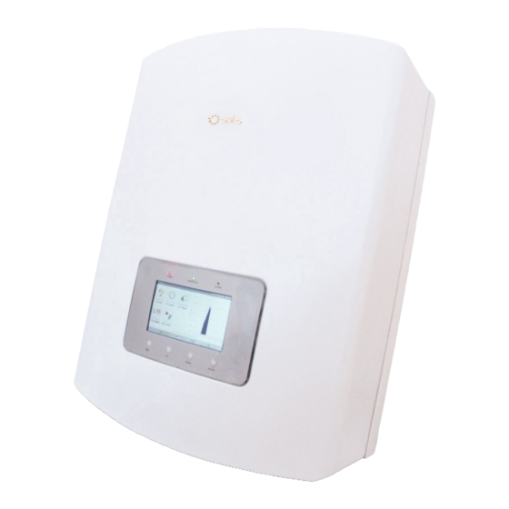
PV Grid Tie Inverter
Solis Three Phase Inverter
Installation and Operation Manual
Ginlong Technologies Co., Ltd.
No. 57 Jintong Road, Binhai Industrial Park, Xiangshan, Ningbo,
Zhejiang, 315712, P.R.China.
Tel: +86 (0)574 6578 1806
Fax: +86 (0)574 6578 1606
Please adhere to the actual products in case of any discrepancies in this user manual.
If you encounter any problem on the inverter, please find out the inverter S/N
Ginlong Technologies Co., Ltd
C
and contact us, we will try to respond to your question ASAP.
Ver 2.3
Advertisement
Table of Contents

Related Manuals for Ginlong Solis-20K


Summary of Contents for Ginlong Solis-20K
- Page 1 PV Grid Tie Inverter Solis Three Phase Inverter Installation and Operation Manual Ginlong Technologies Co., Ltd. No. 57 Jintong Road, Binhai Industrial Park, Xiangshan, Ningbo, Zhejiang, 315712, P.R.China. Tel: +86 (0)574 6578 1806 Fax: +86 (0)574 6578 1606 Please adhere to the actual products in case of any discrepancies in this user manual.
- Page 2 Ginlong Technologies accepts no liability for customers' failure to comply with the instructions for correct installation and will not be held responsible for upstream or downstream systems Ginlong's equipment has supplied.
-
Page 3: Table Of Contents
Content …………………………………………………………… 1. Introduction ………………………………………… 1.1 Product Description 1.2 Packaging List ………………………………………………… …………………………………………………… 2. Safety Instructions 2.1 Safety Symbols ………………………………………………… …………………………………… 2.2 General Safety Instruction ………………………………………………… 2.3 Notice For Use …………………………………………………………… 3. Overview ………………………… 3.1 Inverter Interface Instructions ………………………………… 3.2 LED Status Indicator Light 3.3 Keypad ………………………………………………………... -
Page 4: Introduction
……………………………………… 7.3.2 Set Address There are 10 models for Solis three phase inverter: ……………………………………… 7.3.3 HMI Update Solis-20K, Solis-25K, Solis-30K, Solis-33K, Solis-25K-HV Solis-30K-HV, Solis-36K-HV, Solis-40K-HV, Solis-15K-LV, Solis-20K-LV ………………… 7.4 Advanced Info - Technicians Only …………………………………… 7.4.1 Alarm Message 7.4.2 Running Message... -
Page 5: Packaging List
Installation and Operation Manual instructions, which if not correctly followed, could result in electric shock. CAUTION: CAUTION, HOT SURFACE symbol indicates safety instructions, which if not Ginlong Technologies Co., Ltd Ver 2.3 correctly followed, could result in burns. 2.2 General Safety Instructions WARNING: DC input and AC output must be electrically isolated before operation. -
Page 6: Notice For Use
Inverter. The recommended rated trip current of the solar panel's DC isolator switched on. To stop the inverter, the Grid Supply Main OCPD, Solis-20K should be 40A, Solis-15K-LV should be 50A, Solis-25K, Switch (AC) must be switched off before the solar panel's DC isolator switched off. -
Page 7: Keypad
4. Product handing and storage 3. Overview 4.1 Product handing 1. The red marks below indicate perforations used to form handles for carrying the carton POWER with the inverter. The inverter requires 2 people to lift and carry. OPERATION ALARM Table 3.1 Status indicator 3.3 Keypad There are four keys in the front panel of the Inverter(from left to right): ESC, UP, DOWN... -
Page 8: Product Storage
5. Installation 4. Installation 4.2 Product storage 5.1 Select a Location for the Inverter If the inverter is not to be installed immediately, storage instructions and environmental conditions are below: WARNING: Risk of fire Despite careful construction, electrical devices can cause fires. Use the original box to repackage the inverter, seal with adhesive tape with the Do not install the inverter in areas containing highly flammable materials or desiccant inside the box. -
Page 9: Mounting The Inverter
5. Installation 5. Installation A sun shade is recommended to minimise direct sun exposure where ambient 5.2 Mounting the Inverter temperature may exceed 40℃. The inverter can be mounted to the wall or metal strut of module. The mounting holes should be consistent with the size of the bracket or the dimensions shows below. -
Page 10: Electrical Connections
5. Installation 5. Installation 5. Use supplied screws to secure the bottom of the inverter to the mount bracket. Figure 5.4 Mount the bracket to the wall Figure 5.6 Secure the inverter 4. Lift up the inverter, and make the slot on the back bracket of inverter align to the 5.3 Electrical Connections lip on the mounting bracket. -
Page 11: Protective Ground Wire Connection(Pe)
5. Installation 5. Installation 5.3.1 Protective ground wire connection(PE) To effectively protect the inverter, two grounding methods must be performed. Connect the AC grounding cable (Please refer to section 5.3.3) Connect the external grounding terminal. To connect the grounding terminal on the heat sink, please follow the steps below: 1) Prepare the grounding cable: recommend to use the 16mm²... -
Page 12: Dc Side Connection
5. Installation 5. Installation 5.3.2 DC side connection 4. Insert the contact pin into the connector housing until it locks in place. Screw the cap A) Please make sure the polarity of the output voltage of PV array matches the nut onto the connector housing. -
Page 13: Ac Side Connection
5. Installation 5. Installation 5.3.3 AC side connection For all AC connections, 10- 35mm 105 ℃ cable is required to be used. Please make sure the resistance of cable is lower than 1.5 ohm. If the wire is longer than ①Winding the first ②Winding the second ③Please tie the end with... -
Page 14: Inverter Monitoring Connection
COM2 and COM3 are for RJ45 terminal, which is used for communicating connection between inverters as well as the wired data monitoring. Figure 5.22 is the internet monitoring solution. Please refer to related instructions of Ginlong communication products. Figure 5.24 RJ45 communication connection terminals .22. -
Page 15: Start And Stop
6. Start and Stop 5. Installation 2. Use the network wire stripper to strip the insulation layer off the communication cable. 6.1 Start the inverter Using the standard wire sequence referenced in TIA/EIA 568B, separate the wires in the cable. Use a network cable crimp tool to trim the wire. Flatten the wire in the order shown in Figure 5.25. -
Page 16: General Operation
7. General Operation 7. General Operation Press the Up or Down key to enter the inverter yearly, monthly energy detail screen. In the current interface, press the Enter key to move the cursor, press the Up or Down key to view yearly, monthly energy detail. Monthly Energy 2015-02-23 19 35 Pressing the ESC... -
Page 17: Information
7. General Operation 7. General Operation 7.2 Information 7.3 Settings The inverter LCD provides access to operational data and information. Select The following interface is displayed when the Settings menu is selected, press the "Information" sub menu, turn the page by scrolling up or down. UP/DOWN keys to select different option, press the ENTER key to enter the submenu. -
Page 18: Advanced Info - Technicians Only
7. General Operation 7. General Operation 7.3.2 Setting Address 7.4 Advanced Info - Technicians Only This function is used to set the address of an inverter connected to PC for communication NOTE: purposes. The address number can be assigned from “01” to “99” . Password required –... -
Page 19: Alarm Message
7. General Operation 7. General Operation 7.4.1 Alarm Message 7.4.3 Version The screen shows the hardware version and the software version of the inverter. The display shows the 10 latest alarm messages. Screens can be scrolled manually by pressing the UP/ DOWN keys. 版本号... -
Page 20: Daily Energy
7. General Operation 7. General Operation 7.4.7 Yearly Energy 7.4.5 Daily Energy The screen shows the inverter monthly energy detail of one year. The screen shows the daily energy detail of the inverter. Yearly Energy 2015-02-23 19 35 Daily Energy 2015-02-23 19 35 3 . -
Page 21: Advanced Settings - Technicians Only
7. General Operation 7. General Operation Select grid standard (Figure 7.22) 7.5 Advanced Settings - Technicians Only Select Standard 2015-02-23 19 35 NOTE: Select Standard To access to this area is for fully qualified and accredited technicians only. BRAZIL Please follow 7.4 to enter password to access this menu. Select Advanced Settings from the Main Menu to access the following options: Advanced Set. - Page 22 7. General Operation 7. General Operation Range for User-Def (15-20)K-LV User-Def 2015-02-23 19 35 OV-G-V1: 122---180V OV-G-F1: 50.2-53Hz(60.2-63Hz) OV-G-V1: 144V OV-G-V1-T: 1.0s OV-G-V2: 150V OV-G-V2-T: 0.2s OV-G-V1-T: 0.1---9s OV-G-F1-T: 0.1---9s UN-G-V1: 104V UN-G-V1-T: 1.0s OV-G-V2: 122---180V OV-G-F2: 51-53Hz(61-63Hz) UN-G-V2: UN-G-V2-T: 0.2s OV-G-V2-T: 0.1---1s OV-G-F2-T: 0.1---9s...
-
Page 23: Grid On/Off
7. General Operation 7. General Operation 7.5.2 Grid ON/OFF This function is applicable by maintenance personnel only, wrong operation This function is used to start or stop the generation of the inverter. will prevent the inverter from reaching maximum power. Grid ON/OFF 2015-02-23 19 35 7.5.4 Clear Energy... -
Page 24: Reset Password
7. General Operation 7. General Operation 7.5.7 Reset Password 7.5.9 Special Settings First enter the current password, Press the DOWN key to move the cursor, press the UP key to revise the password digit. This section is applicable to maintenance personnel only. Reset Password 2015-02-23 19 35 There are 4 items in special settings submenu. -
Page 25: External Epm Set
7. General Operation 8. Maintenance Solis three phase string inverter does not require any regular maintenance. However, cleaning the 7.5.11 External EPM set heat-sink will help in dissipating heat and increase the life time of inverter. The dirt on the This setting is for export power control. -
Page 26: Maintenance
8. Maintenance 9. Troubleshooting Alarms Cause Solution Alarms Cause Solution Test – DC switch OFF Test – DC switch OFF • Check frequency at the inverter test points • Check PV connections • If Frequency measures high, adjust upper • Input voltage low/missing •... - Page 27 9. Troubleshooting 9. Troubleshooting NOTE: If the inverter displays any alarm message as listed in Table 9.1; please turn Alarms Cause Solution off the inverter (refer to Section 6.2 to stop your inverter) and wait for 5 minutes Test – With DC Switch OFF before restarting it (refer to Section 5.1 to start your inverter).
-
Page 28: Specification
10. Specification 10. Specification Model Solis-20K Model Solis-25K Max. DC input voltage (Volts) Max. DC input voltage (Volts) 1000 1000 Rated DC voltage (Volts) Rated DC voltage (Volts) Start-up voltage (Volts) Start-up voltage (Volts) MPPT voltage range (Volts) MPPT voltage range (Volts) 200...800... - Page 29 10. Specification 10. Specification Model Solis-30K Model Solis-33K Max. DC input voltage (Volts) Max. DC input voltage (Volts) 1000 1000 Rated DC voltage (Volts) Rated DC voltage (Volts) Start-up voltage (Volts) Start-up voltage (Volts) MPPT voltage range (Volts) MPPT voltage range (Volts) 200...800 200...800 Max.
- Page 30 10. Specification 10. Specification Model Solis-25K-HV Model Solis-30K-HV Max. DC input voltage (Volts) Max. DC input voltage (Volts) 1000 1000 Rated DC voltage (Volts) Rated DC voltage (Volts) Start-up voltage (Volts) Start-up voltage (Volts) MPPT voltage range (Volts) MPPT voltage range (Volts) 200...800 200...800 Max.
- Page 31 10. Specification 10. Specification Model Solis-36K-HV Model Solis-40K-HV Max. DC input voltage (Volts) Max. DC input voltage (Volts) 1000 1000 Rated DC voltage (Volts) Rated DC voltage (Volts) Start-up voltage (Volts) Start-up voltage (Volts) MPPT voltage range (Volts) MPPT voltage range (Volts) 200...800 200...800 Max.
- Page 32 10. Specification 10. Specification Model Solis-15K-LV Model Solis-20K-LV Max. DC input voltage (Volts) Max. DC input voltage (Volts) 1000 1000 Rated DC voltage (Volts) Rated DC voltage (Volts) Start-up voltage (Volts) Start-up voltage (Volts) MPPT voltage range (Volts) MPPT voltage range (Volts) 200...800...
Need help?
Do you have a question about the Solis-20K and is the answer not in the manual?
Questions and answers