Advertisement
RTBSB - 201.xxx
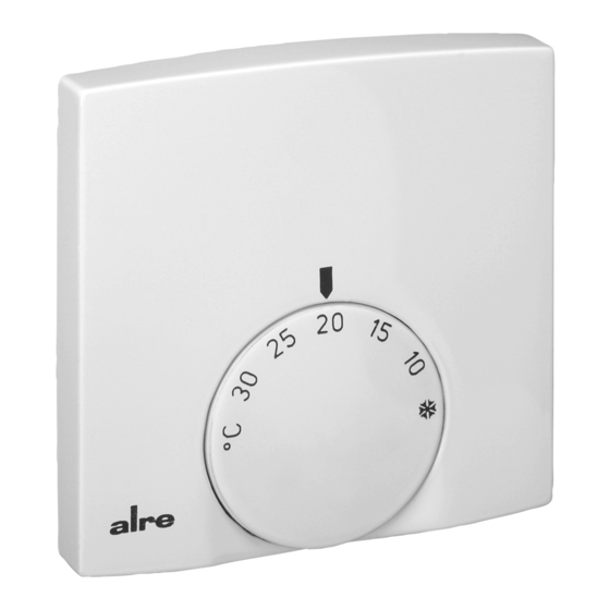
Raumtemperaturregler Bimetall / Bimetal room temperature controller
Régulateur bimetallique pour le réglage de la temperature ambiante
Sicherheitshinweis!
Dieses Gerät darf nur durch eine Elektrofachkraft geöffnet und gemäß dem entsprechenden
Schaltbild im Gehäusedeckel / auf dem Gehäuse / in der Bedienungsanleitung installiert wer-
den. Dabei sind die bestehenden Sicherheitsvorschriften zu beachten. Nach der Installation
ist der Betreiber, durch die ausführende Installationsfirma, in die Funktion und Bedienung der
Regelung einzuweisen. Die Bedienungsanleitung muss für Bedien- und Wartungspersonal an
frei zugänglicher Stelle aufbewahrt werden.
Entsorgungshinweis
Gerät nicht im Hausmüll entsorgen! Elektronische Geräte sind entsprechend der Richt-
linie über Elektro- und Elektronik - Altgeräte (WEEE - Richtlinie) über die örtlichen Sam-
melstellen für Elektronik - Altgeräte zu entsorgen.
1. Anwendung
Dieser Raumtemperaturregler wurde speziell für die Regelung oder Überwachung von Tempe-
raturen in Büros, Wohnräumen und Hotels entwickelt. Elektrische Fußbodenheizungen müssen
über einen zusätzlichen Leistungsschutz angesteuert werden. Hierbei ist darauf zu achten,
dass die Leistung der Heizung auch bei Dauerbetrieb den Estrich nicht überhitzen kann. Bei
Warmwasserheizungen sind maximal 10, bei Kühlung maximal 5 stromlos geschlossene Ven-
tile zu verwenden. Gegebenenfalls benötigte Temperaturbegrenzungen müssen zusätzlich ins-
talliert werden. Für andere, vom Hersteller nicht vorherzusehende Einsatzgebiete, sind die dort
gültigen Sicherheitsvorschriften zu beachten. Eignung hierfür siehe Punkt 8. Gewährleistung.
2. Funktionen
Der Raumtemperaturregler erfasst mit einem innenliegenden Bimetallfühler die Raumtempe-
ratur und regelt entsprechend dem eingestellten Sollwert. Die Reglertypen RTBSB - 201.023
und RTBSB - 201.062 verfügen über einen „EIN / AUS" - Schalter, der Typ RTBSB - 201.062
zusätzlich über eine rote Lampe „Heizen". Der RTBSB - 201.075 verfügt über einen Schalter
„Absenken / Tag / Uhrenbetrieb" und eine grüne Lampe „Absenkbetrieb". Der RTBSB - 201.065
wurde speziell für 2 - Rohr - Leitungssysteme entwickelt und verfügt für den gemeinsamen
Heiz - Kühlausgang über einen Heiz - Kühl - Umschalter. Durch eine thermische Rückführung
wird eine sehr genaue Schaltdifferenz erreicht. Bereichseinengung siehe Bild 2. Bei Beschalten
der Klemme
mit 230 V ~ wird auf eine um ca. 3 K geringere Temperatur geregelt (Nachtab-
senkung).
3. Montage / Anschluss
Auslieferungszustand offen. Montage wegen des geringen Verdrahtungsraumes auf eine
UP - Dose empfohlen, kann aber auch auf ebenen nichtleitfähigen Untergrund erfolgen. Öffnen
und Schließen wie in Bild 1 beschrieben. Die zur Wand zeigenden, verdeckten Lüftungsschlitze
dürfen nicht verschlossen werden, da dies zu einer fehlerhaften Regelung führt.
Achtung! Den Einstellknopf immer erst vor dem Abnehmen des Gehäusedeckels abziehen!
Der Einstellknopf darf nicht ohne vorheriges Aufsetzen des Gehäusedeckels aufgesteckt und
wieder abgezogen werden!
Achtung! Der Regler ist für übliche Verunreinigungen in Wohn- und Büroräumen geeignet. Un-
verhältnismäßiger Schmutz und Staub während der Installations- oder Renovierungsarbeiten
kann die Kontakte verschmutzen und zur Nichtfunktion des Reglers führen.
1. Knopf abnehmen /
Remove the knob / Enlever le bouton
2. Schraube entfernen /
Unscrew the screw / Dévisser la vis
3. Drücken /
Press / Presser
4. Ziehen /
Pull / Tirer
Bild 1 / Picture 1 / Illustration 1
4. Technische Daten
Fühlerelement / Kontakt:
Versorgungsspannung und
Schaltvermögen:
Regelbereich:
Schaltdifferenz:
Skala:
max. zulässige Temperatur-
änderungsgeschwindigkeit
der Regelstrecke:
Schutzart:
Schutzklasse:
Max. Luftfeuchtigkeit:
Bemessungsstoßspannung:
Verschmutzungsgrad:
Energieeffizienzklasse:
5. Verwendete Symbole
Symbol
Erklärung
L
Phase Versorgungs- und Schaltspannung
N
Neutralleiter Versorgung und Verbraucher
Ausgang Heizen
Ausgang Kühlen oder Kühlbetrieb oder Frostschutz (5 ° C)
Temperatur - Absenkbetrieb (ECO - Betrieb)
Temperatur - Absenkeingang (ECO - Eingang)
I
Ein
0
Aus
Stand 12.2017 (14 / 096)
Bimetall, Öffner oder Wechsler Typ 1 C
250 V ~, 2(1)A
5 ° C ... 30 ° C
ca. 0,5 K
° C Skala bzw. Skala * ... 6
(entspricht 5 ° C ... 30 ° C)
4 K / h
IP 30 nach entsprechender Montage
II nach entsprechender Montage
95 % rH, nicht kondensierend
4000 V
2
I (Beitrag zur jahreszeitbedingten
Raumheizungs - Energieeffizienz 1 %)
Safety information!
This bimetal room temperature controller is only to be opened by a qualified electrician and
installed in keeping with the wiring diagram on the housing cover / on the cover / and in the
operating instructions. In so doing, the safety regulations are to be noted. Following installation,
the company concerned is to instruct the operator in the function and operation of the control
system. The operating instructions are to be kept at a place that is easily accessible for both
operating and maintenance staff.
Disposal information
Do not dispose of this device through domestic waste! Electronic devices must be
disposed of in accordance with the Directive on Waste Electrical and Electronic Equip-
ment (WEEE directive) via the local collection points for waste electrical and electronic
equipment.
1. Application
This bimetal room temperature controller has been specially devised for the control and super-
vision of temperatures in offices, living spaces and hotels. Electric floor heating systems need
to be controlled by an additional power contactor. Care must be taken thereby to ensure that
the performance of the controlled system cannot, even if the system is operated continuously,
result in an overheating of the pavement. With hot water heating systems, no more than 10
normally closed valves must be used and no more than 5 with water cooling systems. Where
applicable, temperature limiters need to be installed in addition. Notice is to be taken of those
safety regulations applying to other fields of use not anticipated by the manufacturer. For suit-
ability in this respect see Item 8 Warranty.
2. Functional description
The room temperature controller described herein has been equipped with an internal bi-
metal sensor that captures the currently existing room temperature. The device controls the
related heating or cooling system in accordance with the adjusted set value. The controller
models RTBSB - 201.023 and RTBSB - 201.062 have been equipped with an ON / OFF switch,
while the controller model RTBSB - 201.062 disposes of an additional red „heating" lamp.
The RTBSB - 201.075 has been provided with a „temperature decrease mode / daytime op-
eration / clock - controlled operation" selector switch and with a green „temperature decrease
mode" lamp. The RTBSB - 201.065 has been specially devised for the control of 2 - pipe sys-
tems and equipped with a joint heating / cooling output, the control of which is effected by a
changeover switch. The thermal recirculation realised with the devices of this series enables
to attain a highly precise switching difference. Regarding the suppression of the setting range,
please see picture 2. The room temperature is decreased by approx. 3 K when connecting the
230 V ~ power supply to the terminal
3. Mounting / Installation
The controller is delivered in opened condition. As there is only little space available for its wir-
ing, it is recommended to install the device on an UP box. The controller can nevertheless be
mounted on a non - conductible surface. The opening and closing of the housing takes place as
described in picture 1. The venting slots that point to the wall must not be covered. If otherwise,
there is danger that the control operations performed by the device become incorrect.
Caution: Always make sure to pull off the knob only prior to removing the housing cover! The
adjusting knob must neither be put on, nor be pulled off without having put on the housing
cover beforehand!
Caution: The device is able to resist to the types of dirt or dust that normally occur in offices
and living spaces. Excessive volumes of dust and / or dirt produced during the installation or
during renovation works may soil the contacts and can lead to a breakdown of the device.
Einstellfahne für minimalen
Temperaturwert
Pin for the setting of the
minimum temperature value
Broche pour l'ajustage de la
valeur de température minimale
Bild 2 / Picture 2 / Illustration 2
4. Technical data
Sensing element / contact:
Supply voltage and switching
capacity:
Control range:
Switching difference:
Imprinting:
Max. admissible temperature
changing speed of the
controlled system:
Degree of protection:
Protection class:
Max. admissible air moisture:
Rated impulse voltage:
Degree of pollution:
Energy efficiency class:
5. Explanation of symbols
Symbol
Explanation
L
Supply and switching voltage (phase)
N
Supply and consumers (neutral conductor)
Heating output
Cooling or cooling mode or frost protection (5 ° C) mode output
Temperature decrease mode (ECO mode)
Temperature decrease mode (ECO input)
I
ON
0
OFF
1
(night temperature decrease).
Einstellfahne für maximalen
Temperaturwert
Pin for the setting of the
maximum temperature value
Broche pour l'ajustage de la
valeur de température maximale
bimetal sensor, type 1 C / open or break contact
250 V ~, 2(1) A
5 ° C ... 30 ° C
approx. 0.5 K
° C scale or scale * ... 6
(equivalent to 5 ° C ... 30 ° C)
4 K / h
IP 30 (after according installation)
II (after according installation)
95 % rh, non - condensing
4000 V
2
I (contribution to seasonal space heating
energy efficiency 1 %)
4 12 672 07
Advertisement
Table of Contents

Related Manuals for alre RTBSB-201 Series


Summary of Contents for alre RTBSB-201 Series
- Page 1 RTBSB - 201.xxx Raumtemperaturregler Bimetall / Bimetal room temperature controller Régulateur bimetallique pour le réglage de la temperature ambiante Sicherheitshinweis! Safety information! Dieses Gerät darf nur durch eine Elektrofachkraft geöffnet und gemäß dem entsprechenden This bimetal room temperature controller is only to be opened by a qualified electrician and Schaltbild im Gehäusedeckel / auf dem Gehäuse / in der Bedienungsanleitung installiert wer- installed in keeping with the wiring diagram on the housing cover / on the cover / and in the den.
- Page 2 DIN. Les caractéristiques techniques ne peuvent être garanties que dans cette mesure. La vérification du dispositif en rapport à sa qualification et appropriation pour l’application prévue ou son utilisation sous conditions de service incombe au client. Nous n’assumons aucune garantie à cet égard. Sous réserve de modifications techniques. ALRE - IT Regeltechnik GmbH Richard - Tauber - Damm 10 D - 12277 Berlin Tel.: + 49 (0) 30 / 399 84 - 0...
Need help?
Do you have a question about the RTBSB-201 Series and is the answer not in the manual?
Questions and answers