Advertisement
RTBSB-001.xxx
Thermostat électronique à bilame avec contact de permutation pour la régulation de la température ambiante
Sicherheitshinweis!
Dieses Gerät darf nur durch eine Elektrofachkraft geöffnet und gemäß dem entsprechenden Schaltbild im
Gehäusedeckel / auf dem Gehäuse / in der Bedienungsanleitung installiert werden. Dabei sind die beste-
henden Sicherheitsvorschriften zu beachten. Nach der Installation ist der Betreiber, durch die ausführende
Installationsfirma, in die Funktion und Bedienung der Regelung einzuweisen.
Die Bedienungsanleitung muss für Bedien- und Wartungspersonal an frei zugänglicher Stelle aufbewahrt
werden.
1. Anwendung
Dieser Raumtemperaturregler wurde speziell für die Regelung oder Überwachung von Temperaturen in
Büros, Wohnräumen und Hotels entwickelt und ist geeignet für alle Heizungsarten. Bei elektrischen Fuß-
bodenheizungen ist darauf zu achten, dass die Leistung der Heizung auch bei Dauerbetrieb den Estrich
nicht überhitzen kann. Bei Warmwasserheizungen sind auf den Heizausgang max. 10 stromlos geschlos-
sene, oder auf den Kühlausgang max. 5 stromlos offene Ventile anzuschließen. Im Kühlfall sind max. 5
stromlos geschlossenen Ventile auf den Kühlausgang oder max. 10 stromlos offene Ventile auf den Heiz-
ausgang anzuschließen.
Achtung! Bei dem Reglertyp RTBSB-001.065 speziell für 2-Rohr-Klimasysteme, ist die Bedruckung des
Heiz-/Kühl-Umschalters auf stromlos geschlossene Ventile ausgelegt. Die übrigen in dieser Anleitung be-
schriebenen Reglertypen sind speziell für 4-Rohr-Klimasysteme entwickelt. Gegebenenfalls benötigte
Temperaturbegrenzungen müssen zusätzlich installiert werden.
Für andere, vom Hersteller nicht vorherzusehende Einsatzgebiete, sind die dort gültigen Sicherheitsvor-
schriften zu beachten. Eignung hierfür siehe Punkt 9. Gewährleistung.
2. Funktionen
Der Raumtemperaturregler erfasst mit einem innenliegenden Bimetallfühler die Raumtemperatur und
regelt entsprechend dem eingestellten Sollwert. Die einzelnen Reglertypen unterscheiden sich durch die
Ausstattung, wie Schalter „Ein / Aus" und „Lüfterausgang" (.026), Schalter „Heizen / Kühlen" (.065), Schal-
ter „Absenken / Komfort / Automatik", (.075) Lampe grün „Absenkung" (.075).
Thermische Rückführung
Da während des Heiz- oder Kühlvorgangs der Regler die Raumtemperatur erst relativ spät erfasst, wird
mittels einer thermischen Rückführung der Regler rechtzeitig zum Ausschalten angeregt und so eine sehr
genaue Schaltdifferenz erreicht.
Bereichseinengung
Mittels der sich unter dem Knopf befindlichen Einstellfahnen kann der Einstellbereich mechanisch
begrenzt werden (vgl. Punkt 6.).
Nachtabsenkung
Bei Reglern mit Absenkbetrieb (Uhrensymbol im Anschluss-Schaltbild) wird bei Beschalten der
Klemme
mit 230 V~ die Raumtemperatur um ca. 4 K abgesenkt.
3. Montage/Anschluss
Der einfacheren Montage wegen wird der Regler geöffnet ausgeliefert. Die Montage auf eine Unterputz-
dose wird empfohlen, kann aber auch auf ebenen, nichtleitfähigem Untergrund erfolgen. Das Öffnen und
Schließen des Reglers erfolgt wie unter Punkt 6. dargestellt. Zunächst Knopf abnehmen, Häkchen mit
einem Schlitzschraubendreher leicht nach innen drücken und Reglerkappe nach unten aufklappen. Die
Lüftungsschlitze dürfen nicht verschlossen werden, da dies zu einer fehlerhaften Regelung führt.
Achtung! Der Regler ist für übliche Verunreinigungen in Wohn- und Büroräumen geeignet. Unverhältnis-
mäßiger Schmutz und Staub während der Installations- oder Renovierungsarbeiten kann die Kontakte ver-
schmutzen und zur Nichtfunktion des Reglers führen. In diesem Fall sind die Kontakte von einer Elektro-
fachkraft zu reinigen. Dies kann zum Beispiel durch Ausblasen oder durch reinigen mittels eines trockenen
Pinsels geschehen.
4. Technische Daten
Fühlerelement:
Versorgungsspannung und Schaltvermögen: siehe Punkt 7. Typenschild
Regelbereich:
Schaltdifferenz:
Skala:
max. zulässige Temperatur-
änderungsgeschwindigkeit der Regelstrecke: 4 K/h
Schutzart:
Schutzklasse:
Max. Luftfeuchtigkeit:
Gehäusematerial und -Farbe:
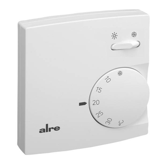
5. Klemmen- und Bediensymbole
Symbol
L
N
(als Klemmensymbol)
(als Bediensymbol)
I
O
Stand 03.2009 (EA 09/015) JD
Raumtemperaturregler Bimetall „Wechsler"
Bimetal room temperature controller with changeover contact
Bimetall „Wechsler", Typ 1C
5 ... 30°C
ca. 0,5 K
°C Skala
IP30
II nach entsprechender Montage
95%rH, nicht kondensierend
Kunststoff ABS, reinweiß (ähnlich RAL 9010)
Bedeutung
Phase Versorgungsspannung
Neutralleiter
Ausgang Heizen
Temperatur-Absenkeingang (ECO-Eingang)
Zusatzheizung
Ventilatorausgang
Ausgang Kühlen
Frostschutz ca. 5°C
Ein
Aus
Temperatur-Absenkbetrieb (ECO-Betrieb)
Temperatur-Wohlfühlpunkt
Safety information!
D
No persons other than expert electricians only must open this device in due compliance with the related
wiring diagram shown in the housing cover / on the housing / represented in the corresponding operating
instructions. All expert electricians committed to the execution of any such works must comply with the
relevant safety regulations currently operative and in force. The company charged with the installation of
the device must, after the completion of the installation works, instruct the user of the control system into
its functions and in how to operate it correctly.
These operating instructions must be kept at a place that can be accessed freely by the operating and/or
servicing personnel in charge.
1. Application
This bimetal room temperature controller has been specially devised for the control and super-
vision of temperatures in offices, living spaces and hotels. It serves for use with all types of heating
systems. With electric floor heating systems, care must be taken to ensure that the performance of the
controlled system cannot, even if the system is operated continuously, result in an overheating of the
pavement. With hot water heating systems, no more than 10 normally closed valves must be connected to
the cooling outlet and no more than 5 normally opened valves to the cooling outlet. If used for cooling pur-
poses, no more than 5 normally opened valves must be connected to the cooling outlet, while no more
than 10 normally closed valves must be connected to the heating outlet.
Caution: The imprint on the heating / cooling changeover switch installed on the controller model RTBSB-
001.065 (specially designed for use with two-pipe systems) relates to normally closed valves only. All other
controller models described herein have been devised for use with four-pipe climate systems. Where
applicable, temperature limiters need to be installed in addition.
Regarding other applications not to be foreseen by the manufacturer of this device, the safety standards
concerning these applications need to be followed and adhered to. Regarding the aptitude of the device
for any such other application, please refer to section 9 herein (Warranty).
2. Functional description
The room temperature controller described herein is equipped with an internal bimetal sensor that captures
the currently existing room temperature. The device controls the related heating or cooling system in accor-
dance with the adjusted set value. The individual controller models differ in their equipment, such as in an
ON/OFF switch and a fan outlet (.026), a "heating / cooling switch" (.065), a "temperature decrease mode /
comfort mode / automatic mode" selector switch (.073) or a green "temperature decrease mode active" indi-
cator lamp (.075).
Thermal recirculation
As, during the heating and/or cooling procedure, the controller usually captures the actually prevailing room
temperature at a rather late point, a thermal recirculation has been realised with the device that enables to
excite it early enough with the consequence that a very precise switching difference can be attained.
Range suppression
The mobile setting elements located underneath of the knob enable to delimit the setting range mechanically
(see section 6).
Night temperature decrease mode
With all controller models that enable to operate in night temperature decrease mode (indicated by the clock
symbol shown in the connection diagram), the room temperature is decreased by approx. 4K when connec-
ting the 230 V~ power supply to the terminal
3. Mounting / Installation
The controller is, in order to facilitate its installation, delivered in opened condition. It is recommended to
install the device on an UP box. The device can nevertheless be mounted on a non-conductible, plane and
solid surface. The opening and closing of the housing takes place as described in section 6. Remove the
turning knob first, then press the small hook inwards by means of a slot screwdriver and open the control-
ler cover by folding it down. The venting slots must not be covered. If otherwise, there is danger that the
control operations performed by the device become incorrect.
Caution: The device is able to resist to the types of dirt or dust that normally occur in offices and
living spaces. Excessive volumes of dust and/or dirt produced during the installation or during
renovation works may soil the contacts and can lead to a breakdown of the device. In any such
case, the contacts need to be cleaned by an expert electrician. This may for example be effected by
blowing the device down or by cleaning it with a dry brush.
4. Technical data
Sensing element:
Supply voltage and switching capacity:
Control range:
Switching difference:
Scale:
Max. admissible temperature
changing speed of the controlled system: 4 K/h
Degree of protection:
Protection class:
Max. admissible air moisture:
Housing material and colour:
5. Terminals and operating symbols
Symbol
L
N
(terminal symbol)
(operating symbol)
I
O
.
bimetal sensor, type 1C
see section 7, type plate
5 ... 30°C
approx. 0.5 K
in °C
IP30
II (after according installation)
95% r.h., non condensing
plastic (ABS), pure white (similar to RAL 9010)
Explanation
Supply voltage phase
Neutral conductor
Heating output
Temperature decrease input (ECO input)
Additional heating
Fan output
Cooling output
Fros protection (approx 5°C)
ON
OFF
Temperature decrease mode (ECO mode)
Thermal well-being point
GB
4 12 692 02
Advertisement
Table of Contents

Subscribe to Our Youtube Channel
Related Manuals for alre RTBSB-001 Series


Summary of Contents for alre RTBSB-001 Series
- Page 1 RTBSB-001.xxx Raumtemperaturregler Bimetall „Wechsler“ Bimetal room temperature controller with changeover contact Thermostat électronique à bilame avec contact de permutation pour la régulation de la température ambiante Sicherheitshinweis! Safety information! Dieses Gerät darf nur durch eine Elektrofachkraft geöffnet und gemäß dem entsprechenden Schaltbild im No persons other than expert electricians only must open this device in due compliance with the related Gehäusedeckel / auf dem Gehäuse / in der Bedienungsanleitung installiert werden.
- Page 2 Il controllo del dispositivo in relazione all’idoneità per lo scopo di destinazione previsto dal committente e all’impiego in condizioni di servizio è a carico del cliente. Non assumiamo alcuna garan- zia al riguardo. Salvo modifiche di ordine tecnico. ALRE-IT Regeltechnik GmbH · Richard-Tauber-Damm 10 · D-12277 Berlin Tel.: +49(0)30/ 399 84-0 · Fax: +49(0)30/ 391 70 05 · mail@alre.de · www.alre.de...
Need help?
Do you have a question about the RTBSB-001 Series and is the answer not in the manual?
Questions and answers