Advertisement
-GW,
RCON-GW-TRE
EC Gateway Unit, EC Connection Unit,
REC Terminal Unit
First Step Guide First Edition
Thank you for purchasing our product.
Make sure to read the Safety Guide and detailed Instruction Manual (DVD) included with the
product in addition to this First Step Guide to ensure correct use.
This Instruction Manual is original.
Warning: Operation of this equipment requires detailed installation and operation instructions
which are provided on the DVD Manual included in the box this device was
packaged in. It should be retained with this device at all times.
A copy of the DVD Manual can be requested by contacting your nearest IAI Sales
Office listed at the back cover of the Instruction Manual or on the First Step Guide.
• Using or copying all or part of this Instruction Manual without permission is prohibited.
• The company names, names of products and trademarks of each company shown in the sentences
are registered trademarks.
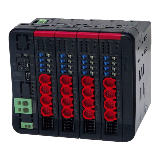
REC system is constructed with EC Gateway Unit (REC-GW), EC Connection Unit (RCON-EC) and REC
Terminal Unit (RCON-GW-TRE) that are explained in this manual.
EC Gateway Unit is a communication unit to be connected to the field network and must be located on the
most left side of the REC system.
EC Connection Unit is a unit to be connected to the ELECYLINDER and must be located on the right side
of the EC Gateway Unit.
The REC Terminal Unit is a terminal resistor that should be allocated at the most right end of REC system.
Product Check
This product is comprised of the following parts if it is of standard configuration.
If you find any fault in the contained model or any missing parts, contact us or our distributor.
1. Parts
(1) EC Gateway Unit (REC-GW)
No.
Part Name
Model
Number
Refer to "How to read the model
1 EC Gateway Unit
1
plate", "How to read the model code"
Accessories
REC Terminal Unit
2
RCON-GW-TRE
1
(Terminal Resistance)
MSTB2.5/5-STF-5.08 AU
(Manufactured by
CC-Link Connector
PHOENIX CONTACT)
3
(Enclosed for CC-Link
1
Connection Type)
MSTB2.5/5-STF-5.08 AU M
(Manufactured by
DeviceNet Connector
PHOENIX CONTACT)
4
(Enclosed for DeviceNet
1
Connection Type)
5 First Step Guide
ME0395
1
6 Instruction Manual (DVD)
1
7 Safety Guide
M0194
1
1B
(2) EC Connection Unit (RCON-EC)
No.
Part Name
1 EC Connection Unit
Accessories
-EC
Drive Source Cutoff
2
Connector
3 First Step Guide
4 Safety Guide
2. Teaching Tool (Please purchase separately)
A teaching tool such as PC software is necessary when performing the setup for position setting, parameter
setting, etc. that can only be done on the teaching tool. Please prepare either of the following teaching tools.
No.
1
PC Software (Includes USB Exchange Adapter + USB Cable + Peripheral Communication Cable)
2
Touch Panel Teaching Pendant TB-02 (Standard/ Dead Man's Switch Mounted)
3
Touch Panel Teaching Pendant TB-03
3. Instruction manuals related to this product, which are contained in the instruction manual (DVD).
No.
1
REC Instruction Manual
2
PC Software RCM-101-MW/RCM-101-USB Instruction Manual
Touch Panel Teaching Pendant TB-02 Applicable for Position Controller
3
Instruction Manual
Touch Panel Teaching Pendant TB-03 Wired Link Applicable for Position
4
Controller Instruction Manual
4. How to read the model plate (This design is what is after UL/CE acquired.)
(1) EC Gateway Unit
Model Plate (Large)
Refer to "External Dimensions"
for the attached position.
REC Terminal Unit
Model
Serial Number
Caution Mark
(2) EC Connection Unit
Model Plate (Large)
Refer to "External Dimensions"
for the attached position.
Model
Serial Number
EC Connection Unit
Caution Mark
Mark
Use IAI specified cables only.
5. How to read the model code
(1) EC Gateway Unit
Remarks
R E C - G W - C C - T R N - * *
< Series >
< Type >
GW
: Gateway Unit
Select-TRN (with no terminal
unit) in the option if it is not
< I/OType >
necessary
CC : CC-Link Connection Type
DV : DeviceNet Connection Type
EP : EtherNet/IP Connection Type
Terminal Resistance (130Ω/110Ω)
PRT : PROFINET IO Connection Type
enclosed one unit each
Recommended Cable:
(2) EC Connection Unit
Dedicated cable for CC-Link
R C O N - E C - 4
< Series >
Recommended Cable:
< Type >
Dedicated cable for DeviceNet
EC : ELECYLINDER
(3) ELECYLINDER
* ELECYLINDER available for connection to REC System is only Option: ACR.
This Manual
E C -
-
< Series > < Type >
Model
Number
Remarks
Refer to "How to read the model
1
4 axis type
plate", "How to read the model code"
Recommended
Cable Size
0.5 to 1.25mm
2
DFMC1.5/4-ST-3.5
1
(AWG20 to 16, Copper Wire)
(Manufactured by PHOENIX CONTACT)
* Use cables with their rated
temperature on the isolation
sheath at 60°C or higher
ME0395
1
This Manual
M0194
1
Part Name
RCM-101-USB
TB-02/TB-02D
Name
Manual No.
ME0394
ME0155
ME0355
ME0376
Model Plate (small)
It is attached on the
bottom of the panel
front face.
Model Code (Partially)
Serial Number
Model Plate (small)
It is attached on the
bottom of the panel
front face.
Model Code (Partially)
Serial Number
Explanation of Mark
< Identification for IAI use only >
* There is no identification in
some cases
< Option >
TRN : With No Terminal Unit
CIE : CC-Link IE Field Connection Type
EC : EtherCAT Connection Type
PR : PROFIBUS-DP Type
< Number of Axes >
4 : 4 axis type
* only 4 axis type
-
-
-
- A C R
(
)
< Read >
< Stroke >
< Cable length >
< Option >
ACR : RCON-EC Connection Type
Basic Specifications
1. Specifications of Power Supply
Item
Power Input Voltage Range
24V DC ±10%
Supply Current
Described in "Current Amperage"
Power Supply Frequency Range
-
Current Amperage
Described in "Current Amperage"
In-Rush Current
Described in "Current Amperage"
Instantaneous Power Outage Endurance By 24V power supply
Protection Function against Electric Shock Class Ⅲ
2. Specifications of Control Part
Item
Number of Controlled Axes
1 to 16 axes
Data Memory System
FRAM 256kbit
SIO Interface (T. P. Connector)
Communication System: RS485, Baud Rate: 9.6/19.2/38.4/57.6/115.2/230.4kbps
SIO Interface (USB Connector)
Communication System: USB, Baud Rate: 12Mbps
Model
PIO Interface
None
Conformed Extension I/O Interface
CC-Link, CC-Link IE Field, DeviceNet, EtherCAT, EtherNet/IP, PROFIBUS-DP,
(Field Network Interface)
PROFINET IO
TB-03
Pulse Train Type
Unavailable to Control
Brake Output Voltage
24V DC ±10%
Calendar Feature
None
Applied Safety Category
-
Driver Source Cutoff System
Drive source cutoff with semiconductor (Power MOSFET)
Stop Input
Break Contact Input
Stop Action
Turning servo OFF + Drive source cutoff
Enable Input
None
T. P. Enable Input
Available
Enable Action
Turning servo OFF
Protective functions
Overcurrent, temperature error, encoder line breakage and overload
Preventive / Predictive Maintenance Feature
None
LED Display
Refer to section in "Troubleshooting (LED Display)"
Brake Compulsory Release Feature
Brake release switch equipped on EC Connection Unit
Jog
Jog switch equipped on EC Connection Unit
Oversea Certifications
Planned to acquire CE and UL
3. Environmental Specifications
Item
Environment of Use
Pollution Degree 2
Surrounding Air Temperature
0 to 55°C
Surrounding Humidity
85% RH or less (non-condensing)
Peripheral Ambience of Use
Refer to "Installation Environment"
Surrounding Storage Temperature
-20 to 70°C
Frequency 10 to 57Hz/Swing width: 0.075mm
Frequency 57 to 150Hz/Acceleration: 9.8m/s
Vibration Durability
XYZ Each direction Sweep time: 10min. Number of sweep: 10times
Protection Class
IP20
Altitude
1000m
Cooling Method
Natural air-cooling
Dielectric Withstanding Voltage
Between power supply terminal and FG 500V DC 10MΩ or more
Names for Each Part
(1) EC Gateway Unit
AUTO/MANU Switch
T.P.(SIO) Connector
USB Connector
24V Power
Supply Connector
Connector for
FG Connection
Front
Specification
Specification
Specification
2
T RUN LED
Field Network Connector
SYS LED
STOP LED
MODE LED
C ERR LED
STATUS 0 LED
STATUS 1 LED
Top
Advertisement
Table of Contents

Related Manuals for IAI REC-GW


Summary of Contents for IAI REC-GW
- Page 1 Controller Instruction Manual T. P. Enable Input Available REC system is constructed with EC Gateway Unit (REC-GW), EC Connection Unit (RCON-EC) and REC Enable Action Turning servo OFF 4. How to read the model plate (This design is what is after UL/CE acquired.) Terminal Unit (RCON-GW-TRE) that are explained in this manual.
-
Page 2: External Dimensions
(2) EC Connection Unit 4. Linking Units 4. Cooling Factors and Installation Item Specification Follow the specifications and dimensions shown below when you design and build a control board. External Dimensions (42.6 + 22.6 × N) W × 115H × 95D [mm] N: Total number of EC Connection Units T RUN LED Item Specification... - Page 3 Note When the operation pattern is to have all the axes operate acceleration and deceleration only and the operation 2. CC-Link IE Field (REC-GW-CIE) Note 1 duty is 100%, it is necessary that the calculation is done with the maximum current for the motor power supply.
-
Page 4: Starting Procedures
5. EtherNet/IP (REC-GW-EP) Forward When using this product for the first time, make sure to avoid mistakes and incorrect wiring by referring to Stop 7. PROFINET IO (REC-GW-PRT) the procedure below. Illuminating Alarm being generated In this section, explains how to start up especially for REC system. Follow an instruction manual (DVD) for Refer to the instruction manuals for each field network master unit for the details. - Page 5 2. CC-Link IE Field (REC-GW-CIE) 6. PROFIBUS-DP (REC-GW-PR) Panel Panel Name Color Status Explanation Name Color Status Explanation Display Display Illuminating Initialization completed Illuminating Operation in normal conditions Initialization completed, there is a diagnosis Hardware error occurred Flashing event STATUS 0...
Need help?
Do you have a question about the REC-GW and is the answer not in the manual?
Questions and answers