Table of Contents
Advertisement
Advertisement
Table of Contents
Troubleshooting

Subscribe to Our Youtube Channel
Related Manuals for IAI RCM-GW-CC


Summary of Contents for IAI RCM-GW-CC
- Page 1 CC-Link RCM-GW-CC Gateway Unit Operation Manual First Edition IAI America Inc.
-
Page 2: Table Of Contents
Table of Contents Outline······················································································································································· 1 1.1 CC-Link gateway unit··························································································································· 1 1.2 What is CC-Link··································································································································· 2 1.3 Application example of gateway unit···································································································· 3 1.4 Features ·············································································································································· 4 1.5 How to identify model ·························································································································· 6 Specifications and name of each part ······································································································· 7 2.1 General specifications ·························································································································... - Page 3 System build-up ······································································································································ 90 8.1. Communication setting for controller ································································································· 90 8.2. CC-Link communication setting ········································································································· 91 8.3. Master PLC address assignment······································································································· 93 8.4. CSP file·············································································································································· 97 CC-Link operation case ·························································································································· 98 9.1 Outline of configuration······················································································································ 98 9.2 Actuator operating pattern ················································································································· 99 9.3 Various settings on SIO link side ·······································································································...
-
Page 5: Outline
Outline 1.1 CC-Link gateway unit CC-Link Gateway Unit (hereinafter, referred to as CC-Link gateway or gateway unit) is a unit to connect the network of CC-Link communication protocol for an upper programmable controller (hereinafter, referred to as PLC) and SIO communication network (Modbus communication protocol) for a controller (for robo-cylinder) which is a sub-network. -
Page 6: What Is Cc-Link
1.2 What is CC-Link System of FA communication For FA communication, communication specifications depend on equipment on the communicating end, content of information and its purpose, however, are roughly divided into information level, controller level and field level as shown in the following diagram. Primary open network FA computer Device level... -
Page 7: Application Example Of Gateway Unit
CC-Link CC-Link has become wide spread mainly for FA as an open network for device level. Communication specifications are open to the public, therefore, equipment in compliance with CC-Link can be communicated without a program regardless of manufacturer. Presently, CC-Link is spread and operated by CC-Link association (CLPA: CC-Link Partner Association), which is a non-profitable organization. -
Page 8: Features
1.4 Features For CC-Link gateway, operation modes of the following four patterns can be selected. Position data limit designation mode Only position data can be directly designated, and the maximum connecting axis number totals 14 axes. Further, various status signals can be input and output, and present position data can be read. Speed, acceleration and deceleration can be set for parameters for each axis as fixed values. - Page 9 Operation mode and primary functions Positioning data designated Simple direct Position data Position No. mode value/Position Primary functions limit designated designated Normal Push No. designated mode mode positioning operation mode mode mode Position data ○ × ○ ○ ○ designated operation Speed, acceleration ×...
-
Page 10: How To Identify Model
1.5 How to identify model RCM-GW-CC Basic model For CC-Link Gateway unit... -
Page 11: Specifications And Name Of Each Part
Specifications and name of each part 2.1 General specifications Item Specification Power supply 24V DC ±10% Consuming current 300mA max. Communications standard CC-Link Ver1.10 (*1) Communications speed 10M/5M/2.5M/625k/156kbps (Selection with rotary switch) Communications system Broadcast polling system Synchronization system Frame synchronization system Encoding system NRZI Transmission path format... -
Page 12: External Dimension Drawing
2.2 External dimension drawing... -
Page 13: Name And Function Of Each Part
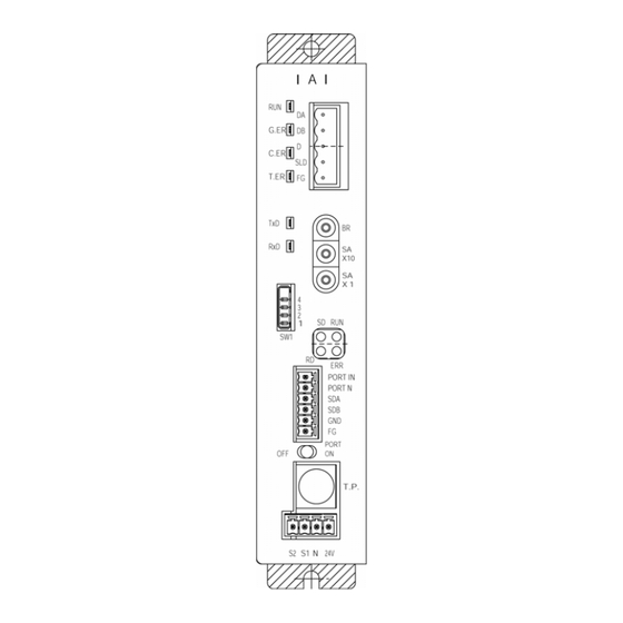
2.3 Name and function of each part [1] Gateway status [6] CC-Link communication indication LED connector RUN: Normal Communication line G.ER: Error Communication line C.ER: CC-Link error Ground T.ER: SIO link error SLD: Shield Earth [2] SIO communication status LED [7] CC-Link setting switch Baud rate TxD:... - Page 14 [1] Gateway status indication LED Indicating status Description Lit in green Indicates that the CPU of the gateway is operating. Unlit Indicates CPU operation stop status, and indicates that there is an error in the CPU of the gateway when this is not lit even if power is turned on. G.ER Lit in red Gateway CPU is in error, major fault stop status.
- Page 15 [3] Mode setting switch This switch sets the operation mode of the CC-Link gateway. Turn off the power for the CC-Link gateway to operate this switch. When selecting No.1, No.3 and No.4, setting of the position table for the controller is disabled. Input and output byte Description number...
- Page 16 [7] CC-Link setting switch Switch Description [Baud rate setting switch] This switch sets the communication rate. Setting of 5 or higher is prohibited. [Station No. setting switch] This switch sets with decimal two digits, however, effective setting is from 1 to 64. Positions of SA ×...
- Page 17 [9] Port switch This is a switch to enable the connector (T.P.) for teaching box and personal computer (PORT ON=Communication start). When connecting and disconnecting the teaching box and the communication cable connector for personal computer supporting software, turn OFF this switch. When using this switch, turn ON after connecting the connector.
-
Page 18: Installation And Noise Elimination
Installation and Noise Elimination Pay sufficient attention to the installation environment. 3.1 Installation Environment a. Since the gateway unit is not dust-proof or waterproof (oil proof), avoid using the gateway unit in a place subject to significant dust, oil mist or splashes of cutting oil. b. - Page 19 b. Precautions regarding wiring method Separate the communication lines for the gateway unit and the wiring for the CC-Link communication line from high-power lines such as a cable connecting to a power circuit. (Do not bundle together wiring for the communication lines with high-power lines or place them in the same cable duct.) c.
-
Page 20: Installation
3.4 Installation Design the control box size, installing position of the gateway unit and cooling method of the control box in such a way that the temperature around the gateway unit will not exceed 40°C. Install the gateway unit vertically on a wall, as shown below, and provide a minimum clearance of 50mm above and below the gateway unit and a minimum clearance of 100mm on the front for wiring. -
Page 21: Wiring
Wiring 4.1 Overall Configuration The following diagram shows an example of configuration to build a CC-Link by using a gateway unit. - Page 22 SIO communication connection is allowed even by multi-drop method using terminal blocks as follows. Gateway unit Terminal block Terminal resistor...
- Page 23 Reference Outline of CC-Link network configuration For details of the CC-Link, refer to the Operation Manual for the master side (PLC). This section describes a point for network wiring. The following diagram shows an example of network connection. Master station Slave station Slave station (Blue)
-
Page 24: Input And Output Signal Of Gateway Unit
4.2 Input and output signal of gateway unit Connection diagram Gateway unit (Blue) (White) CC-Link cable (Yellow) (Not colored) Connector for teaching box and personal computer Teaching box Port switch Teaching box Emergency stop signal output Allowable load voltage: 30V DC Allowable load current: 1A Gateway power supply 24V DC±10%... - Page 25 Port control and emergency stop signal output The connector port for the teaching box and personal computer can be also turned ON/OFF by an external signal other than the ON/OFF signal from the port switch on the gateway unit main body. Further, since the contact signal from the emergency stop pushbutton switch on the teaching box is outputted to the outside while the port is ON, this signal can be incorporated into the emergency stop circuit for the whole system.
- Page 26 Specification of input and output signal and wiring material...
-
Page 27: Building Of Sio Communication Network (Sio Communication)
4.3 Building of SIO communication network (SIO communication) 4.3.1 Wiring Basic Item Contents Number of connecting units 16 axes max. (Depends on the operation mode. Refer to “1.4 Features”) Communication cable length Total cable length 100m or shorter Communication cable Two-paired twisted pair shielded cable Terminal resistor Recommended cable: Taiyo Electric Wire &... - Page 28 Detail Connection Diagram The diagram below shows the details of the SIO communication connection. The controller link cables are optionally prepared, but the communication main line must be prepared by the customer. Gateway unit communication Two-paired shielded cable main line Recommended brand: Taiyo Electric Wire &...
- Page 29 Controller Link Cable (CB-RCB-CTL002) * Controller’s option Controller end E-Con connector 3-1473562-4 (Housing color: Orange) Mini DIN connector Signal Signal Yellow Orange Blue EMGA +24V EMGB The following parts are provided together: [1] Four-way junction Model: 5-1473574-4, Manufacturer: MP, Quantity: 1 [2] E-Con connector Model: 4-1473562-4, Manufacturer: MP, Quantity: 1 Compatible wire coating outline: 1.35-1.6mm...
- Page 30 Link connection for ERC2-SE SIO communication main line Gateway unit First axis (Incorporating terminal resistor) Second axis axis Terminal resistor e-CON connector (AMP made 4-1473562-4: Green) e-CON connector (AMP made 3-1473562-4: Orange) Junction (AMP made 3-1473574-4:) Recommended brand: Taiyo Electric Wire & Cable...
- Page 31 Detail connection diagram Connection between the gateway unit and four-way junction is the same as in item (2). Connection between each ERC2-SE and four-way junction is as shown in the following diagram. For details, refer to the Operation Manual for the ERC2-controller. Orange Blue Green...
- Page 32 Wiring of emergency stop (EMG) circuit When incorporating an emergency stop switch on the teaching box connected to the gateway unit into an emergency stop circuit, emergency stop signal output outputted from the “S1” and “S2” terminals for the gateway unit can be used. The controller for all of the connected robo-cylinders can be put into an emergency stop status by the emergency stop switch on the teaching box connected to the gateway unit.
- Page 33 Example of drive signal shutdown Gateway unit Teaching box EMG push T.P. connector button EMG reset push switch PCON-SE controller button SIO connector communication Connection connector detecting Gateway connection signal (H) power supply detecting circuit EMG signal detection Input power supply Power supply terminal block 24V DC (2A max/one unit)
- Page 34 Example of motor drive power shutdown Gateway unit Teaching box EMG push T.P. connector button EMG reset push switch PCON-SE controller button SIO connector communication Connection connector detecting Gateway connection signal (H) power supply detecting circuit EMG signal detection Input power supply Power supply terminal block 24V DC (2A max/one unit)
- Page 35 4.3.2 Setting of axis No. For PCON-SE, ACON-SE and ERC2-SE Set axis No. for slave station No. on the SIO link. Set the axis No. in a hexadecimal of 0 to F so that the first axis No. is 0, and 16 axis No.
-
Page 36: Outline Of Cc-Link
Outline of CC-Link 5.1 Data communication A scheme for basic data communication of the CC-Link is as shown in the following diagram. For slave to master station of the PLC, there are remote I/O stations which handle bit information only and remote device stations which handle bit information and word information (numeric data). -
Page 37: Address Assignment Of Master Plc
* CPU internal user device for PLC Input: Bit device Output: Internal relay: M Data register: D Word device Link register: 5.2 Address assignment of master PLC Number of maximum link points per one system is respectively 2048 points for remote input and output (RX, RY) and 256 points for remote register (RWw, RWr), and a buffer memory for this size is available. - Page 38 CC-Link memory map (MITSUBISHI Q series) I/O station PLC-CPU Master station buffer memory Remote station Device station Internal device Remote input (RX) (2 words) for one station Automatic Remote input refresh Bit data Remote output (RY) (2 words) for one station Automatic Remote output refresh...
-
Page 39: Address Configuration Of Gateway
Address configuration of gateway As described in 1.4 Features of gateway unit, actuators can be roughly operated by five modes. Address configuration as a slave depends on each mode. 6.1 Gateway control signal This is a signal to control the gateway, and consists of respective two words of word register for input and output. - Page 40 Details of input and output signal Signal Signal type Contents name Link communication starts at ON, and stops at OFF. When all of CFG15 to 0 (link connection axis selection) are OFF, do not turn ON MON signal. Further, while MON signal is ON, do not turn OFF all of CFG15 to 0. When all of CFG15 to 0 are OFF and MON signal is ON, the gateway unit becomes SIO link error, and the LED (T.ER) on the front of the unit is lit.
- Page 41 Signal Signal type Contents name Gateway unit now normally This is turned ON while operating output gateway unit is normally operating. This is synchronized with light up of the LED (RUN) on the front of the unit. Gateway unit error detection output This is turned ON when major fault stop status is detected.
-
Page 42: Position Data Limit Designation Mode
6.2 Position data limit designation mode This is an operation mode in which function of the controller is limited only to positioning, and allows for control of a maximum 14 axes. Position data for positioning is directly written in the data register of the PLC, and operation is performed. Communication for setting of speed, acceleration and deceleration cannot be performed. - Page 43 Address configuration In this mode, gateway control signal/status signal consists of two words respectively for input and output word register (RWr, RWw), and control signal/status signal for each axis consists of one byte respectively for input and output bit register (RX, RY) and one word for input and output word register (RWr, RWw). Numeric values in parentheses represent axis Nos.
- Page 44 Assignment for each axis Input and output signal for each signal consists of one byte respectively for input and output bit register (RX, RY) and one word for input and output word register (RWr, RWw). Control signal and status signal are ON/OFF signals in bit units. Position data designation and present position data are integers with a sign of one word (16 bits), and the PLC can handle numeric values of –32,768 to +32,767 (unit=1/100mm), however, set the position data in a range (0 to effective stroke length) of soft stroke for its actuator.
- Page 45 Details of input and output signal Signal Signal type Contents Detail name Cannot be used. Cannot be used. Cannot be used. Control Servo on command signal Pause command HOME Home return command CSTR Start command Reset command 16 bit integer with sign (unit: 0.01mm) Set position data in hexadecimal number.
-
Page 46: Position No. Designation Mode
6.3 Position No. designation mode This is an operation mode to operate by designating position No. of the position table, and allows for control of a maximum 14 axes. It is necessary to set the position table for each axis by personal computer supporting software or teaching box. - Page 47 Address configuration In this mode, the input and output signal for gateway control signals consist of two words respectively, and control signals for each axis consist of one byte respectively for input and output bit register and one byte respectively in input and output word register. Numeric values in the parentheses represent axis Nos.
- Page 48 Assignment for each axis Input and output signal for each axis consists of one byte respectively for input and output bit register and one byte respectively for input and output word register. Control signal and status signal are ON/OFF signals in bit units. Command position No.
- Page 49 Details of input and output signal Signal Signal type Application Contents Detail name Cannot be used. Cannot be used. Cannot be used. Position Servo on command data Pause command designation HOME Home return command CSTR Start command Reset command Set command position No. in hexadecimal number.
- Page 50 [List of alarm content] This list shows alarm content to be outputted (binary code) in PM8 to PM1 while an alarm occurring. For details of alarm content, refer to the Operation Manual for the controller. ○: ON ×: OFF Output Contents Remarks code...
-
Page 51: Position/Speed/Acceleration And Deceleration Designation
6.4 Position/speed/acceleration and deceleration designation This is an operation mode to perform operation by directly writing position data, acceleration and deceleration and speed in the register of the PLC, and allows for control of a maximum seven axes. Further, it is always possible to read present position data. Setting of position table for each axis is unnecessary. - Page 52 Address configuration In this mode, input and output for gateway control signal consist of two words respectively, and control signal for each signal consists of one word respectively for input and output bit register and two words respectively for input and output word register. Numeric values in the parentheses represent axis Nos.
- Page 53 Assignment for every axis Control signal and status signal are set by ON/OFF signal in bit units, and acceleration and deceleration are set by binary data of one byte (8 bits). Further, speed, position data designation and present position data can be handled in binary data of one word (16 bits), and the PLC can handle numeric values of –32,768 to +32,767.
- Page 54 Details of input and output signal Signal Signal type Contents Detail name Set acceleration and deceleration in hexadecimal number. (Unit: 0.01G) Example) When setting to 0.2G, designate 14H Acceleration (RynC and RynA are ON). 8 bit (decimal 200) at maximum 2G. deceleration data designation...
- Page 55 Signal Signal type Contents Detail name EMGS On emergency stop Cannot be used. Controller preparation completion Operation preparation completion (Servo on Status signal status) MOVE On moving HEND Home return completion PEND Positioning completion Alarm occurring 16 bit integer with sign (Unit: 0.01mm) Set position data in hexadecimal number.
-
Page 56: Push Operation Enable Mode
6.5 Push operation enable mode This is an operation mode to perform operation by directly writing current limit value (%) and positioning width for push in addition to direct designation of position data, acceleration and deceleration and speed into the register of the PLC, and allows for control of a maximum 3 axes. - Page 57 Address configuration In this mode, input and output for gateway control signal consist of two words respectively, and control signal for each axis consists of six words respectively for input register and three words respectively for output register. Further, axis No.0 uses bit register, and axis No.1 and 2 use word register. Numeric values in the parentheses represent axis Nos.
- Page 58 Assignment for each axis Control signal and status signal are set by ON/OFF signal in bit units, and acceleration and deceleration are set by binary data of one byte (8 bits). Designations of speed, position and positioning width and present position data handle numeric values in binary data of 1.5 words (24 bits). It is recommended to use control signal and status signal on bit register by performing transmission processing.
- Page 59 PLC input 1 word = 16 bits Position data designation Present position data Cannot be used Present position data (integer with sign) CAUTION 1. 24 bit binary data with a sign of PLC output and input is handled as a negative number when the uppermost bit is “1.”...
- Page 60 Details of input and output signal Signal Signal type Application Contents Detail name 24 bit integer with sign (unit: 0.01mm) Set position data in hexadecimal number of 24 bits. Example) In the case of +25.4mm, designate 0009EC (decimal 2540). Position data 24bit data (Note) designation...
- Page 61 Signal Signal type Application Contents Detail name 24 bit integer (Unit: 0.01mm) Set it in hexadecimal number. Example) In the case of +25.4mm, designate it as 0009EC (decimal 2540). Positioning ● Set position data in a range of soft stroke. width 24 bit data designation...
-
Page 62: Simple Direct Value/Position No. Designation Mode
6.6 Simple direct value/Position No. designation mode This is an operation mode for operation by mixing a mode to operate by designating position No. and a simple direct value mode in which target position data is designated by numeric value and the other movement parameters are designated by position No. - Page 63 6.6.1 Overall address configuration Input and output for gateway control signal are two words respectively, and only in this mode, patterns of position No. designated axes and number of axes are set by PPS0 to PPS2 and NPS0 to NPS4 of control word 0.
- Page 64 PLC output⇒Gateway unit⇒Each axis input Each axis output⇒Gateway unit⇒PLC input Output register Higher byte Lower byte Input register Higher byte Lower byte Gateway control signal 0 Gateway control signal 0 Gateway control signal 1 Gateway control signal 1 Request command Response command Data 0 Data 0...
- Page 65 6.6.2 Assignment for each axis Input and output signals for each axis position No. designated mode and those in simple direct value mode are different from each other in size of region and its content. Further, in the position No. designated mode, meaning of each bit depends on the pattern set by gateway control signal PPS.
- Page 66 Detail of input and output signal Signal Pattern Signal type Contents Detail name 0 – 4 Servo on command 0 – 4 Reset command CSTR 0, 2, 3 Start command PWRT Position data capturing command TEAC 0 – 4 Pause command Control HOME 0 –...
- Page 67 Simple direct value designated axis Each axis consists of four words for output and three words for input as shown below. Position data designation and present data are hexadecimal numbers of 32 bit integer with the sign in units of 0.01mm. PLC output = Control signal Position data designation Present position data (integer with sign)
- Page 68 Details of input and output signal Signal Signal type Contents Detail name This is a 32 bit integer with sign (Unit: 0.01mm), and is set in hexadecimal number. Example) In the case of +25.4mm, set it to Target 32 bit 0009EC (decimal 2540).
- Page 69 CAUTION Setting of the “Parameter initial value” is not applied to the movement data which must be directly designated in numeric value from the PLC. Therefore, note that if it is not designated in numeric value, operation is not performed or alarm occurs. The following summarizes how to designate movement data for each operation mode.
- Page 70 6.6.3 Command region When request command RY (2F-20) and data RY (8F-30) related to the request command are outputted from the PLC, response command (2F-20) and data related to the response command are inputted to the PLC input. The request command and response command respectively consist of one word, and the request data and response data respectively consist of seven words, however, actually use five words.
- Page 71 Each command and data format [1] Position table data write command Command name PLC output (request) PLC input (response) Target position write 1000 Same value as request at normal Position No. Position data (24 bit integer with sign) Axis No. 0 to F (0-15) Position width write 1001...
- Page 72 Command name PLC output (request) PLC input (response) Deceleration write 1006 Same value as request at normal Position No. Deceleration data (8 bit integer) Axis No. 0 to F (0-15) Current limit value write 1007 Same value as request at normal at push *2 Position No.
- Page 73 [2] Position table data read command Command name PLC output (request) PLC input (response) Target position read 1040 Same value as request at normal Position No. Target position data *2 Axis No. 0 to F (0-15) Same value as request at normal Positioning width read 1041 Same value as request at normal...
- Page 74 Command name PLC output (request) PLC input (response) Deceleration read 1046 Same value as request at normal Deceleration reading POS No. Deceleration data *4 Same value as request at normal Axis No. 0 to F Current limit value read 1047 Same value as request at normal at push *5 Position No.
- Page 75 [3] Position table data ROM writing command Command name PLC output (request) PLC input (response) Position table data ROM 0DA0 Same value as request at normal writing coil write Coil ON/OFF 00FF = ON 0000 = OFF Axis No. 0 to F Position table data ROM 02E0 Same value as request at normal...
- Page 76 [5] Group designated broadcast POS movement start This command simultaneously starts an axis designated by group No. to a position designated by POS No. This command performs communication between gateway and controller by broadcast, therefore, response from the controller does not return. The response result displayed on the PCL input means that communication to the controller normally ended, and does not indicate status of the controller.
- Page 77 Error response When command error occurs, the uppermost bit (b15) is turned ON. Further, the following error codes are set to the response data 1. Code Description 0101 Invalid axis No. *1 0102 Invalid position No. *1 0103 Invalid request command *1 0201 Communication fault 0202...
-
Page 79: Contents Of Communication Signal
7. Contents of communication signal Outline of timing for communication signal In order to operate robo-cylinder by the sequence program for the PLC, any of the control signals is turned ON, and maximum response time until the response (status) returns to the PLC is expressed by the following equation. -
Page 80: Communication Signal And Operation Timing
Communication signal and operation timing Controller preparation completion (PWR) This is turned ON when the controller becomes controllable after power is turned on. ■ Function This is turned ON when the controller has been normally initialized and becomes controllable after power is turned on regardless of the status of the alarm and status of the servo. - Page 81 Direct numeric value designated operation (Position data, present position data, CSTR, PEND, MOVE, acceleration and deceleration data, speed data) This is a function to operate the robo-cylinder by directly writing position data, acceleration and deceleration data, speed data onto the link register on the PLC without using the position table for the controller.
- Page 82 Position data measurement value Present position...
- Page 83 b. Acceleration and deceleration, speed data designation This is an effective function when the positioning data designated mode is selected. [1] Set the acceleration and deceleration, and speed data designation to each designated register at the same time when setting the target position data in a. or before setting it. Note that setting of parameter No.9 “Acceleration and deceleration initial value”...
- Page 84 Speed, acceleration and deceleration set value Speed n3 Speed n2 Actuator speed...
- Page 85 Positioning data designated mode push operation (Position data, acceleration and deceleration data, speed data, current limit value, positioning width, present position data, DIR, PUSH, CSTR, PEND, MOVE) This is a function to operate to push the actuator by directly writing position data, acceleration and deceleration data, speed data, current limit value and positioning width onto the link register on the PLC without using the position table for the controller.
- Page 86 Position data set value Speed, acceleration and deceleration set value Positioning width value set value Current limit value set value [13] [11] Present position [12] [10]...
- Page 87 Position No. designated operation (Command position No., completion position No., CSTR, PEND, MOVE) This is an effective function when the position No. designated operation mode is selected. ■ Function Enter position data into the position table of the controller in advance, and designate a position No. with the link register on the PLC to operate.
- Page 88 Command position No. Completion position No.
- Page 89 Pause (STP, MOVE) This is a function to perform pause during movement of axis. ■ Function Axis movement can be stopped and restarted by the STP (pause) signal. Axis movement stops while the STP signal is ON. A relationship between the STP signal and MOVE (on-moving) signal is as follows. Depends on acceleration and deceleration.
- Page 90 (10) Home return (HOME, HEND) Home return is executed at ON edge (at startup of signal) of HOME (Home return). When home return is completed, the HEND (Home return) signal is turned ON. Turn OFF the HOME signal when the HEND signal is turned ON. Home return by the HOME signal is also effective after home return is completed.
-
Page 92: Command Transmission And Reception
Command transmission and reception The diagram below shows a timing chart for command transmission and reception. The gateway analyzes the request command and responds at every time when control and status data exchange for all axes which are always performed are ended. The PLC and gateway unit execute the following. -
Page 94: System Build-Up
8. System build-up It is necessary to set as follows in order to make the controller communicate with the CC-Link Master (PLC) and controller through the gateway unit. [1] Controller setting for SIO communication (Modbus communication) between the gateway unit and controller [2] Setting of PLC side and gateway unit for CC-Link communication between the PLC and gateway unit 8.1. -
Page 95: Cc-Link Communication Setting
8.2. CC-Link communication setting It is necessary to set as follows in order to make the gateway communicate with master station. As for this setting, a gateway unit must accord with the master station. ○: ON ×: OFF Item Setting of gateway unit Setting of PLC master Communication Number of exclusive... - Page 96 For an example of the CC-Link setting in GX Developer V8, refer to the 9.5.2 (2). Number of exclusive stations, expanded cyclic setting and size of data area are as shown in the table below. CC-Link version Ver. 1 Ver. 2 Direct value designation ○...
-
Page 97: Master Plc Address Assignment
8.3. Master PLC address assignment The basic concept of address assignment (memory map) for the CC-Link master PLC has been explained in 5.2. This section explains a case when the gateway unit is a remote station. If the gateway unit is a remote device station (remote station which handles bit information and word information), the number of exclusive stations depends on the operation mode. - Page 98 The following shows an example that a remote I/O exclusive one station is set to the station No.1 and gateway unit is set to the station No.2. Remote I/O Gateway unit [1] Master station ← Gateway unit Remote I/O station RCM-GW-CC (Station No. 1: Exclusive (Station No. 2: Exclusive one station) Master station four stations)
- Page 99 Remote register Gateway unit [1] Master station ← Gateway unit Remote I/O station RCM-GW-CC (Station No. 1: Exclusive (Station No. 2: Exclusive one station) Master station four stations) Buffer address Remote register (RWr) For station No. 1 Output For station No. 2 For station No.
- Page 100 [2] Master station ← Gateway unit Gateway unit Remote I/O station RCM-GW-CC (Station No. 1: Exclusive (Station No. 2: Exclusive one station) Master station four stations) Buffer address Remote register (RWw) For station No. 1 Input For station No. 2 For station No.
-
Page 101: Csp File
When using GX Configurator –CC (Mitsubishi Electric), download the following CSP file from our website. Please using GX-Developer for the Network parameter setting. Website http://www.iai-robot.co.jp To download it, open the “File for field network setting” from the “Download & Support” menu on the website to select the CSP file. -
Page 102: Cc-Link Operation Case
9. CC-Link operation case Outline of configuration (Mitsubishi) Station No. 0 Power Gateway unit Switch Indication lamp Station No. 5 Remote I/O Operation Input 8 points Positioning completed Pause Output 8 points Operation preparation Emergency stop completed Servo on release Operation Emergency stop Alarm... -
Page 103: Actuator Operating Pattern
Actuator operating pattern Prepare position tables for all of the three axes, and designate position No. from the PLC to operate. Position Axis First axis Second axis Third axis Various settings on SIO link side Setting of SIO link [1] Connect personal computer (supporting software) or teaching box to the gateway unit and turn ON the port switch. - Page 104 Creation of position table Start from the personal computer software initial screen subsequently from (2). [1] Click the [Position (T)] → [Edit/Teach (E)]. [2] Select the axis 0 → click the > → click the OK . [3] Position data edit screen for the axis 0 appears, then enter the data. [4] Transmit the data to the controller, and exit the edit screen with ×...
-
Page 105: Setting Of Gateway Unit
Setting of gateway unit Mode setting for gateway unit As operation is performed in the position No. designated mode, set the mode setting switch (SW1) as follows. 1: OFF 2: ON 3: OFF 4: OFF Setting of node address and communication speed for gateway unit Station No. -
Page 106: Parameter Setting
9.5.2 Parameter setting In order to make the CC-Link operate, it is necessary to set network parameters and automatic refresh parameters. Set them by GX-Developer, and write into the parameter area for the PLC-CPU. ・ Network parameters These parameters are set to the master station, and there is a CC-Link connected unit number, communication retry times and station information, etc. - Page 107 Parameter setting [1] Double-click the [Network param] from the project data list, and network parameter select dialog box appears, then click the CC-Link button. [2] Network parameter setting screen for CC-Link appears, then set the unit sheet number to one. (Master station is one sheet in this operational example.)
- Page 108 [3] Set parameters as shown below from now. Mode setting should be “Remote net [Ver. 1 mode].” Parameters different from initial setting are as follows. ・ “Start I/O No”····················I/O address of master unit, 0080 ・ “All connect account” ·······Number of remote stations, 2 ・...
- Page 109 [4] Click the Station information button to display the station information unit 1 edit screen, and set the remote station as follows, then click the End button at the lower part of the screen. ・ The station No. 1 is the gateway unit and is used in the position No. designated mode, therefore, it becomes the remote device station exclusively four stations.
- Page 110 Writing parameters Write parameters set in (2) into the PLC. [1] Transfer setup Click the [Online (O)]→[Transfer setup (C)] menu, then the following transfer setup designated screen appears. I/F PC side: Serial USB I/F PLC side: PLC module Other station: No specification Check the above setting, and click OK .
- Page 111 [2] Writing Click write to PLC tab to display the following PLC write screen. Click Param+Prog button on the PLC write screen, and select the “MAIN” for program and the “PC/Network” for parameter. Click Execute button, then write is performed, and when it is completed, dialog box for confirmation appears.
-
Page 112: Address Correlation Diagram
Address Correlation Diagram... - Page 114 Ladder Sequence Flowchart Operation flowchart for the second axis (axis 0) and third axis (axis 1) which are DeviceNet slave axes is as follows. Insides of parentheses are SIO link axis Nos. Gateway unit normal SIO link axis designation SIO link start Axes (0)(1) PWR check Turn on servo for axes (0)(1)
- Page 115 Command P.No=1 to axes (0)(1) Set CSTR to “1” Set CSTR to “0” Positioning completed One second timer...
- Page 116 Ladder Sequence Emergency Emergency stop stop release Emergency stop Master unit Master unit Master Station No. Station No. abnormality ready data link normal normal Remote I/O Remote I/O input 1 output 1 Remote I/O Remote I/O input 2 output 2 Gateway Gateway Gateway...
- Page 117 No.2 (Axis 0) (Axis 0) No.2 (Axis 0) Operation Servo on lamp lamp Axis (0) Servo on No.2 (Axis 0) SRDY lamp Axis (0) (Axis 0) (Axis 0) No.2 (Axis 0) Servo on Home return completed Axis (0) Operation flag...
- Page 118 Flag Axis (0) Axis (0) Axis command Operation MOVE position No flag Axis command position No Axis command position No Axis command position No Axis command position No Axis command position No Axis (0) Axis (0) Axis (0) PO MOVE PEND start flag Axis (0)
- Page 119 Axis (0) PO 1 second completion 1 second Axis (0) Axis (0) Axis (0) P1 operation MOVE setting flag flag Axis (0) P1 setting flag Axis (0) P1 Axis command setting flag position No. Axis command position No. Axis command position No.
- Page 120 Axis (0) Completion Completion Completion Completion Completion Completion Axis (0) P1 PEND P.No P.No P.No P.No P.No P.No completion Axis (0) P1 1 second completion Axis (0) P0 Axis (0) start flag CSTR Axis (0) P1 start flag Axis (0) P0 No.2 (Axis 0) completion positioning...
- Page 121 Axis (0) No.2 (Axis 0) pause pause lamp Axis (0) STP No.3 (Axis 1) Axis (1) Emergency No.3 (Axis 1) start stop operation lamp No.3 (Axis 1) Axis (1) No.3 (Axis 1) operation servo on lamp lamp Axis (1) servo on No.3 (Axis 1) SRDY lamp Axis (1)
- Page 122 Flag Axis (1) Axis (1) Axis command operation MOVE position No flag 1 second Axis command position No Axis command position No Axis command position No Axis command position No Axis command position No Axis (1) Axis (1) Axis (1) P0 MOVE PEND start flag...
- Page 123 Axis (1) PO 1 second completion 1 second Axis (1) Axis (1) Axis (1) P1 operation MOVE setting flag flag Axis (1) P1 setting flag Axis (1) P1 Axis command setting flag position No Axis command position No Axis command position No Axis command position No...
- Page 124 Axis (1) Completion Completion Completion Completion Completion Completion Axis (1) P1 PEND P.No P.No P.No P.No P.No P.No completion Axis (1) P1 1 second completion Axis (1) PO Axis (1) start flag CSTR Axis (1) P1 start flag Axis (1) P0 No.3 (Axis 1) completion positioning...
- Page 125 No.3 (Axis No.3 (Axis 1) 1) pause pause lamp No.3 (Axis 1)
-
Page 126: Troubleshooting
[3] In the previous checks, check that there is no discrepancy between [1] and [2]. i. Review the events leading to the occurrence of a problem, as well as the operating condition at the time of occurrence. j. Analyzes the cause occurrence k. Take action Please check items a. through i. before contacting IAI. -
Page 127: Troubleshooting
★ Check the power voltage of the gateway unit. If the determined power is supplied, once turn OFF the power and turn on again. If the RUN (Green) is unlit or G.ER (Red) is lit even in that case, contact IAI. - Page 128 10.2.3 Abnormality of CC-Link communication When the CC-Link communication is abnormal, C.ER (Red) on the gateway status indication LED is lit. Further, details of communication status can be checked by RUN (Green), ERR (Red), SD (Green) and RD (Green) on the CC-Link communication status LED. When any abnormality occurs, check the operation status with the status indication list on the next page.
- Page 129 CC-Link communication status indication list ○: Lit ●: Unlit ◎: Flashing Operation (Green) (Red) (Green) (Green) Communication is normally performed, however, CRC(*) error ○ ◎ ◎ ○ frequently occurs due to noise. Baud rate or station No. has changed from baud rate for reset ○...
- Page 132 Ober der Röth 4, D-65824 Schwalbach am Taunus, Germany TEL 06196-88950 FAX 06196-889524 The prices, specifications, dimensions and other information provided in this manual are subject to change without notice for purposed of product improvement. Copyright © 2006 Aug. IAI Corporation. All rights reserved.
Need help?
Do you have a question about the RCM-GW-CC and is the answer not in the manual?
Questions and answers