Table of Contents
Advertisement
Quick Links
Advertisement
Table of Contents

Related Manuals for Balluff mvHYPERION Series


Summary of Contents for Balluff mvHYPERION Series
- Page 1 mvHYPERION-Series Technical Manual English - Version 2.00...
-
Page 3: Table Of Contents
1.1 About This Manual ..........1.1.1 Composition of the manual . - Page 4 1.9.2 wxPropView ......... . . 1.9.3 mvDeviceConfigure .
-
Page 5: About This Manual
1.1 About This Manual 1.1 About This Manual 1.1.1 Composition of the manual The manual starts with technical data of the frame grabber as well as a quick start chapter. Afterwards, you will find the different books: • GUI tools (p. 42) –... - Page 6 Figure 1: Driver concept • 1 Part of any mvIMPACT Acquire driver installation package (Windows). • 2 Separately available for 32 bit and 64 bit. Requires at least one installed driver package. • 3 See 2, but requires an installed version of the mvBlueFOX driver. •...
- Page 7 1.1 About This Manual For NeuroCheck 6.0 the following devices are supported: Device Additional software needed mvTITAN-G1 mvIMPACT Acquire driver for mvTITAN/mvGAMMA de- vices mvTITAN-CL mvIMPACT Acquire driver for mvTITAN/mvGAMMA de- vices mvGAMMA-CL mvIMPACT Acquire driver for mvTITAN/mvGAMMA de- vices mvHYPERION-CLb mvIMPACT Acquire driver for mvHYPERION devices Every other mvIMPACT Acquire compliant device...
-
Page 8: Image Acquisition Concept
1.1.2.2.6 DirectShow support Every mvIMPACT Acquire compliant device driver package comes with an inter- face to DirectShow. In order to be usable from a DirectShow compliant application, devices must first be registered for DirectShow support. How to this is explained here (p. 48). 1.1.2.2.7 Micro-Manager support Every mvIMPACT Acquire compliant device can be operated under https://micro-manager.org when using mvIMPACT Acquire 2.18.0 or later and at least Micro-Manager... -
Page 9: Imprint
1.2 Imprint 1.2 Imprint MATRIX VISION GmbH Talstrasse 16 DE - 71570 Oppenweiler Telephone: +49-7191-9432-0 Fax: +49-7191-9432-288 Website: http://www.matrix-vision.de E-Mail: • info@matrix-vision.de • support@matrix-vision.de • jobs@matrix-vision.de Author U. Lansche Date 2020 This document assumes a general knowledge of PCs and programming. Since the documentation is published electronically, an updated version may be available online. -
Page 10: Revisions
1.3 Revisions Date Rev. Author Description Driver / Firmware version Seperated GUI tools (p. 42) . 13. January 2021 V2.00 1.4 Graphic symbols 1.4.1 Notes, warnings, attentions Note A note indicates important information that helps you optimize usage of the products. Warning A warning indicates how to avoid either potential damage to hardware or loss of data. -
Page 11: Important Information
1.5 Important Information 1.5 Important Information We cannot and do not take any responsibility for the damage caused to you or to any other equipment connected to the mvHYPERION frame grabber. Similarly, warranty will be void, if a damage is caused by not following the manual. - Page 12 MATRIX VISION GmbH...
-
Page 13: Introduction
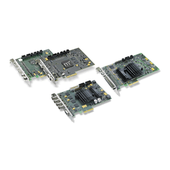
1.6 Introduction 1.6 Introduction The mvHYPERION-Series are frame grabbers for the bus system PCI Express®. The mvHYPERION frame grabber series for PCI Express® offers image processing with fast cameras using maximum capture bandwidth up to 1 G B/s. Depending on the model type, the frame grabbers are suitable for high-end machine vision applications with CameraLink cameras as well as broadcasting or surveillance solutions. -
Page 14: What's Inside And Accessories
The mvHYPERION series is suitable for following application areas: Figure 2: Application areas 1.6.1 What's inside and accessories Due to the varying fields of application the mvHYPERION series is shipped without accessories. The package contents: • mvHYPERION frame grabber Accessories for the mvHYPERION-CLx frame grabbers:... -
Page 15: Quickstart
1.7 Quickstart 1.7 Quickstart 1.7.1 Hardware installation Warning Please take all proper Electro Static Discharge (ESD) precautions during the installation of your new hardware! Before starting the installation, turn off your computer and all peripheral devices. Disconnect the computer from the power supply and all necessary components. -
Page 16: Software Installation
1.7.2.2 Software installation All necessary drivers for Windows and Linux are contained in the mvIMPACT CD-ROM or DVD-ROM. For newer driver versions we recommend to visit the MATRIX VISION website at www.matrix-vision.de, section Support/ Download/Hardware. After the Hardware installation (p. 11) the boot sequence shows "Found New Hardware" and starts the Windows Hardware Wizard. - Page 17 1.7 Quickstart Figure 2: mvHYPERION installer - Start window Select the folder, where you want to install the software. Figure 3: mvHYPERION installer - Select folder Select the features, which you want to install. Following features exist: MATRIX VISION GmbH...
- Page 18 • "Base Libraries" This feature contains all necessary files for property handling and display. Therefore, it is not selectable. • "mvHYPERION driver" This is also not selectable. • "Tools" This feature contains tools for the frame grabber (e.g. to acquire images (wxPropView (p. 42))). •...
- Page 19 1.7 Quickstart Figure 5: mvHYPERION installer - Confirm installation The installation process copies the files to Windows. Then Windows shows a message to signal that this driver is not checked through Microsoft. This is only an attempt to make insecure and it is recommended to ignore it. Press "Continue Anyway"...
-
Page 20: Linux
Figure 7: mvHYPERION installer - Driver successfully installed Figure 8: mvHYPERION installer -Installation complete After this, you have to restart the system. Afterwards, you can acquire images with the frame grabber. Simply start the application wxPropView (p. 42) (wxPropView.exe). See also wxPropView (p. -
Page 21: Installing The Mvimpact Acquire Driver
1.7 Quickstart • Linux x86 (32-bit) – The 32 bit version will run on a 64-bit Linux system if the other library requirements are met with 32-bit libraries. i.e. you cannot mix 64 and 32-bit libraries and applications. – Versions for Linux on x86-64 (64-bit), PowerPC, ARM or MIPS may be possible on request. •... - Page 22 1. Please start a console and change into a directory e.g. /home/username/workspace cd /home/username/workspace 2. Copy the install script and the hardware driver to the workspace directory (e.g. from a driver CD or from the website): ~/workspace$ cp /media/cdrom/drv/Linux/install_mvHYPERION.sh / .
- Page 23 1.7 Quickstart 1.7.3.2.2 Doing it manually The mvHYPERION is controlled by a number of user-space libraries. It is not necessary to compile a kernel module. 1. Logon to the PC as the user or start a super user session with .
- Page 24 Note Please declare the device e.g. HC or HC000000001 cd my_directory LD_LIBRARY_PATH=‘pwd‘/lib/x86 apps/SingleCapture/x86/SingleCapture HC * For 64-bit it will look like this... LD_LIBRARY_PATH=‘pwd‘/lib/x86_64 apps/SingleCapture/x86_64/SingleCapture HC * For ARM it will look like this... LD_LIBRARY_PATH=‘pwd‘/lib/arm apps/SingleCapture/arm/SingleCapture HC * etc. After installing the libraries and headers you may continue with "3." below as a normal user i.e. you do not need to be in order to compile the test applications.
-
Page 25: Connecting A Camera
1.7 Quickstart If you have more than one mvHYPERION in your PC you will need a device node per card: mknod /dev/hyperion0 c 64 0 mknod /dev/hyperion1 c 64 1 mknod /dev/hyperion2 c 64 2 mknod /dev/hyperion3 c 64 3 (e) The mvIMPACT Acquire libraries look for camera definition files in the directory "/etc/matrix-vision/mvimpact- so you will need to create these directories as the... - Page 26 Figure 9: wxPropView - Device setting start procedure • Please note that each setting location step in the figure from above internally contains two search steps. First the framework will try to locate a setting with user scope and if this can't be located, the same setting will be searched with global (system-wide) scope.
-
Page 27: Technical Data
1.8 Technical Data controls just calls the underlying function needed to write to the selected component. wxPropView (p. 42) also doesn't know about the type of component or e.g. the list of allowed values for a property. This again is information delivered by the driver and therefore can be queried by the user as well without the need to have special inside information. -
Page 28: Connectors
1.8.1.2 Connectors The mvHYPERION supports the serial communication over CameraLink™ cable as described in the Camera Link™ specification. The driver offers a serial interface without the need of a host PC's COM port. During the boot sequence of the operating system the serial interface is initialized. Normally, manufacturers of CameraLink™ cameras provide software to parameterize the camera. - Page 29 1.8 Technical Data Figure 6: Rev. 3.x Name Description FPGA state Green: FPGA is loaded PCI Express® x4 connection state Green: No problem with connection (PCI Express host supports 4 lanes) PCI Express® x1 connection state Green: No problem with connection (PCI Express host supports 1 lanes) Connector usage mvHYPERION...
- Page 30 Input 2+ Input 2+ Input 2+ Input 3- Input 3- Input 3- Input 3+ Input 3+ Input 3+ Xclk- Input 4- Yclk- Input 4- Yclk- Input 4- Xclk+ Input 4+ Yclk+ Input 4+ Yclk+ Input 4+ Input 5- Input 5- Input 5- Input 5+ Input 5+...
- Page 31 1.8 Technical Data Trigger-In1 (-) - Cathode Yellow Sync-In1 (+) - Anode Gray Sync-In1 (-) - Cathode Pink GND (camera power) Blue Pin. Signal Cable (KS99-0285) +12 V DC (0.7A/2A) (camera power) Strobe-Out2 (+) - Collector White Strobe-Out2 (-) - Emitter Brown Trigger-In2 (+) -...
- Page 32 13..16 GPOUT0..3 LVTTL(3.3V) output. not 5V tolerant! Ground Ground +12V DC Out +12V DC power supply +12V DC Out +12V DC power supply Ground Ground IDC multi-pin connector 2 x 10 Pol RM 2.54 x 2.54 mm. Note Pins are not opto-isolated, feature no EMC filter and are not protected against overload and overvoltage. Digital signals (pins 9-16) are LVTTL signals and not 5V tolerant.
- Page 33 1.8 Technical Data Figure 10: Trigger-In mvHYPERION-CLx MATRIX VISION GmbH...
- Page 34 Figure 11: Trigger-In mvHYPERION-CLx Figure 12: Trigger-Out mvHYPERION-CLx 1.8.1.2.9.1 Opto-isolated digital inputs TTL compatible threshold (standard): VIH, (VIH, max = maximum input voltage, which causes an active signal) max: VIH, (VIH, min = minimum input voltage, which causes an active signal) min: VIH, typ 5V..24V...
- Page 35 1.8 Technical Data Max. input frequency of the opto-isolated inputs: 10MHz An additional series resistor is not necessary at the inputs. The inputs own an internal current limitation and are protected up to -30V against polarity. 1.8.1.2.9.2 Opto-isolated digital output Attention The output is not overload protected and doesn't feature a free-wheeling diode! There are following conditions:...
-
Page 36: Components
IOL, max: 0.5V (IOL, max = maximum output voltage with internal driven inactive signal) IL, max: 3.5V (OL, max = maximum input voltage with internal driven inactive signal) 1.8.1.2.10.3 LVTTL-OC parameters (I2C-SDA) 1.8.1.3 Components mvHYPERION -CLb -CLe -CLm -CLf Video input Signal format CameraLink ™... -
Page 37: Device Feature And Property Lists
1.8 Technical Data Storage tempera- -20 up to 70 C ture Humidity 10 up to 90 % non-condensing Dimensions Length 147 mm 155 mm Width 95 mm 111.5 mm 1.8.1.4 Device Feature And Property Lists 1.8.1.4.1 mvHYPERION-CLm 1.8.2 mvHYPERION-32R16 1.8.2.1 Block diagram The following block diagram shows schematically how the mvHYPERION-32R16 is designed. -
Page 38: Connectors
1.8.2.2 Connectors Figure 14: mvHYPERION-32R16 Name Description PCI Express® connection state Green: No problem with connection FPGA state Green: FPGA is loaded 1.8.2.2.1 Status LEDs 1.8.2.2.2 Pinning J1 (68-pol connector) Figure 15: J1 Signal Note Signal Note Power 5V GND (G) VIDEO_15 GND (G) VIDEO30... -
Page 39: Components
1.8 Technical Data VIDEO29 Not used GND (G) VIDEO_13 GND (G) VIDEO28 Not used GND (G) VIDEO_12 GND (G) VIDEO27 Not used GND (G) VIDEO_11 GND (G) VIDEO26 Not used GND (G) VIDEO_10 GND (G) VIDEO25 Not used GND (G) VIDEO_9 GND (G) VIDEO24... -
Page 40: Mvhyperion-Hd-Sdi
Audio 2 (Cinch) Resolution Digitalization According to D1 digital video format Storage According to D1 digital video format Memory format YUV 4:2:2 packed/planar Interface PCI Express® x4 Continuous data rate Max. 640 MB/s Peak data rate Max. 1 GB/s Payload size Up to 256 Bytes Current consumption PCIe 3.3V... -
Page 41: Connectors
1.8 Technical Data Figure 16: mvHYPERION-HD-SDI-2 block diagram 1.8.3.2 Connectors Figure 17: mvHYPERION-HD-SDI-2 Connector usage mvHYPERION -HD-SDI-2 Camera 1 (3G/HD-SDI signal) Camera 2 (3G/HD-SDI signal) 1.8.3.2.1 Use of J1..J2 1.8.3.2.2 Pinning J5 (15-pol D-SUB/HD connector) MATRIX VISION GmbH... - Page 42 Figure 18: J5 Signal Signal direction Level Sync-Out 1 (Trilevel, 75R) 1Vss (75R) Sync-Out 2 (Trilevel, 75R) 1Vss (75R) Sync-Out 3 (Trilevel, 75R) 1Vss (75R) IN/OUT TTL (open collector) Digital Ground RS-485 Ground Sync-Out 1 Ground Sync-Out 2 Ground Sync-Out 3 Camera Power Supply +5VDC / =10W (optional +12VDC)
-
Page 43: Components
1.8 Technical Data Note Pins are not opto-isolated, feature no EMC filter and are not protected against overload and overvoltage. Digital signals (pins 9-16) are LVTTL signals and not 5V tolerant. Failure to take this into account may result in the destruction of the board. Attention Without an additional card with corresponding snubbers these signals must not conducted! 1.8.3.3 Components... - Page 44 Max. Format Frequency Video Physical Standard Comment chan- (fps) tim- layer data nels ing/ data map- ping 1080p 23. :2:2 292- (2x10 Bit) 1080p 50, Only chan- :2:2 424- (2x10 sup- Bit) ported; Level Firmware ver- sion Acquisition of 2 independent standard quired.
- Page 45 1.8 Technical Data Max. Format Frequency Video Physical Non- Comment chan- (fps) tim- layer standard nels ing/ data data map- ping 1080p 23. Raw(2k), Raw(12 Bit) 292- 1080p 50, Raw(12 Firmware Bit) ver- sion 424- Level quired. 1080p 50, Raw(2k) O nly chan- 424- sup-...
-
Page 46: Gui Tools
Interface PCI Express® x4 Continuous data rate Max. 640 MB/s Peak data rate Max. 1 GB/s Payload size Up to 256 Bytes Current consumption PCIe 3.3V Max. 1A PCIe 12V Max. 0.05A + camera power Camera supply Via PCI Express® 12V fused Environmental conditions Ambient temperature 0 up to 45 C... -
Page 47: Mvipconfigure
1.9 GUI tools 1.9.4 mvIPConfigure With mvIPConfigure it is possible • to configure the network behavior of GigE Vision™ devices • to determine and solve network issues. 1.9.5 mvGigEConfigure With mvGigEConfigure it is possible • to install, remove or configure the MATRIX VISION GigE Vision™ capture filter driver. See also For further information about the tools, please follow the link to the separate manual describing the GUI tools in great detail on our website:... -
Page 48: Hrtc - Hardware Real-Time Controller
1.10 HRTC - Hardware Real-Time Controller 1.10.1 Introduction The Hardware Real-Time Controller (HRTC) is built into the FPGA. The user can define a sequence of operating steps to control the way how and when images are exposed and transmitted. Instead using an external PLC, the time critical acquisition control is directly build into the frame grabber . -
Page 49: How To Use The Hrtc
1.10 HRTC - Hardware Real-Time Controller 1.10.2 How to use the HRTC To use the HRTC you have to set the trigger mode and the trigger source. With object orientated programming languages the corresponding camera would look like this (C++ syntax): CameraSettingsFrameGrabber->triggerMode.writeS("On");... -
Page 50: Developing Applications Using The Mvimpact Acquire Sdk
1.11 Developing applications using the mvIMPACT Acquire SDK mvIMPACT Acquire SDK is a comprehensive software library that can be used to develop applications using the devices described in this manual. A wide variety of programming languages is supported. For C, C++, .NET, Python or Java developers separate API descriptions can be found on the MATRIX VISION website: •... -
Page 51: Directshow Interface
1.12 DirectShow interface 1.12 DirectShow interface Note DirectShow can only be used in combination with the Microsoft Windows operating system. Since Windows Vista, Movie Maker does not support capturing from a device registered for DirectShow anymore. This is the documentation of the MATRIX VISION DirectShow_acquire interface. A MATRIX VISION specific prop- erty interface based on the IKsPropertySet has been added. -
Page 52: Setting Up Devices For Directshow Usage
1.12.3 Setting up devices for DirectShow usage In order to be able to access a device through the mvIMPACT Acquire driver stack from an application through DirectShow a registration procedure is needed. This can either be done using mvDeviceConfigure or by a command line tool that is part of the Windows operating system. - Page 53 1.12 DirectShow interface 2. To register every installed device for DirectShow access click on the menu item "DirectShow" "Register All Devices". mvDeviceConfigure - Register All Devices 3. After a successful registration the column "Registered For DirectShow" will display "yes" for every device and the devices will be registered with a default DirectShow friendly name which is displayed in the "DirectShow Friendly Name"...
-
Page 54: Renaming Devices
1.12.3.2 Renaming devices To modify the DirectShow friendly name of a device: 1. mvDeviceConfigure needs to be started(with elevated rights). 2. right-click on the device to rename and select "Set DirectShow Friendly Name": mvDeviceConfigure - Set DirectShow Friendly Name 3. Then, a dialog will appear. Please enter the new name and confirm it with "OK". mvDeviceConfigure - Dialog For New Name MATRIX VISION GmbH... -
Page 55: Using Regsvr32
1.12 DirectShow interface 4. Afterwards the column "DirectShow friendly name" will display the newly assigned friendly name. mvDeviceConfigure - Renamed Device Note Please do not select the same friendly name for two different devices. In theory this is possible, however the mvDeviceConfigure GUI will not allow this to avoid confusion. -
Page 56: Glossary
1.13 Glossary A/D reference Upper threshold of video signal to be digitized. All values above this limit value are digitized to 255. Increasing the reference level results in contrast deterioration and vice versa. Analog to digital converter (A/D converter) Resolution Number of pixels (horizontal x vertical) Base address Starting address from which the memory or register are inserted. -
Page 57: Use Cases
1.14 Use Cases Square pixels Square-shaped pixels (height-width ratio 1:1) RS170 US video standard for 60 Hz b/w colors TFT display Thin film transistor display True color 24-bit true color; 16.7 million colors Vertical sync Synchronization pulse in video signal for field end recognition. Zero signal The zero signal was needed with the old frame grabbers, to calibrate the analog/digital converter (ADC) (signal and parameter aren't important anymore). -
Page 58: Working With Pulse Start Events
Figure 1: wxPropView - Digital I/O - Pass-through of a digital signal 1.14.1.2 Working with pulse start events The pulse start configuration list represents a (HRTC) as known from Hardware Real-Time Controller USB 2.0 camera mvBlueFOX. The mvHYPERION features two HRTC's (PulseStartConfiguration0 and PulseStart Configuration1). -
Page 59: Working With An Rotary Encoder
1.14 Use Cases Figure 1: wxPropView - Pulse start sample • Working with an rotary encoder (p. 55) – parameters * external signals from a rotary encoder, which starts the pulse sequence initially - "Rotary Decoder" * decode the signals of the rotary encoder. See also Working with an rotary encoder (p. - Page 60 Figure 1: Principle of an rotary encoder Figure 2: Gray code signal at the output of the two data lines As described in Working with pulse start events (p. 54) the mvHYPERION features two HRTC's (PulseStart Configuration0 and PulseStartConfiguration1), which also features a Rotary Decoder (p. 55). MATRIX VISION GmbH...
- Page 61 1.14 Use Cases Figure 3: wxPropView - Selecting RotaryDecoder as PulseStartTrigger in PulseStartConfiguration0 The Rotary Decoder (p. 55) offers some parameters: • DigitalSignalA (p. 57) • DigitalSignalB (p. 57) • PulseMultiplication (p. 57) • Direction (p. 58) • Mode (p. 58) •...
- Page 62 Figure 4: Pulse multiplication 1.14.1.3.4 Direction Specifies the direction of rotation. 1.14.1.3.5 Mode Here you can specify the mode of the encoder. There are three different modes: • "NoInhibit": The direction of rotation is not relevant. • "InhibitBackward": The direction of rotation is relevant. This means, if the direction is changed, the edges will be ignored.
-
Page 63: Working With A Basler Sprint Line Scan Color Camera
1.14 Use Cases Figure 5: wxPropView - Selecting modes Note With the property "Divider" you can set if every signal (or every second, third etc.) from the rotary encoder is used. 1.14.1.3.6 int Reset() With this function you can reset the counter, which is saved in InhibitBackwardUntil LastPos (p. - Page 64 To guarantee the BayerParity start condition, the camera sends a FrameValid synchronization signal. Thus, you can say that the camera behaves like a area-scan camera. With Basler's camera control tool you can define the frame height (always a multiple of 2) and therefore the Frame Valid signal.
- Page 65 1.14 Use Cases Figure 2: wxPropView - Trigger start condition The following sections show how you have to set the mvHYPERION according to the different modes. 1.14.1.4.2 RawLineAcquisition Mode In this mode, the camera sends the color lines alternately. For more details about this mode, please have a look at the camera's manual.
- Page 66 Figure 3: wxPropView - Height (H), Format Bayer, BayerParity, ScanMode, line scanStartCondition Although we defined a line scan camera in the ScanMode, the mvHYPERION has to handle the FrameValid syn- chronization. With line scanStartCondition the mvHYPERION runs in a mode, which waits for a FrameValid signal when the image starts.
- Page 67 1.14 Use Cases Figure 4: wxPropView - Triggered acquisition with area-scan cameras 1.14.1.4.3 EnhancedRawLineAcquisition Mode The camera also offers a special mode called "Enhanced Raw Line Acquisition Mode". It provides a raw "green" pixel value for each point of an imaged object and, in addition, either a raw "red"...
- Page 68 Figure 5: wxPropView - Settings Height (H), Format BayerPacked, BayerParity, ScanMode, line scanStartCondition It only makes sense to reproduce this application using a rotary encoder (p. 55). The application could look like this: MATRIX VISION GmbH...
- Page 69 1.14 Use Cases Figure 6: Conveyor belt with rotary decoder The camera line synchronization in this sample is the trigger signal of a rotary encoder. Afterwards, two SinglePulse signals are sent via digital out CC1: MATRIX VISION GmbH...
-
Page 70: Working With Trigger Events
Figure 7: wxPropView - Triggered acquisition with area-scan cameras Note With the property "Divider" you can set if every signal (or every second, third etc.) from the rotary encoder is used. 1.14.1.5 Working with trigger events One or many trigger(s) can be used to control start of an acquisition, of a frame of an acquisition or each line of a frame (for line scan devices). - Page 71 1.14 Use Cases Typically, a trigger event has a • falling edge and a • rising edge. A falling edge initializes the capture of a frame (see Figure 1). Figure 1: Typical trigger events There are three modes to use trigger events with mvHYPERION frame grabbers: •...
- Page 72 It is also possible to define a trigger delay via • "TriggerDelayAbs_us" • "TriggerDelayLines" , which only makes sense using line scan cameras. Figure 3: wxPropView - Possible trigger sources Figure 4: wxPropView - Possible trigger activations MATRIX VISION GmbH...
- Page 73 1.14 Use Cases With the property "TriggerDivider" it is possible to define, which trigger events are regarded (see Figure 5). Figure 5: Trigger divider 1.14.1.5.2 FrameStart + FrameStop In this mode you have two signal definitions. With the appearance of the stop event, the image acquisition will be stopped line-synchronously and the amount of acquired lines will be available as result or image information.
- Page 74 Figure 7: wxPropView - Second trigger on 1.14.1.5.2.1 FrameStart + FrameStop (with restart option using the same event) In this mode every trigger event is accepted at any time during active image acquisition. If a trigger event happens during an acquisition, the acquisition will be stopped line-synchronously even if all requested lines of the previous image have not been acquired completely.
- Page 75 1.14 Use Cases Figure 9: wxPropView - Trigger overlap Using line scan cameras, it is possible to define a delay using "TriggerDelayLines" . With it you can shift, for example, the FrameStart. 1.14.1.5.3 AcquisitionStart Some cameras like line scan cameras send "FrameValid"...
-
Page 76: Synchronous Acquisition With Different Camera Settings
1.14.1.6 Synchronous acquisition with different camera settings For details, how you can create a synchronous acquisition with different camera settings in wxPropView (p. 42) is described in section "Setting Up Multiple Display Support, Working With Several Capture Settings In Parallel" in the "mvIMPACT Acquire SDK GUI Applications"... - Page 77 1.14 Use Cases Figure 2: wxPropView - Digital I/O - ControlMode 3. Now, you can create a HRTC program in "Digital I/O - HardwareRealTimeController". Figure 3: wxPropView - Digital I/O - HardwareRealTimeController - HRTC program The HRTC program consist of 5 steps: (a) Wait for an "Off"...
- Page 78 Figure 4: wxPropView - Digital I/O - HardwareRealTimeController (c) Then, a pulse signal is set to "On" at the "TriggerController" (in this sample at position 9 which is shown in the help window). (d) Afterwards, the pulse signal is "Off" again. MATRIX VISION GmbH...
- Page 79 1.14 Use Cases Figure 5: wxPropView - Digital I/O - HardwareRealTimeController (e) Finally, the program jumps back to step 0. 4. Now, if you have a rotary encoder and you have connected the signal A to the "Sync-In", you can bypass this signal, for example, to CC1: MATRIX VISION GmbH...
-
Page 80: Using Video Stream Recording
Figure 6: wxPropView - Digital I/O - Pass-through of a digital signal Now, if all two capture settings for both cameras have • the "TriggerSource" set to "HRTCtrl_0", • the "TriggerMode" to "On" and • the "TriggerActivation" set to "FallingEdge", as shown in Figure 2 for the "Base"... -
Page 81: Requirements
1.14 Use Cases 1.14.2.1 Requirements Since the mvIMPACT Acquire API internally uses FFmpeg to record video streams, the FFmpeg libraries need to be present on the target system as well. They can either be built OR installed into the systems default library search path OR installed somewhere and afterwards an environment variable MVIMPACT_ACQUIRE_FFMPEG_DIR can be defined that points to the folder containing the libraries. - Page 82 Figure 1: Set up pixel format in ImageDestination 2. Start "Setup Video Stream Recording...". MATRIX VISION GmbH...
- Page 83 1.14 Use Cases Figure 2: Set up video stream recording 3. Click 'Yes' to create a video file for the compressed stream, choose the desired codec and the compression quality. Figure 3: Setup Video Stream Recording... Figure 4: Name the video file MATRIX VISION GmbH...
- Page 84 Figure 5: Choose the video codec Figure 6: Choose the video compression quality 4. Click 'Acquire' to start streaming. Figure 7: Click 'Acquire' to start streaming 5. Open "Setup Video Stream Recording..." and click 'Cancel' to stop recording. MATRIX VISION GmbH...
-
Page 85: Recording Using The Api
1.14 Use Cases Figure 8: Click 'Cancel' to stop recording 1.14.2.3 Recording Using The API Please refer to the example on how to record a video stream using mvIMPACT Acquire C++ API: Continuous CaptureFFmpeg.cpp or have a look at the VideoStream class. -
Page 86: Working With Gain And Black-Level Values Per Color Channel
1.14.3 Working With Gain And Black-Level Values Per Color Channel In many low-lighting applications the gain needs to be increased to enhance the brighness of the images. However, while the image brightness is increased, the black-level of the image is also increased, which in many cases should be avoided. - Page 87 1.14 Use Cases Figure 2: The GainOffsetKnee filter option in wxPropView 2. Once the GainOffsetKnee filter is activated, the configuration field will be displayed (see Figure 3). As an example, the current RGB image is shown in Figure 4 and its histogram in Figure 5. Figure 3: The configuration field for the GainOffsetKnee filter MATRIX VISION GmbH...
- Page 88 Figure 4: An image without the GainOffsetKnee filter Figure 5: The histogram of Figure 3 3. The overall offset can be assigned using the 'GainOffsetKneeMasterOffset_pc'. A positive offset increases the black-level of the image, whereas a negative offset reduces it. To visualize the effect, an offset of 5% is given as an example, which means that the overall black-level of the image will be increased by 5% of the max.
- Page 89 1.14 Use Cases Figure 6: Assign overall/master offset to the image Figure 7: The image with 5% overall offset MATRIX VISION GmbH...
- Page 90 Figure 8: The histogram with 5% overall offset 4. Among the GainOffsetKneeChannels there are 4 channels. For mono images, only channel 0 is used. For RGB images, channel 0-2 are used: red channel, green channel and blue channel respectively. For Bayer images, channel 0-3 are used.
- Page 91 1.14 Use Cases Figure 10: The image with 1.0625dB gain in the red channel Figure 11: The histogram with 1.0625dB gain in the red channel 5. The individual black-level can be assigned using the channel specific 'Offset_pc'. Analogous to 'GainOffset KneeMasterOffset_pc', a positive offset increases the black-level of the channel, whereas a negative offset reduces it.
- Page 92 Figure 12: Assign individual offset to the red channel Figure 13: The image with 5% offset in the red channel MATRIX VISION GmbH...
-
Page 93: Configuration Using The Api
1.14 Use Cases Figure 14: The histogram with 5% offset in the red channel 1.14.3.2 Configuration Using The API Depending on the programming language you are working with the names of classes, namespaces and proper- ties might vary slightly. For C++ please refer to the GainOffsetKneeChannelParameters class and Image Processing... - Page 94 MATRIX VISION GmbH...
Need help?
Do you have a question about the mvHYPERION Series and is the answer not in the manual?
Questions and answers