
Related Manuals for Samoa LARIUS SIRIO 60:1


Summary of Contents for Samoa LARIUS SIRIO 60:1
- Page 1 w w w . l a r i u s . c o m SIRIO 60:1 Airless pneumatic pump for extrusion Code: 99500 II 2G c IIB T6...
- Page 2 This manual is to be considered as an English language translation of the original manual in Italian. The manufacturer shall bear no responsibility for any damages or inconveniences that may arise due to the incorrect translation of the instructions contained within the original manual in Italian. Due to a constant product improvement programme, the factory reserves the right to modify technical details mentioned in this manual without prior notice.
-
Page 3: Table Of Contents
SIRIO 60:1 SIRIO 60:1 Airless pneumatic pump for extrusion INDEX WARNINGS ..................................2 WORKING PRINCIPLE ..............................3 TECHNICAL DATA ................................4 DESCRIPTION OF THE EQUIPMENT ..........................5 TRANSPORT AND UNPACKING ..........................7 GUARANTEE CONDITIONS ............................7 SAFETY RULES ................................7 TYPICAL INSTALLATION ..............................8 SETTING ..................................9 OPERATION..................................9 CLEANING AT THE END OF THE WORK ........................10 ROUTINE MAINTENANCE ............................10 DISASSEMBLY AND REASSEMBLY OF THE PUMPING UNIT ..................11 MANUAL RESET OF THE PNEUMATIC MOTOR .......................25... -
Page 4: Awarnings
SIRIO 60:1 WARNINGS The table below provides the meaning of the symbols used in this manual in relation to using, earthing, operating, maintaining, and repairing of this equipment. • Read this operator’s manual carefully before using the equipment. • An improper use of this machine can cause injuries to people or things. •... -
Page 5: Bworking Principle
SIRIO 60:1 WORKING PRINCIPLE The pneumatic transfer pumps work with a compressed air motor number of cycles that it completes (the cycle is the full stroke of that moves the piston vertically from top to bottom and viceversa. the piston in both direction). The product is suctioned by the lower pump and carried to the exit. -
Page 6: Ctechnical Data
SIRIO 60:1 TECHNICAL DATA SIRIO 60:1 Pump feed air pressurea 3-7 bar Maximum pressure of the product 420 bar Feed air inlet 3/4” BSPP Material exit 4 l/min Maximum delivery 3/4” BSPP Weight 35 Kg Noise pressure level <80 dB (A) Dimensions 1020 mm 270 mm... -
Page 7: Ddescription Of The Equipment
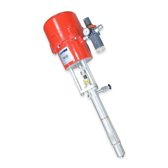
SIRIO 60:1 DESCRIPTION OF THE EQUIPMENT Fig. 1D Pos. Description Pos. Description Pump supply air input Material outlet Manometer reading air pressure alim. pump Follower plate Feed air pressure regulator. pump Bleed valve Lubricant bucket Nut to press seal Material pumping group www.larius.com ED. - Page 8 SIRIO 60:1 MADE IN ITALY SIRIO RAPPORTO RATIO MASSIMA PRESSIONE FLUIDO PORTATA MASSIMA Fig. 2D Pos. Description Pos. Description Pneumatic motor Cable grounding with gripper Follower plate CE Plate Sound absorbing filter www.larius.com ED. 04 - 11/2020 - Cod. 150170...
-
Page 9: Etransport And Unpacking
SIRIO 60:1 TRANSPORT AND SAFETY RULES UNPACKING Read carefully and entirely the following instructions before using the product. Please save these • The packed parts should be handled as indicated in the symbols instructions in a safe place. and markings on the outside of the packing. •... -
Page 10: Htypical Installation
SIRIO 60:1 FOR CONNECTION BETWEEN PUMP, FLEXIBLE HOSE AND If the product to be used is toxic, avoid inhalation SPRAY GUN BEFORE USING THE EQUIPMENT. and contact by using protection gloves, goggles • ALWAYS USE THE FLEXIBLE HOSE SUPPLIED WITH STAN- and proper face shields. -
Page 11: Isetting
SIRIO 60:1 SETTING-UP At the start of each working day, make sure that the ring nut is filled with hydraulic oil (ref. 16340); the oil facilitates the sliding of the piston and PUMP FASTENING ON THE RAM prevents any material which may have leaked For the correct fastening of the pump on the ram, use the holes out of the seals from drying once the equipment placed on the base of the pneumatic motor. -
Page 12: Cleaning At The End Of The Work
SIRIO 60:1 CLEANING AT THE END OF THE WORK • Point the spray gun or the delivery valve at a container and By “cleaning at the end of the work” is meant the cleaning to drain all the product left inside the pump till a clean solvent carry out in case of use with a different product or if a long period comes out. -
Page 13: Mdisassembly And Reassembly Of The Pumping Unit
SIRIO 60:1 DISMANTLING AND REASSEMBLING THE PUMPING UNIT Always close the compressed air supply and release the pressure in the plant beforecarrying out the disassembly of the pumping group. In case the product being used is toxic, follow the procedure of cleaning described on page 8 to avoid the contact with the product during the disassembly of the pumping group. - Page 14 SIRIO 60:1 Necessary tools and equipment Procedure 2.1 Disconnect the components (2a) of the pump (2b) Fig. 2M Necessary tools and equipment Procedure 3.1 Disconnect the pumping group (3a) from the motor (3b) Fig. 3M www.larius.com ED. 04 - 11/2020 - Cod. 150170...
- Page 15 SIRIO 60:1 Necessary tools and equipment Procedure 4.1 Unscrew the three nuts (4a), (4b) and (4c) using a wrench (4d) Fig. 4M Necessary tools and equipment Procedure 5.1 Slide the complete pumping group Fig. 5M www.larius.com ED. 04 - 11/2020 - Cod. 150170...
- Page 16 SIRIO 60:1 Necessary tools and equipment Procedure 6.1 Remove the component (6a) 6.2 Slide off the component (6b) 6.3 Loosen the ring nut (6c) with pin (6d) 6.4 Unscrew and remove the ring nut (6e) Fig. 6M www.larius.com ED. 04 - 11/2020 - Cod. 150170...
- Page 17 SIRIO 60:1 Necessary tools and equipment Procedure 7.1 Push downwards the motor piston rod (7a) till the shovel plate comes out of the housing (7b) Fig. 7M Necessary tools and equipment Procedure 8.1 Unscrew and remove the components (8a), (8b) e (8c) Fig.
- Page 18 SIRIO 60:1 Procedure 9.1 Unscrew the cylinder (9a), remove the washer (9b) and the shutter housing (9c) Fig. 9M Necessary tools and equipment Procedure 10.1 Unscrew the component (10a) and slide the rod (10b) 10.2 Unscrew the component 10c) and remo- ve the copper rings (10d) Fig.
- Page 19 SIRIO 60:1 Necessary tools and equipment CLEANER Procedure 11.1 Remove the superior seals 11.2 Clean and lubricate the gasket housing and replace it with the new spare parts (11a) SUPERIOR SEALS NOTE Follow the direction of rotation of gaskets A: Female STEEL ring cod. 96984 Direction B: White gasket cod.
- Page 20 SIRIO 60:1 Necessary tools and equipment CLEANER Procedure 12.1 Remove the inferior seals 12.2 Clean and lubricate the gasket housing and replace it with the new spare parts (12a) NOTE Follow the direction of rotation of gaskets Direction INFERIOR of assembly SEALS Fig.
- Page 21 SIRIO 60:1 Necessary tools and equipment CLEANER Procedure 14.1 Unscrew the component (14a) and slide the rod 14.2 Clean and lubricate the gasket housing and replace it with the new spare parts (14b) PTFE Polietilene Direction of assembly Fig. 14M www.larius.com ED.
- Page 22 SIRIO 60:1 Necessary tools and equipment CLEANER Procedure 15.1 Unscrew the component (15a) and slide the rod 15.2 Check the wear of components (15b) and (15c) and replace it if necessary 15.3 Clean and lubricate the threaded area and reassemble the component Fig.
- Page 23 SIRIO 60:1 Necessary tools and equipment Procedure 17.1 Insert the component (17a) and screw the rod 17.2 Insert the copper rings , reassemble the component (17b) and insert the rod (17c) 17.3 Screw the component (17d) Fig. 17M www.larius.com ED. 04 - 11/2020 - Cod. 150170...
- Page 24 SIRIO 60:1 Necessary tools and equipment Procedure 18.1 Reassemble the washer and the shutter housing and screw the cylinder (18a) 18.2 Reassemble shovel plate (18b) and insert the motor piston Fig. 18M Necessary tools and equipment Procedure 19.1 Insert e screw the ring nut (19a) 19.2 Fix the ring nut (19b) with the pin (19c) Fig.
- Page 25 SIRIO 60:1 Necessary tools and equipment Procedure 20.1 Insert the component (20a) 20.2 Insert the component (20b) and and screw with the wrench Fig. 20M Necessary tools and equipment Procedure 20.1 Insert the complete pumping group (21a) 20.2 Screw the three nuts using two wrench Fig.
- Page 26 SIRIO 60:1 Necessary tools and equipment Procedure 22.1 Connect the pumping group (22a) to motor (22b) Fig. 22M Necessary tools and equipment Procedure 23.1 Connect the component (23a) to pump (23b) Fig. 23M www.larius.com ED. 04 - 11/2020 - Cod. 150170...
-
Page 27: Nmanual Reset Of The Pneumatic Motor
SIRIO 60:1 Necessary tools and equipment Procedure 24.1 Reassemble the shovel plate Fig. 24M MANUAL RESET OF THE PNEUMATIC MOTOR • The feed air pressure of the pump must never be higher than the maximum value indicated in the technical data. Exceed this value can block the valves of the pneumatic motor in the intermediate position of the cycle reversal. -
Page 28: Odismantling And Reassembling The Pneumatic Motor
SIRIO 60:1 DISMANTLING AND REASSEMBLING THE PNEUMATIC MOTOR Necessary tools and equipment Procedure 1.1 Close the compressed air supply to the pump and release the residual pressure in the plant. 1.2 Unscrew the motor cap (1a) and pull it upwards together with the guide rod (1b) (1e) 1.3 Hold the guide rod (1b) and remove the plug (1a) (using two wrenches). - Page 29 SIRIO 60:1 Necessary tools and equipment Procedure 2.1 Remove the screws (2a) and the washers (2b). (2c)(2d) Fig. 2O Procedure 3.1 Carefully extract the motor cylinder (3a) fom the pump. Fig. 3O www.larius.com ED. 04 - 11/2020 - Cod. 150170...
- Page 30 SIRIO 60:1 Necessary tools and equipment Procedure 4.1 Unscrew the nut (4a), holding the guide rod with a 7mm wrench. Then reassemble the cap (4b). Fig. 4O Procedure 5.1 Press at the point (5a) to snap inside the rocker arm stud screw Fig.
- Page 31 SIRIO 60:1 Necessary tools and equipment Procedure 7.1 Use a screwdriver to lever the lower part of the stud screw (7a), keeping a hand over the cap to accompany it. (7b) Fig. 7O Necessary tools and equipment Procedure 8.1 Remove the two valve screws (8a, 8b) Fig.
- Page 32 SIRIO 60:1 Necessary tools and equipment Procedure 10.1 Lubricate the springs (10a, 10b). Fig. 10O Necessary tools and equipment CLEANER Procedure 11.1 Remove the OR gasket (11a) and replace it if necessary with a spare part Fig. 11O Necessary tools and equipment Procedure 1 2 .
- Page 33 SIRIO 60:1 crosspiece valve screw Procedure 12.2 Reassemble the two valve screws, inserting a 3.5 mm thickness gauge as shown in the drawing and adjusting the exact position of the stud screw as shown in the drawing, keeping a tolerance distance of 3.5 mm NOTE Make adjustments in the same way on both...
- Page 34 SIRIO 60:1 Necessary tools and equipment Procedure 14.1 Lubricate the gasket (14a) 14.2 Carefully reassemble the motor cylinder (14b) on the pump. Fig. 14O Necessary tools and equipment Procedure 15.1 Re-screw in the 6 screws (15a) and the washers (15b), (15c), (15d) Fig.
- Page 35 SIRIO 60:1 Necessary tools and equipment Procedure 16.1 Raise the central guide rod (16b) from inside the cylinder (16d) 16.2 Remove the nut (16c) 16.3 Re-screw the cap (16a) onto the rod using 2 wrenches and re-screw in the cap on the cover (16e) Fig.
-
Page 36: Pproblems And Solution
SIRIO 60:1 PROBLEMS AND SOLUTION Problem Possible cause Solution The pump does not start Feed air not sufficient; Check on the air supply line. Increase the diameter of the feed hose; Outlet product line clogged; Open the recirculation tap to check whether the pump starts up. -
Page 37: Spare Parts
SIRIO 60:1 SPARE PARTS Pneumatic regulator pag. 37 Complete pneumatic motor pag. 36 Complete pump pag. 38 www.larius.com ED. 04 - 11/2020 - Cod. 150170... -
Page 38: Qcomplete Pneumatic Motor
SIRIO 60:1 COMPLETE PNEUMATIC MOTOR Ref . 99100 WARNING: always indicate code and quantity for each part required. MADE IN ITALY SIRIO RAPPORTO RATIO MASSIMA PRESSIONE FLUIDO PORTATA MASSIMA COMPLETE ROCKER ARM COMPLETE SCREW VALVE COMPLETE BUSH NOT INCLUDED NON COMPRESA IN THE MOTOR ASSEMBLY NELL’ASSIEME MOTORE www.larius.com... -
Page 39: Rpneumatic Regulator Unit
SIRIO 60:1 Pos. Code Description Q. ty Pos. Code Description Q. ty 99100 Complete motor 99057 Valve screw 96050 Motor base 99058 Valve gasket 33005 Washer Ø 10 96011 Guide spring 16111 Screw 96025 Screw Tce 99270 Elbow fitting 99059 O-ring 99054 Sound absorbing filter... -
Page 40: Spumping Group
SIRIO 60:1 EXPLODED VIEW OF PUMPING STANDARD GROUP 99550 - PUMPING LONG 99553 WARNING: always indicate code and quantity for each part required. www.larius.com ED. 04 - 11/2020 - Cod. 150170... - Page 41 SIRIO 60:1 Pos. Code Description Q. ty Pos. Code Description Q. ty 96073 O-ring 96878 Female ring for middle gaskets 96860 Connection sleeve 96883 Copper gaskets 96712 Standard joining extension cable 96897 Housing for lower gaskets 96803 Long joining extension cable 96889 Seal 3323...
-
Page 42: Taccessories
SIRIO 60:1 ACCESSORIES MANUAL REVOLVING SPRAY LA 95 SPRAY GUN GUN EXT 85 M16X1,5 Description Available fittings Manual for pneumatic sealing Fixed fitting 3/8" Manual for sealing Fixed fitting 1/4" Fixed fitting M16X1,5 LA 95 SPRAY GUN Description Inox for automatic sealing PNEUMATIC HOIST complete with compressed air regulators and pressure gauges Description Pneumatic hoist for drums from 30 to max 200 litres with double-effect single cylinder... - Page 43 SIRIO 60:1 REGULATORS REGULATORS EXTRUSION DISCS Description Description Description High pressure regulator for recirculation Automatic regulator for mastics Extrusion disc with single flat gasket for 10-130 bar lt.200 drums series Ghibli 24:1-Nova 55:1 High pressure regulator Regulator for mastics Extrusion disc with single flat gasket for lt.30 drums series Ghibli 24:1 EXTRUSION REGULATORS KIT EXTRUSION REGULATORS KIT...
-
Page 44: Atex Certificate
SIRIO 60:1 ATEX CERTIFICATE www.larius.com ED. 04 - 11/2020 - Cod. 150170... -
Page 45: Declaration Of Conformity
SIRIO 60:1 CE DECLARATION OF CONFORMITY Company LARIUS srl Via Antonio Stoppani 21 - 23801 Calolziocorte (LC) ITALY Tel: +39 0341 621152 Fax: +39 0341 621243 E-mail: larius@larius.com Declares under his owns resonsibility that the product: SIRIO 60:1 Airless pneumatic pump for extrusion complies with the directives: - EC Directive 2006/42 Machinery Directive furthermore to the... - Page 46 LARIUS srl Via Antonio Stoppani 21 - 23801 Calolziocorte (LC) ITALY TEL. +39 0341 621152 - Fax +39 0341 621243 - larius@larius.com www.larius.com...
Need help?
Do you have a question about the LARIUS SIRIO 60:1 and is the answer not in the manual?
Questions and answers