
Subscribe to Our Youtube Channel
Related Manuals for Banner SSA-EB1PL 0D Series


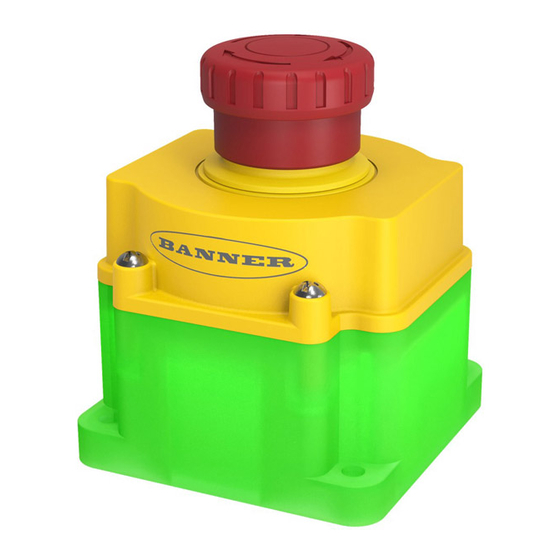
Summary of Contents for Banner SSA-EB1PL 0D Series
- Page 1 SSA-EB1PLx-0Dx Series Lighted Emergency Stop Button with ISD Instruction Manual Original Instructions 215157 Rev. A 3 August 2020 © Banner Engineering Corp. All rights reserved 215157...
-
Page 2: Table Of Contents
5 Product Support and Maintenance ..........................18 5.1 Maintenance and Service ................................18 5.2 Status Indicators ....................................18 5.3 EU Declaration of Conformity (DoC) .............................. 18 5.4 Information Available Using ISD ..............................18 5.5 Contact Us .....................................20 5.6 Banner Engineering Corp. Limited Warranty ..........................20... -
Page 3: Product Overview
The user is responsible for satisfying all local, state, and national laws, rules, codes, and regulations relating to the use of this product and its application. Banner Engineering Corp. has made every effort to provide complete application, installation, operation, and maintenance instructions. Please contact a Banner Applications Engineer with any questions regarding this product. -
Page 4: Emergency Stop Considerations
The OSSDs remain in this condition until the push button is manually re-armed by pulling or twisting clockwise the red push button actuator. The SSA-EB1PLx-0Dx..ECQ.. series has a 30 mm mounting base similar to Banner's OTB, VTB, and STB Optical Touch Buttons for ease of mounting without requiring an additional enclosure. The SSA-EB1PLx-0Dx..ED1Q.. series has a flat mounting base for ease of mounting without requiring an additional enclosure. -
Page 5: Installation Instructions
SSA-EB1PLx-0Dx Series Lighted Emergency Stop Button with ISD 2 Installation Instructions 2.1 Mechanical Installation The SSA-EB1PLx-0Dx Series Lighted Emergency Stop Button with ISD is supplied with all necessary mounting hardware. Important: Install the emergency stop in a manner that discourages tampering or defeat. Mount emergency stops to prevent bypassing at the terminal chamber or quick disconnect (QD) connection. -
Page 6: Output Signal Switching Devices (Ossds) And External Device Monitoring (Edm)
To ensure proper operation, the Banner device output parameters and machine input parameters must be considered when interfacing the Banner device OSSD outputs to machine inputs. Design the machine control circuitry so that the maximum load resistance value is not exceeded and the maximum specified OSSD Off-state voltage does not result in an On condition. -
Page 7: Fault-Tolerant Output Feature
The SSA-EB1PLx-0Dx Series Lighted Emergency Stop Button with ISD can be connected in series or individually to a compatible Banner XS26-2 or SC10-2ro Safety Controller. See the XS26-2/SC10 Safety Controller Instruction Manual for additional details regarding input terminal combinations compatible with ISD. -
Page 8: Wire The Device In Series Using The Quick Disconnect (Qd)
SSA-EB1PLx-0Dx Series Lighted Emergency Stop Button with ISD SSA-EB1PL.. 1 SSA-EB1PL.. 2 SSA-EB1PL.. 3 – – – n.c. n.c. n.c. Safety Controller Figure 6. Series connection of multiple SSA-EB1PLx-0Dx.. without reset function wiring diagram. SSA-EB1PL.. Q8R 1 SSA-EB1PL.. Q8R 2 SSA-EB1PL.. - Page 9 SSA-EB1PLx-0Dx Series Lighted Emergency Stop Button with ISD Power Safety Reset Monitoring Module ONLY FOR E-Stop 4 DEE2R-8xxD 24Vdc 0Vdc SI-RFA-TK MQDC-4xx SI-RFA-P MQDEC-4xxSS MQDEC-4xxSS MQDEC-4xxSS OSSDs MQDC-4xx SI-RFA-TS SI-RFA-TS SI-RFA-TS SI-RFA-TS Component Key 4-pin male connection SI-RFA-TK 8-pin female connection SI-RFA-TS SI-RFA-P Termination MQDEC-4xxSS (3) and DEE2R-8xxD (1)
-
Page 10: Checkout
SSA-EB1PLx-0Dx Series Lighted Emergency Stop Button with ISD Max. Total Series Cable (m) Single Power Supply SI-RF E-Stops Number of ISD Devices Figure 11. Maximum total cable length for a single power supply WARNING: • Safety devices with OSSDs and without ISD, such as safety light curtains, are not compatible. •... -
Page 11: In-Series Diagnostic (Isd) Information
To interpret this information, Banner diagnostic modules are available, including the SI-RF-DM1 Diagnostic Module and the SC10-2roe Safety Controller. Refer to the instruction manuals for detailed information on the diagnostic devices. By means of diagnostics, the following information can be transmitted, among others: •... -
Page 12: Specifications
SSA-EB1PLx-0Dx Series Lighted Emergency Stop Button with ISD 3 Specifications Important: Connect the SSA-EB1PLx-0Dx Series Lighted Emergency Stop Button with ISD only to a SELV (Safety Extra-Low Voltage) for circuits without earth ground or a PELV (Protected Extra-Low Voltage) for circuits with earth ground power supply. - Page 13 SSA-EB1PLx-0Dx Series Lighted Emergency Stop Button with ISD 46 mm dia 2 mm 97.5 mm 64.5 mm 86 mm dia 58 mm dia 3 mm Figure 13. Washdown silicone cover SSA-EB1P-ECWC 80.3 [3.16] 80.8 DTM1 [3.18] [2.56] 0.22 [2.56] [1.30] 102.1 [4.02] 10.2...
-
Page 14: Accessories
SSA-EB1PLx-0Dx Series Lighted Emergency Stop Button with ISD 4 Accessories 4.1 Cordsets 8-Pin Threaded M12/Euro-Style Cordsets—Flying Leads Model Length Style Dimensions Pinout (Female) SXA-815D 4.57 m (15 ft) SXA-825D 7.62 m (25 ft) 44 Typ. SXA-850D 15.24 m (50 ft) Straight M12 x 1 ø... - Page 15 SSA-EB1PLx-0Dx Series Lighted Emergency Stop Button with ISD 4-Pin Threaded M12/Euro-Style Cordsets—Double Ended Model Length Style Dimensions Pinout MQDEC-401SS 0.31 m (1 ft) 40 Typ. MQDEC-403SS 0.91 m (2.99 ft) [1.58"] MQDEC-406SS 1.83 m (6 ft) Female M12 x 1 MQDEC-412SS 3.66 m (12 ft) ø...
-
Page 16: Brackets
SSA-EB1PLx-0Dx Series Lighted Emergency Stop Button with ISD 4.2 Brackets SSA-MBK-EEC1 • Single 30 mm hole • 8 gauge steel, black finish (powder coat) • Front surface for customer applied labels SSA-MBK-EEC2 • Two 30 mm holes • 8 gauge steel, black finish (powder coat) •... -
Page 17: Universal (Input) Safety Modules
SSA-EB1PLx-0Dx Series Lighted Emergency Stop Button with ISD 4.5 Universal (Input) Safety Modules UM-FA-xA Safety Modules provide forced-guided, mechanically-linked relay (safety) outputs for the SSA-EB1PLx-0Dx system when an external manual reset (latch) is desired or external device monitoring is required in the application. See datasheet p/n 141249 for more information. -
Page 18: Product Support And Maintenance
5.3 EU Declaration of Conformity (DoC) Banner Engineering Corp. herewith declares that these products are in conformity with the provisions of the listed directives and all essential health and safety requirements have been met. For the complete DoC, please go to www.bannerengineering.com. - Page 19 SSA-EB1PLx-0Dx Series Lighted Emergency Stop Button with ISD Cyclic Data about the Chain Short Name Data Format Description Order mismatch The order of devices in the chain does not match the configuration No ISD data detected No (or corrupted) ISD data being transmitted (being received by diagnostic device) Incompatible device The chain or a unit in the chain has data but not ISD data ISD detected not configured...
-
Page 20: Contact Us
5.6 Banner Engineering Corp. Limited Warranty Banner Engineering Corp. warrants its products to be free from defects in material and workmanship for one year following the date of shipment. Banner Engineering Corp. will repair or replace, free of charge, any product of its manufacture which, at the time it is returned to the factory, is found to have been defective during the warranty period. This warranty does not cover damage or liability for misuse, abuse, or the improper application or installation of the Banner product.
Need help?
Do you have a question about the SSA-EB1PL 0D Series and is the answer not in the manual?
Questions and answers