Table of Contents
Advertisement
Quick Links
Rev. 2/21/2017
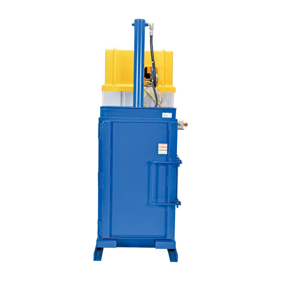
HDC-905 Series Hydraulic Drum Crushers
Receiving instructions:
After delivery, IMMEDIATELY remove the packaging from the product. Then, inspect the unit closely to determine
whether it sustained damage during transport. If damage is discovered, immediately record a complete
description of the damage on the bill of lading. If the product is undamaged, discard the packaging.
Notes:
1) Compliance with laws, regulations, codes, and non-voluntary standards enforced in the location where the product
is used is exclusively the responsibility of the owner/end-user.
2) VESTIL is not liable for any injury or property damage that occurs as a consequence of failing to apply either:
a) Instructions in this manual; or b) information provided on product labels.
Table of Contents:
Signal Words.......................................................................................................................................... 2
Safe Use Recommendations...................................................................................................................... 2
Hydraulic circuit diagram.......................................................................................................................... 3
Specifications......................................................................................................................................... 3
FIG. 1: HDC-905-IDC exploded parts diagram & bill of materials....................................................................... 4
FIG. 2: HDC-905-HC exploded parts diagram & bill of materials....................................................................... 5
FIG. 3: Power unit exploded parts diagram & bill of materials............................................................................6
FIG. 4: Detailed parts breakdown of manifold assembly.................. ............................................................... 7
Manifold, pressure switches, and valves...................................................................................................... 8
Hydraulic valve and pressure switch adjustment procedure............................................................................. 9
Electrical controls sequence of operation................................................................................................... 10
Electrical system specifications................................................................................................................ 10
FIG. 9: Standard 3-phase electrical circuit diagram (22124024 rev. F).............................................................. 11
FIG. 10: 3-phase continuous run electrical circuit diagram (22124025 rev. C)..................................................... 12
FIG. 11: Single phase 115VAC electrical circuit diagram (22124026 rev. D).......................................................13
FIG. 12: Single phase 208/230VAC electrical circuit diagram (22124027 rev. E)................................................. 14
Installation........................................................................................................................................... 15
Loading the chamber.............................................................................................................................. 15
Operation............................................................................................................................................. 15
Platen configurations........................................................................................................................... ... 16
Maintenance........................................................................................................................................ 16
Labeling Diagram................................................................................................................................... 17
Limited Warranty (all units except "Wash down" model HDC-905-WD)............................................................... 18
Limited Warranty (HDC-905-WD only)....................................................................................................... 19
Copyright 2017 Vestil Manufacturing Corp.
Vestil Manufacturing Corp.
2999 North Wayne Street, P.O. Box 507, Angola, IN 46703
Telephone: (260) 665-7586 -or- Toll Free (800) 348-0868
www.vestilmfg.com
Instruction Manual
HDC-905-IDC
Fax: (260) 665-1339
e-mail:
info@vestil.com
HDC-905-HC
Page 1 of 19
HDC-905, MANUAL
Advertisement
Table of Contents

Subscribe to Our Youtube Channel
Related Manuals for Vestil HDC-905 Series


Summary of Contents for Vestil HDC-905 Series
-
Page 1: Table Of Contents
2) VESTIL is not liable for any injury or property damage that occurs as a consequence of failing to apply either: a) Instructions in this manual; or b) information provided on product labels. -
Page 2: Signal Words
Safe Use Recommendations: Vestil strives to identify foreseeable hazards associated with the use of its products. However, material handling is dangerous and no manual can address every conceivable risk. Ultimately, the most effective way to avoid injury is for the operator to exercise sound judgment whenever using this machine. -
Page 3: Hydraulic Circuit Diagram
5. Door interlock switch 6. 24V control circuit: ON/OFF switch, cycle start button, CRUCH/COMPACT selector switch; 2 pressure switches (high pressure for drum crushing; low pressure for compacting contents inside a drum. Copyright 2017 Vestil Manufacturing Corp. Page 3 of 19... - Page 4 Frame, casting 36116 ”-10 hex nut 33012 Flat washer, low carbon, zinc finish, ” HBOLT 0.7500- 22-514-054 Weldment, platen Hex bolt 10x4.5x1.75-N Flat washer, low carbon, USS, zinc- 33016 plated, ” Copyright 2017 Vestil Manufacturing Corp. Page 4 of 19...
- Page 5 Hex nut, zinc-plated, ”-11UNC 33016 plated, ” Bolt, HHCS, #5 zinc-plated, ”- 22-645-003 Actuator, bolt, limit switch 13312 11x2 ” 22-016-074 Bracket, shim 37036 Nylock nut, zinc-plated, ”-11 22-514-049 Weldment, base frame Copyright 2017 Vestil Manufacturing Corp. Page 5 of 19...
- Page 6 Bracket 11005 ”-20x1” hex bolt 33618 ” lock washer 36102 ” -20 hex nut 33004 ” flat washer ET2L-252 230V heater ET3L-504 460V heater 5406-P-06 Pipe plug OR-172-N70 O-ring 121201JY Spring Copyright 2017 Vestil Manufacturing Corp. Page 6 of 19...
- Page 7 25psi check valve 6400-10-10 Fitting 99-153-015 2-way valve 99-034-008 24VAC coil 6400-10-08-0 Fitting 2-154 O-ring 23209 ¼ in. – 20 x 1 ½ in. SHCS bolt 6400-16-12 Fitting 10/10/6802 Fitting 99-022-005 Pressure switch Copyright 2017 Vestil Manufacturing Corp. Page 7 of 19...
-
Page 8: Manifold, Pressure Switches, And Valves
Adjustment hex flats of relief valve Gauge port (UL Lower pressure GA); install switch (PS1) Relief valve 3,000psi pressure gauge FIG. 7: Left side view FIG. 8: Right side view Copyright 2017 Vestil Manufacturing Corp. Page 8 of 19... -
Page 9: Hydraulic Valve And Pressure Switch Adjustment Procedure
Remove the pressure gauges and reinstall the cap plugs in ports GA and UL GA. c. Tighten the set screws of the pressure switches PS! And PS2 to fix the positions of the knurled knobs. Copyright 2017 Vestil Manufacturing Corp. Page 9 of 19... -
Page 10: Electrical Controls Sequence Of Operation
1 & 7 2 & 8 3 & 9 4,5, & 6 Tie together with wire nut 4 & 7 Tie together 5 & 8 Tie together 6 & 9 Tie together Copyright 2017 Vestil Manufacturing Corp. Page 10 of 19... - Page 11 *All components shown with unit in normal starting position, i.e. ram fully raised and cabinet door open. 1TR is ICM Controls: part no. ICM1028; Delay-on-make set for 2 minutes. 1T is ACME part no. TB-81324; 150VA control transformer or equivalent. Copyright 2017 Vestil Manufacturing Corp. Page 11 of 19...
- Page 12 Reservoir: Sentinel 031815-SA2 Pump: 22-143-001 Special motor/pump adapter & coupling Manifold 040615-SA1 Oil filter assembly in tank: SLF212SO **When pressure exceeds 350PSI, switch is open to allow compression before ram rises. Copyright 2017 Vestil Manufacturing Corp. Page 12 of 19...
- Page 13 2 minutes. 1T is ACME part no. TB-81324; 150VA control transformer or equivalent. Manifold part no. 22-127-015. **When pressure exceeds 350PSI, switch is open to allow compression before ram rises. Copyright 2017 Vestil Manufacturing Corp. Page 13 of 19...
- Page 14 1TR is ICM Controls: part no. ICM1028; Delay-on-make set for 2 minutes. 1T is ACME part no. TB-81324; 150VA control transformer or equivalent. Manifold part no. 22-127-015. **When pressure exceeds 350PSI, switch is open to allow compression before ram rises. Copyright 2017 Vestil Manufacturing Corp. Page 14 of 19...
-
Page 15: Installation
To disengage the stop button, pull it out. Press the cycle start button again to retract the cylinder and returns the platen to the home position. The crusher is again ready for normal operation. Copyright 2017 Vestil Manufacturing Corp. Page 15 of 19... -
Page 16: Platen Configurations
Then, flush the reservoir with fresh hydraulic fluid before filling it. Install the drain plug and fill the reservoir with new hydraulic fluid. Only use ISO AW-32 hydraulic oil or its equal. Copyright 2017 Vestil Manufacturing Corp. Page 16 of 19... -
Page 17: Labeling Diagram
Rev. 2/21/2017 HDC-905, MANUAL Labeling diagram: The unit should always be labeled as shown in the diagrams below. Replace any label that is missing, incomplete, or not easily readable. Copyright 2017 Vestil Manufacturing Corp. Page 17 of 19... -
Page 18: Limited Warranty (All Units Except "Wash Down" Model Hdc-905-Wd)
(you) for warranty service. Who may request service? Only a warrantee may request service. You are a warrantee if you purchased the product from Vestil or from an authorized distributor AND Vestil has been fully paid. -
Page 19: Limited Warranty (Hdc-905-Wd Only)
(you) for warranty service. Who may request service? Only a warrantee may request service. You are a warrantee if you purchased the product from Vestil or from an authorized distributor AND Vestil has been fully paid. What is an “original part”? An original part is a part used to make the product as shipped to the warrantee.
Need help?
Do you have a question about the HDC-905 Series and is the answer not in the manual?
Questions and answers