Table of Contents
Advertisement
Quick Links
Advertisement
Table of Contents

Related Manuals for American Megatrends MegaPro


Summary of Contents for American Megatrends MegaPro
- Page 1 MegaPro Dual Pentium® Pro PCI ISA Motherboard User's Guide MAN–745 2/5/97...
- Page 2 Limited Warranty Buyer agrees if this product proves to be defective, that American Megatrends, Inc. is only obligated to replace or refund the purchase price of this product at American Megatrend's discretion according to the terms and conditions on the motherboard warranty card.
- Page 3 This manual describes the specifications and features of the MegaPro PCI motherboard. It explains how to assemble a system based on the MegaPro PCI motherboard and how to use the AMIBIOS that is specifically designed for this motherboard.
-
Page 4: Packing List
American Megatrends DMI Wizard software utility and the Server Management Software for Windows a Warranty Card, and the American Megatrends MegaPro PCI Pentium Pro Motherboard User's Guide. Do not use 16 MB x 36 64 MB SIMMs that have 36 chips per SIMM. -
Page 5: Hardware Installation
PCI expansion slots. ISA DMA or Bus Masters The MegaPro Pentium Pro PCI ISA motherboard conforms to the PCI Version 2.1 specification, if the PCI 2.1 Compliance option in Chipset Setup is set to Enabled. The Version 2.1 PCI specification requires a deterministic latency for PCI devices. -
Page 6: Server Management Software
The server management software for Windows NT only monitors the following hardware parameters: CPU ambient temperatures, system voltage levels, CPU heat sink and chassis fan operation, chassis intrusion, and memory failure reporting if ECC is enabled MegaPro Dual Pentium Pro PCI ISA Motherboard User’s Guide... - Page 7 VGA Specification The PCI VGA on the MegaPro motherboard is supported by the ATI 3D RAGE II 264GT PCI Graphics Controller chip. The PCI VGA features are: 2 MB SGRAM. This RAM cannot be upgraded, a VGA cable is included, and video drivers for Windows 95 and Windows NT will be provided.
- Page 8 This motherboard contains sensitive electronic components that can be easily damaged by static electricity. Follow the instructions carefully to ensure correct installation and to avoid static damage. MegaPro Dual Pentium Pro PCI ISA Motherboard User’s Guide SIMM Sockets 1.5" CPU Fan and Voltage Regulators 2"...
-
Page 9: Step 1 Unpack The Motherboard
Step 1 Unpack the Motherboard Step Inspect the cardboard carton for obvious damage. If damaged, call 770–246–8645. Leave the motherboard in its original packing. Perform all unpacking and installation procedures on a ground–connected anti–static mat. Wear an anti–static wristband grounded at the same point as the anti–static mat. -
Page 10: Avoid Static Electricity
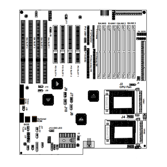
Make sure you stand on an anti–static mat when handling the motherboard. Avoid contact with any component or connector on any adapter card, printed circuit board, or memory module. Handle these components by the mounting bracket. MegaPro Dual Pentium Pro PCI ISA Motherboard User’s Guide... - Page 11 MegaPro Motherboard Layout P20 VGA Connector Megatrend Optional Megatren ds BIOS J13 IDE LED Pin 1 is identified by a square pin and by a pointed box on the silkscreen. Chapter 1 Hardware Installation KEBD BANK3 BANK0 BANK1 BANK2 P4 SER1...
-
Page 12: Step 2 Configure Cpu
Short Open Please contact American Megatrends technical support at 770–246–8645 to support a CPU running at a higher speed. MegaPro Dual Pentium Pro PCI ISA Motherboard User’s Guide Short Short Pins 1–2, Short Pins 1–2 Short Pins 3–4, Short Pins 5–6, Short Pins7–8... - Page 13 Step 2 Configure CPU, Continued CPU Voltage J4 and J5 set the CPU voltage. Each CPU can be independently set to the correct CPU core voltage. The factory setting for both CPUs is 3.3V. It should not be changed unless the CPU is rated differently. J4 sets the CPU voltage for the CPU in U14.
- Page 14 Step 2 Configure CPU, Continued Voltage Regulator One Voltage Regulator Module is shipped with every MegaPro motherboard. You need another VRM if you install two CPUs. Order VRMs for Intel Pentium Pro CPUs from: Manufacturer Part Number VXI Electronics, Inc.
- Page 15 Step 2 Configure CPU, Continued Install CPU Install the CPU in the ZIF socket by performing the following steps. The CPU sockets are near one edge of the motherboard. Warning Improper CPU installation can damage the CPU and the motherboard. You must follow the procedures in this section exactly as documented.
- Page 16 Step Complete installation by lifting the ZIF lever to the other side of the socket, as shown below. MegaPro Dual Pentium Pro PCI ISA Motherboard User’s Guide Action...
- Page 17 Step 3 Set Additional Jumpers J1 and J6 Power J1 and J6 select the 3.3V power source. J1 and J6 are 6–pin bergs. You can provide 3.3V power either: through the voltage regulator which is the default source, or from a 3.3V power supply. 3.3V From Voltage Regulator Set J1 and J6 as shown below to configure 3.3V power through the voltage regulator.
- Page 18 ATI VGA controller: Onboard PCI ATI VGA Interrupt Setting PCI interrupt enabled for onboard PCI ATI VGA Controller PCI interrupt disabled for onboard PCI ATI VGA Controller MegaPro Dual Pentium Pro PCI ISA Motherboard User’s Guide Continued Description Fan Sense Ground +12V...
- Page 19 Step 3 Set Additional Jumpers, J22 Server Management SMI J22 is a 2–pin berg that enables the server management SMI. The J22 settings are: Server Management SMI Setting Server management SMI is disabled. Server management SMI is enabled. J25 External SMI Switch J25 is a 2–pin berg that can be connected to a switch to generate an external SMI.
-
Page 20: Step 4 Install Memory
Bank0, then the same type of 4 MB SIMM must be installed in the second Bank0 SIMM socket. The minimum amount of system memory supported by the MegaPro PCI is 8 MB. Each socket can hold one SIMM. Use:... - Page 21 Step 4 Install Memory, Continued Select SIMMs Fast Page Mode SIMMs must meet the following specifications. EDO and Burst EDO SIMMs can also be installed on the MegaPro motherboard. Parameter Page Mode Refresh SIMM Part Numbers Type Manufacturer 1 MB x 36 Micron “...
- Page 22 Simple Maureen 800–367–7330 Technology Blando ext 240 Inc. Samsung All–American See your local Semiconductor sales rep. Bell Industries MegaPro Dual Pentium Pro PCI ISA Motherboard User’s Guide Part Number 714–453–8158 A1636–16XT–66T 714–851–2758 STI3616100A–60T See your local KMM53616000AK–6T sales rep. Cont’d...
- Page 23 Step 4 Install Memory, Continued Installing SIMMs Install 1 MB x 32 or 36, 2 MB x 32 or 36, 4 MB x 32 or 36, 8 MB x 32 or 36, or 16 MB x 32 or 36 SIMMs in the eight SIMM sockets. Do not use 16 MB x 36 64 MB SIMMs that have 36 chips per SIMM.
-
Page 24: Step 5 Install The Motherboard
If using metallic screws, make sure the head of the screw fits completely inside the plated mounting holes. See the graphic on the following screen. MegaPro Dual Pentium Pro PCI ISA Motherboard User’s Guide Action Warning Cont’d... -
Page 25: Step 5 Install Motherboard
Step 5 Install Motherboard, The screw head must not be larger than the plating around the mounting hole. Chapter 1 Hardware Installation Continued Plating... -
Page 26: Step 6 Attach Cables
LED. All motherboard components are outlined by a white rectangular box with a broad arrow at one end. Pin 1 is always at the arrow end of the white outlined box, as shown below: MegaPro Dual Pentium Pro PCI ISA Motherboard User’s Guide Cont’d... - Page 27 An additional 8A on +5V is required for each Pentium Pro CPU that is installed. If both Pentium Pro CPUs are installed on the MegaPro motherboard, the CPUs alone require 16 A on +5V. Add the power required by each adapter card that is installed.
- Page 28 The six–pin connector on the power cable with three red wires and two black wires is attached to P7. The other connector on the end of the power cable is attached to P6. MegaPro Dual Pentium Pro PCI ISA Motherboard User’s Guide Cont’d...
- Page 29 Step 6 Attach Cables, Continued Power Connector Keys The power connectors are keyed to prevent incorrect installation. The keys on the connector must be cut to fit on some power supplies, as shown below. Pin 1 P in 1 P6 Pinout Power Good Red wire +12 Volts...
- Page 30 P1 Pinout P1 is an auxiliary 5V power connector. P2 Pinout P1 provides 3.3V power. P3 Pinout P3 prov i des 3.3V power. MegaPro Dual Pentium Pro PCI ISA Motherboard User’s Guide Description Red wire Red wire Red wire Ground...
- Page 31 Step 6 Attach Cables, Continued P9 Keyboard Connector The keyboard connector is a 6–pin DIN socket. The pinout is shown below. 3, 6 Connect Mouse Cable P8 is the mouse connector. P8 is a 10–pin berg. The mouse cable is the same as the serial cable in the motherboard.
- Page 32 AMIBIOS signals hardware problems through the speaker. Pin 1 on the motherboard is identified by the arrow on the white box around the berg. MegaPro Dual Pentium Pro PCI ISA Motherboard User’s Guide Description Data Out...
- Page 33 Step 6 Attach Cables, Continued J23 Keyboard Lock J23 is a 5–pin single–inline berg that is attached via a cable to the keyboard lock connector or separate keyboard lock and Power LED connectors. The computer chassis may not include the keyboard lock and Power LED on a single connector.
- Page 34 AMIBIOS minimizes conflicts between onboard and offboard I/O devices. AMIBIOS automatically checks the adapter cards installed in the expansion slots on the MegaPro PCI motherboard for a hard disk or floppy controller and serial or parallel ports. P4 SER1 P5 SER2 P4 and P5 are 9–pin connectors that provide an AT–compatible serial...
- Page 35 Step 6 Attach Cables, Continued P12 Parallel Port P12 is a 25–pin connector for a parallel port. The pinout is below. All parallel port settings must be configured in Peripheral Setup in WINBIOS Setup. Connect the 16–pin to DB25 cable provided with the motherboard to P12.
-
Page 36: Vga Cable
The following drawing illustrates the VGA connectors on the VGA cable and the motherboard : motherboard plug ge d P in 1 4 is cu t MegaPro Dual Pentium Pro PCI ISA Motherboard User’s Guide Signal Description Ground Ground Ground... - Page 37 Step 6 Attach Cables, Continued Standard VGA Connector The pinout for the standard female DB15 VGA connector is shown below: Pin 6 Ground Pin 1 Red Pin 7 Ground Pin 2 G reen Pin 8 Grou nd Pin 3 Blue Pin 9 Fuse Pin 4 Pin 5 Ground...
- Page 38 34–pin ribbon connector with two 34–pin edge connectors for attaching the floppy disk drives. There is a small twist in the cable between the floppy connectors. The last connector should be connected to floppy drive A:. MegaPro Dual Pentium Pro PCI ISA Motherboard User’s Guide Cont’d...
- Page 39 Step 6 Attach Cables, Continued P10 Floppy Connector Pinout Twist in Floppy Cable Floppy B to A Floppy B to A 10 to 16 12 to 14 11 to 15 13 to 13 Chapter 1 Hardware Installation DENSE1 DRATE0 –INDEX –MOTOR0 –FDSEL1 –FDSEL0...
- Page 40 Step 6 Attach Cables, Continued IDE Drives Attach the IDE drives in the following manner. Choose Peripheral Setup in WINBIOS Setup to enable the onboard IDE controller. MegaPro Dual Pentium Pro PCI ISA Motherboard User’s Guide Cont’d...
- Page 41 Step 6 Attach Cables, Continued Attach IDE Cable to P11 P11 is the primary IDE hard disk drive connector. Both the primary master and the primary slave IDE drives must be connected by cable to P11, as shown below. P11 is a 40–pin dual–inline berg that connects an IDE drive to the primary onboard IDE connector.
- Page 42 IDE drives to the secondary onboard IDE controller. Attach the secondary master and slave IDE drives to P13 via a standard 40–pin IDE cable. MegaPro Dual Pentium Pro PCI ISA Motherboard User’s Guide DATA8 DATA9 DATA10...
- Page 43 Step 6 Attach Cables, Continued P13 Pinout The P13 pinou t is: –RESET DATA7 DATA6 DATA5 DATA4 DATA3 DATA2 DATA1 DATA0 –REQ –IOW –IOR IDERDY –ACK INT15 –CS2 Chapter 1 Hardware Installation DATA8 DATA9 DATA10 DATA11 DATA12 DATA13 DATA14 DATA15 Pullup –CS3...
-
Page 44: Step 7 Test And Configure
Run WINBIOS Setup. You must enter the requested information and save the configuration data in NVRAM. The system will then reset, run POST, and boot the operating system. See the following chapter for information on configuring the computer. MegaPro Dual Pentium Pro PCI ISA Motherboard User’s Guide... -
Page 45: Winbios Setup
Graphical Setup American Megatrends has a new type of system BIOS Setup utility. WINBIOS Setup has a graphical user interface the end user can access using a mouse. The WINBIOS Setup code is so compact that it can reside on the same ROM as the system BIOS. -
Page 46: Using A Mouse With Winbios Setup
Advance to the next screen. <Home> Returns to the beginning of the text. <End> Advance to the end of the text. <Ctrl><Alt><+> Change to high speed <Ctrl><Alt><–> Change to low speed. MegaPro Dual Pentium Pro PCI ISA Motherboard User’s Guide Action... -
Page 47: Winbios Setup Menu
WINBIOS Setup Menu The WINBIOS Setup main menu, shown below, is organized into four sections. Each of these sections corresponds to a section in this chapter. Each section contains several icons. Clicking on each icon activates a specific AMIBIOS function. The WINBIOS Setup main windows and related functions are described on the next screen. -
Page 48: Section 1 Setup
Move the cursor to these fields via and and select the floppy type. The settings are 360 KB 5¼ inch, 1.2 MB 5¼ inch, 720 KB 3½ inch, 1.44 MB 3½ inch, or 2.88 MB 3½ inch. MegaPro Dual Pentium Pro PCI ISA Motherboard User’s Guide... - Page 49 Standard Setup, Continued Pri Master, Pri Slave, Sec Master, Sec Slave Select one of these hard disk drive icons to configure the hard disk drive named in the option. Select Auto from the drive parameters screen to let AMIBIOS automatically configure the drive. A screen with a list of drive parameters appears.
- Page 50 Capacity The formatted capacity of the drive is the number of heads times the number of cylinders times the number of sectors per track times 512 bytes per sector. MegaPro Dual Pentium Pro PCI ISA Motherboard User’s Guide Description Cont’d...
-
Page 51: Hard Disk Drive Types
Standard Setup, Continued Hard Disk Drive Types Type Cylinders Heads Precompensation 1024 1024 1024 1024 1024 1024 1224 AMIBIOS automatically sets IDE drive parameters. Select USER to enter MFM, ESDI, or RLL drive parameters. Select Not Installed for SCSI drives. Select CDROM for CD–ROM drives. Chapter 2 WINBIOS Setup Write Landing... -
Page 52: Advanced Setup
Pins 2–3 of J15 on the motherboard must be shorted together to enable PS/2 mouse support . The settings are Enabled or Disabled. The Optimal and Fail–Safe default settings are Enabled. MegaPro Dual Pentium Pro PCI ISA Motherboard User’s Guide Cont’d... - Page 53 Advanced Setup, Continued Hit <DEL> Message Display Set this option to Disabled to prevent Hit <DEL> if you want to run Setup from appearing when the system boots. The settings are Enabled or Disabled. The Optimal and Fail–Safe default settings are Enabled. Wait for <F1>...
- Page 54 2nd Boot Device This option sets the sequence of boot drives for the second boot device. The settings are Disabled, Floppy, or CDROM. The Optimal and Fail–Safe default settings are Floppy. MegaPro Dual Pentium Pro PCI ISA Motherboard User’s Guide Cont’d...
- Page 55 Advanced Setup, Continued 3rd Boot Device This option sets the sequence of boot drives for the third boot device. The settings are Disabled or CDROM. The Optimal and Fail–Safe default settings are Disabled. 4th Boot Device This option sets the sequence of boot drives for the fourth boot device. The settings are Disabled or CDROM.
- Page 56 The contents of the video ROM area from C0000h – C7FFFh are copied from ROM to RAM for faster execution. The Optimal default setting is Cached. The Fail–Safe default setting is Disabled. MegaPro Dual Pentium Pro PCI ISA Motherboard User’s Guide Description Description Cont’d...
- Page 57 Advanced Setup, Continued Shadow C800,16K Shadow CC00,16K Shadow D000,16K Shadow D400,16K Shadow D800, 16K Shadow DC00,16K These options enable shadowing of the contents of the ROM area named in the option title. The ROM area that is not used by ISA adapter cards will be allocated to PCI adapter cards.
-
Page 58: Chipset Setup
The next time the error location is read, the chipset will once again find a bad bit. The chipset generates a Parity Error, indicating an uncorrectable memory error. The Optimal and Fail–Safe defaults are Disabled. MegaPro Dual Pentium Pro PCI ISA Motherboard User’s Guide Description then... Cont’d... - Page 59 Fail–Safe defaults are Disabled. Optional ROM The MegaPro PCI Pentium Pro motherboard has an empty option ROM socket near the ISA expansion slots. You can install a 32 KB ROM in this socket. The starting memory address of this ROM can be either C000h only if this computer does not have a VGA controller, C800h, D000h, or D800h.
- Page 60 CPU type and frequency. The settings are 1 Sysclock, 2 Sysclocks, 3 Sysclocks, 4 Sysclocks, 5 Sysclocks, 6 Sysclocks, 7 Sysclocks, 8 Sysclocks, or Disabled. The Optimal and Fail–Safe default settings are Disabled. MegaPro Dual Pentium Pro PCI ISA Motherboard User’s Guide Cont’d...
- Page 61 Chipset Setup, Continued ISA 16 Bit I/O Recovery This option specifies the length of the delay that is added to the CPU cycle between consecutive 16–bit I/O operations. The length of the delay is related to the CPU type and frequency. The settings are 1 Sysclock, 2 Sysclocks, 3 Sysclocks, 4 Sysclocks, or Disabled.
-
Page 62: Power Management Setup
The settings are Megakey the power savings state determined by the Megakey keyboard controller, Standby, Suspend or Disabled. The Optimal and Fail–Safe default settings are Disabled. MegaPro Dual Pentium Pro PCI ISA Motherboard User’s Guide Cont’d... - Page 63 Power Management Setup, DPMS Video Power Down Mode This option specifies the power state that a DPMS–compliant video subsystem enters when AMIBIOS places it in a power saving state after the specified period of display inactivity has expired. The settings are Standby, Suspend or Disabled.
- Page 64 CPU clock speed and the CPU clock speed when the computer is in the power–conserving state. The settings are 1:1, 1:2, 1:4, 1:8, 1:16, 1:32, 1:64, or 1:128. The Optimal and Fail–Safe default settings are 1:8. MegaPro Dual Pentium Pro PCI ISA Motherboard User’s Guide Continued Cont’d...
- Page 65 Power Management Setup, IRQ3 IRQ4 IRQ5 IRQ7 IRQ9 IRQ10 IRQ11 IRQ12 IRQ15 When set to Monitor, these options enable event monitoring on the specified hardware interrupt request line. If set to Monitor and the computer is in a power saving state, AMIBIOS watches for activity on the specified IRQ line.
- Page 66 Allocate IRQ to PCI VGA Set this option to Yes to allocate an IRQ to the PCI VGA controller. The settings are No or Yes. The Optimal and Fail–Safe default settings are MegaPro Dual Pentium Pro PCI ISA Motherboard User’s Guide Action Cont’d...
- Page 67 PCI/PnP Setup, Continued PCI Slot–1 Latency Timer PCI Slot–2 Latency Timer PCI Slot–3 Latency Timer PCI Slot–4 Latency Timer USB Device Latency Timer These options specify the latency timings in PCI clocks for USB devices and PCI devices installed in the PCI expansion slots. The settings are 32, 64, 96, 128, 160, 192, 224, or 248.
- Page 68 PCI IDE, IRQ9 will still be available for PCI and PnP devices, because at least one IRQ must be available for PCI and PnP devices. The settings are ISA or PCI/PnP. The Optimal and Fail–Safe default settings are PCI/PnP. MegaPro Dual Pentium Pro PCI ISA Motherboard User’s Guide Cont’d...
- Page 69 PCI/PnP Setup, Continued DMA Channel 0 DMA Channel 1 DMA Channel 3 DMA Channel 5 DMA Channel 6 DMA Channel 7 These options allow you to specify the bus type used by each DMA channel. The settings are PnP or ISA. The Optimal and Fail–Safe default settings are PnP.
-
Page 70: Peripheral Setup
This option enables the prefetch feature for the specified IDE device attached to the onboard Secondary IDE controller. The settings are Master, Slave, Both, or Disabled. The Optimal and Fail–Safe default settings are Disabled. MegaPro Dual Pentium Pro PCI ISA Motherboard User’s Guide Cont’d... - Page 71 Peripheral Setup, Continued Offboard PCI/ISA IDE Card This option specifies the expansion slot that the offboard PCI or ISA IDE Controller adapter card is installed in. The Onboard Primary/Secondary IDE option must be set to Disabled if this option is set to any value except Disabled.
- Page 72 This option specifies the IRQ used by the parallel port. The settings are Disabled, IRQ 5, or IRQ 7. The Optimal default setting is IRQ 7. The Fail–Safe default setting is Disabled. MegaPro Dual Pentium Pro PCI ISA Motherboard User’s Guide Caution Caution...
- Page 73 Peripheral Setup, Continued Parallel Port Address This option specifies the base I/O port address for the parallel port. The settings are 378h, 278h, or Disabled. The Optimal default setting is 378h. The Fail–Safe default setting is not provided. Parallel Port Mode This option specifies the parallel port mode.
-
Page 74: Section 2 Security
The Supervisor and User icons activate two different levels of password security: Supervisor and User. In addition, the computer can be configured so that all users must enter a password every time the system boots or when WINBIOS Setup is executed. MegaPro Dual Pentium Pro PCI ISA Motherboard User’s Guide... -
Page 75: Setting A Password
Setting a Password The password check option is enabled in Advanced Setup by choosing either Always the password prompt appears every time the system is powered on or Setup the password prompt appears only when WINBIOS Setup is executed. The password is encrypted and stored in NVRAM. -
Page 76: Changing A Password
Remember the Password Keep a record of the new password when the password is changed. If you forget the password, you must erase the system configuration information in NVRAM. MegaPro Dual Pentium Pro PCI ISA Motherboard User’s Guide... -
Page 77: Section 3 Utility
Section 3 Utility The icons in this section of the WINBIOS Setup main screen permit you to display WINBIOS Setup text displayed on the screen in a different language and to detect IDE hard disk drive parameters. If you choose to display the WINBIOS Setup screen text in a different language, the text for the screen messages written in the selected language must have been incorporated into the WINBOIS Setup code in AMIBIOS when the BIOS was manufactured. -
Page 78: Section 4 Default
Setup main menu. The Fail–Safe settings provide far from optimal system performance, but are the most stable settings. Use this option as a diagnostic aid if the system is behaving erratically. MegaPro Dual Pentium Pro PCI ISA Motherboard User’s Guide... -
Page 79: Programming Flash Rom
Programming Flash ROM All versions of the MegaPro PCI motherboard use Flash EPROM to store the system BIOS. The advantage of Flash EPROM is the EPROM chip does not have to be replaced to update the BIOS. The end user can actually reprogram the BIOS, using a ROM file supplied by American Megatrends. - Page 80 S745P.ROM resides on a floppy disk and contains the updated main BIOS code. American Megatrends will provide this file when the AMIBIOS for the MegaPro PCI ISA motherboard must be updated. S745P.ROM must be present in the root directory of the floppy disk before the onboard Flash EPROM can be reprogrammed.
- Page 81 Programming the Flash ROM, Beep Codes The bootblock code produces a series of beeps during Flash ROM programming to: signify completion of a step as shown on the previous screen or to signal an error. Error beeps are arranged in a coded sequence and have different meanings depending on when they occur.
-
Page 82: Bootblock Code Checkpoint Codes
Flash ROM. Detect the flash type. Start erasing flash blocks. Program the Flash ROM in the E0000–EFFFFh region. Start programming Flash at F0000–FFFFF region. Flash programming is successful. The computer reboots. MegaPro Dual Pentium Pro PCI ISA Motherboard User’s Guide Description... -
Page 83: Deleting A Password
Deleting a Password If you forget the passwords you set up through WINBIOS Setup, the only way you can restart the computer is to erase the system configuration information where the passwords are stored. System configuration data is stored in CMOS RAM, a type of memory that consumes very little power. - Page 84 Make sure you stand on an anti–static mat when handling the motherboard. Avoid contact with any component or connector on any adapter card, printed circuit board, or memory module. Handle these components by the mounting bracket. MegaPro Dual Pentium Pro PCI ISA Motherboard User’s Guide...
-
Page 85: Engineering Specifications
A Specifications Engineering Specifications Temperature Ranges The following values are ambient temperatures inside the computer case. The board temperatures reflect the dual Pentium Pro CPU Heat dissipation requirements because they will be the hottest motherboard components. Temperature specifications vary with the CPU frequency. Frequency Heat Airflow over...
Need help?
Do you have a question about the MegaPro and is the answer not in the manual?
Questions and answers