Table of Contents
Advertisement
Quick Links
Advertisement
Chapters
Table of Contents

Subscribe to Our Youtube Channel
Related Manuals for Weber mt TRC 66


Summary of Contents for Weber mt TRC 66
- Page 1 OPERATING AND MAINTENANCE INSTRUCTION MANUAL TRC 66 - 86 Lombardini Engine Weber Maschinentechnik GmbH LDW 1003 P. O. Box 21 53 D-57329 Bad Laasphe-Rückershausen Germany Phone +49 27 54 / 398-0 Fax +49 27 54 3 98-101 (Reception) and ++3 98-102 (Spare Parts)
- Page 2 TRC66-86 *** 2...
- Page 3 Preface These operating and maintenance instructions describe the safe operation of the TRC 66 and TRC 86 trench compactors. Please read this operation manual and familiarize yourself with all details of your trench compactor before operating the machine for the first time. Carefully follow all instructions and always carry out the described operations in the indicated order.
- Page 4 General Safety Instructions Designated Use Trench compactors are only allowed to be operated in accordance with their designated use, whereby the operating and maintenance instructions, the directives*, the generally accepted safety and traffic rules and the regulations of the individual countries of use must be followed.
-
Page 5: Table Of Contents
Table of Contents Paragr. Title Page Paragr. Title Page Technical Description ....2.9.2 Putting the Compactor out of Operation, Remote Control ..... 30 Illustration ..........6 1.1.1 Overall View ..........6 Maintenance ....... 1.1.2 Controls and Indicators ......8 1.1.3 Operating Elements of the Remote Safety Precautions for Maintenance Control ............ -
Page 6: Technical Description
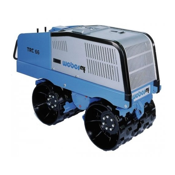
1 Technical Description 1.1 Illustration 1.1.1 Overall View Figure 1 Drums, R. H. Vibrator Tie-down lug, front Water cooler/hydraulic oil cooler Engine hood TRC66-86 *** 6... - Page 7 Figure 2 Hydraulic oil tank Drums, L. H. Scraper Hydraulic motors, rear (not shown) Tie-down lug Diesel engine (not shown) Control panel Hydraulic oil filter Lifting lug Anti-vandalism flap Hydraulic motor, vibration Deadman handle TRC66-86 *** 7...
-
Page 8: Controls And Indicators
1.1.2 Controls and Indicators Figure 3 Anti-vandalism flap Emergency stop switch Switch, vibration Switch, working speed/start Switch - manual operation/remote controlled operation Hood unlocking lever Pilot lamp, glow system Engine speed adjustment (idling, full speed) Electrical module Drive levers, manual operation Function control lamp Alternator charge warning light Low engine oil pressure indicator light... -
Page 9: Operating Elements Of The Remote Control
1.1.3 Operating Elements of the Remote Control Figure 4 Joystick, propulsion L. H. Joystick, propulsion R. H. / Start Light-emitting diode, function pilot lamp Light-emitting diode, accumulator charge Socket, charging cable Push button - full speed/idling Switch, engine start/stop Switch, high-speed range/vibration Figure 5 Figure 6 Receiver, radio remote control... -
Page 10: Ec Declaration Of Conformity For Radio Remote Control
(Translation) EC Declaration of Conformity for Radio Remote Control We herewith declare that the following device FA-9 is in compliance with the essential protection requirements of the Council Directive 89/336/EC on the approximation of the laws of the Member States relating to electromagnetic compatibility (EMC) (89/336/EEC). This declaration applies to all items produced. -
Page 11: Machine Description
1.2 Machine Description The trench compactors of the TRC 66 and TRC 86 series are used for the compaction of cohesive and heavy cohesive soils being excavated on site and used again as backfill material. Propulsion The propulsion unit, a water-cooled Lombardini diesel engine, type LDW 1003, drives three gear pumps, whereby one pump acts on the L.H. -
Page 12: Specifications
1.3 Specifications TRC 66 TRC 86 Weight Dead weight (in kg) 1340 1380 Operating weight CECE (in kg) 1350 1390 Average static linear load (front/rear) (N/cm) Dimensions Overall length (in mm) 1845 1845 Overall width (in mm) Height (in mm) - Page 13 TRC 66 TRC 86 Vibration central eccentric outside of the drum System hydraulic Type of drive Frequency (in Hz) 32/23 32/23 Centrifugal force (in kN) 75,2/45,2 75,5/45,5 manual/ manual/ Operation remote control remote control Noise and vibration measuring values* Sound pressure level LPA...
- Page 14 Please fill in the following data of your trench compactor: MADE IN ITALY 1 TYPE ......... 2 MACHINE NUMBER .......... 3 ENGINE TYPE ......... 4 ENGINE SERIAL NUMBER ........Rating Plate, Remote Control Frequency Serial No. Sending Module BZT* approved (* German Federal Office for Homologation in Telecommunications) TRC66-86 *** 14...
-
Page 15: Operation
2 Operation 2.1 Safety Precautions for the Operation Before every working shift, the operator of the compactor must check the operativeness of all controls and safety elements as well as the proper installation of all protection devices. The compactor is only allowed to be operated with all protection devices in place. -
Page 16: Transport
2.2 Transport Short distances on the job site can be covered by the compactor under its own power in accordance with paragraph 2.6.1. For transporting the compactor over long distances, the machine can be lifted on an appropriate transport vehicle (truck, trailer) by means of a crane. In addition, the compactor can be driven on a trailer suited for this purpose. -
Page 17: Commissioning
2.3 Commissioning Caution! During the first 50 operating hours, the engine must be operated at 70 % of its maximum load only. Commissioning requires normal pre-start work only. Keep to the initial maintenance intervals (refer to paragraph 3.2.1). 2.4 Pre-Start Work - Check the whole compactor for evident damage, eliminate visual damage. -
Page 18: Checking The Engine Oil Level
2.4.2 Checking the Engine Oil Level Caution! Always check the engine oil level with the compactor in horizontal position. - Open the hood lock (5/1). - Open the hood lock flap (5/2). Danger! Risk of scalds because of hot engine parts! Figure 5 - Pull out the oil dipstick (6/1), wipe the oil from the dipstick with a clean, non-fluffing cloth and insert... -
Page 19: Checking The Coolant Level
2.4.3 Checking the Coolant Level Danger! Only check the coolant level with the engine switched off and cooled down, otherwise risk of scalds because of hot steam. - Open the hood lock (9/1). - Open the hood lock flap (9/2). - Open the cover (10/1). -
Page 20: Checking The Hydraulic Oil Level
2.4.4 Checking the Hydraulic Oil Level Caution! Always check the hydraulic oil level with cold hydraulic oil and the compactor in the horizontal position. - Unlock the dashboard (11/1) by pulling up the lock (11/2). - Fold up the dashboard (11/1) and turn it on the engine console. -
Page 21: Checking The Deadman Switch
2.4.5.2 Checking the Deadman Switch - Start the compactor (refer to paragraph 2.5). - Reverse the compactor (refer to paragraph 2.6). - Actuate the deadman handle (15/1). The travel drive is switched off. The compactor and the vibration system must stop. - Move both drive levers (13/1) to the front. -
Page 22: Fitting The Remote Control Unit
2.4.7 Fitting the Radio Remote Control Unit - Pull up the hood lock (17/1) to unlock the dashboard (17/2). - Pull up the dashboard (17/2) and turn it on the engine console. Figure 17 - Fasten the receiver (18/1) by means of the rubber rings (18/2) provided for this purpose. - Page 23 - Put the sender (21/1) into the bracket (20/1). Figure 20 Figure 21 - Connect the receiver (22/1) to the charging cable (22/2) and to the sender (22/3). - Close the dashboard (17/2). Figure 22 TRC66-86 *** 23...
-
Page 24: Starting, Manual Operation
2.5 Starting - Manual Operation - Open the anti-vandalism flap (23/1). - Move the drive levers (24/1) to the vertical position. - Unlock the emergency stop switch (24/2). - Turn the "working speed" switch (24/3) to the "START" position. - Turn the switch (24/4) to the position. -
Page 25: Operation, Manual
2.6 Operation, Manual Danger ! When going uphill, the operator must always walk on the downhill side and, vice versa, when going downhill, the operator must always walk on the uphill side. Passengers are not allowed to ride on the compactor. Caution! During continuous duty, the maximum inclination the compactor may have is 25 %. -
Page 26: Steering
2.6.3 Steering The driving speeds and the curve radii are changed by the various drive lever movements. 2.6.3.1Turning a R. H. Curve - Push the L. H. drive lever (27/2) to the front, according to the desired curve radius. - Push the R. H. drive lever (27/1) less to the front, according to the desired curve radius. -
Page 27: Automatic Activation Of Vibration
2.6.4 Automatic Activation of Vibration Put the compactor into operation as described in paragraph 2.5/2.6 Starting/Operation. - Turn the switch (32/1) to the position. - Turn the switch (32/2) to the "Auto" position. - Push the levers (32/2) to the desired direction of travel. -
Page 28: Starting The Compactor By Remote Control
2.7 Starting the Compactor by Remote Control Danger ! The deadman handle/emergency stop switch override all other functions of the machine. If the deadman handle is actuated, the machine will automatically move forward 0.5 m and will then stop. The vibration system will be turned off. Before starting the compactor, ensure that nobody is in the danger area of the compactor and that all protective devices are properly in place. -
Page 29: Operation
2.8 Operation 2.8.1 Remote Controlled Operation Danger! Passengers are not allowed to ride on the compactor. Caution! During continous operation, the maximum inclination the compactor may have is 25 %. - Start the compactor as described in paragraph 2.5. - The engine is accelerated to full speed. - The driving speed/working speed/vibration is controlled by the lever (35/1). -
Page 30: Putting The Compactor Out Of
2.9 Putting the Compactor out of Operation Before work breaks and at the end of every day's shift, the compactor must be parked on a stable base which should be as horizontal as possible. If the machine is parked on a slope, use wedge-shaped brake blocks to prevent any unintentional movement of the compactor. -
Page 31: Maintenance
3 Maintenance 3.1 Safety Precautions for Maintenance Work Depending on the operating conditions, compactors must be made subject to an expert's check for operational safety as required, but at least once a year. The inspection results must be recorded in writing and kept at least until the next inspection. -
Page 32: Maintenance Survey
3.2 Maintenance Survey Any maintenance work which must be performed on the compactor is listed in two charts. The first chart (paragraph 3.2.1) indicates the initial maintenance work which has to be carried out once at a certain time after commissioning. The routine maintenance work indicated in the second chart (paragraph 3.2.2) has to be repeated at regular intervals. -
Page 33: Routine Maintenance
3.2.2 Routine Maintenance Maintenance Maintenance Maintenance Work Remarks Interval Point Every 8 operating Whole compactor Check for visible damage, leaks etc. hours Check controls and 2.4.5 Controls safety devices for proper functioning Hydraulic system Check the fittings and hoses for tightness, if necessary retighten fittings and replace defective hoses... - Page 34 Maintenance Maintenance Maintenance Remarks Interval Point Work Every 500 operating Engine hours Fan V-belt Replace 3.3.9 Valves Check the valve Manual of the clearance, adjust if engine necessary manufacturer Vibrator Change the oil 3.3.7 Change the hydraulic 3.3.6 Hydraulic system Hydraulic system Replace the hydraulic 3.3.5...
-
Page 35: Description Of The Maintenance Work
3.3 Description of the Maintenance Work 3.3.1 Changing the Engine Oil - Put the compactor out of operation as described in paragraph 2.9. Caution! Drain the engine oil at working temperature only. - Remove the fastening screws (1/1) on both sides of the engine hood (1/2). -
Page 36: Replacing The Engine Oil Filter
Important! The drain screw (4/1) is on the right side of the central frame. - Screw the oil drain tube (5/1) down to the oil drain valve (5/ As soon as the oil drain hose is fully screwed down, the used oil will escape. Danger! Danger of scalds because of hot oil. -
Page 37: Cleaning/Replacing The Air Filter Cartridge
3.3.3 Cleaning/Replacing the Air Filter Cartridge Important! The air filter cartridge needs to be cleaned/replaced only when the air filter service indicator light goes - Put the compactor out of operation as described in paragraph 2.9. - Open the maintenance door (8/1). - Loosen the clamps (9/1) and remove the cover (10/1) Figure 8 from the air filter body. -
Page 38: Replacing The Fuel Filter
3.3.4 Replacing the Fuel Filter Danger! This work is allowed with cold engine only. - Open the engine hood as described in paragraph 3.3.1. - Have an appropriate pan at hand. - Turn the fuel filter (12/1) - by hand or by means of an appriopriate tool - in counterclockwise direction to unscrew the filter. -
Page 39: Replacing The Hydraulic Oil Filter
3.3.5 Replacing the Hydraulic Oil Filter - Put the compactor out of operation as described in paragraph 2.9. - Undo the four screws and remove the protection hood (13/1) of the hydraulic oil filter (14/1). - Unscrew the cover (14/2) of the hydraulic oil filter (14/1). - Take out the filter element (15/1) and replace it by a new filter element. -
Page 40: Changing The Hydraulic Oil
3.3.6 Changing the Hydraulic Oil - Put the compactor out of operation as described in paragraph 2.9. - Open the engine hood as described in paragraph 3.3.1. Caution! Change the hydraulic oil at operating temperature only. - Open the cap (14/2) of the hydraulic tank . - Have an appropriate drain pan at hand. -
Page 41: Changing The Vibrator Oil
3.3.7 Changing the Vibrator Oil - Put the compactor out of operation as described in paragraph 2.9. Caution! Change the vibrator oil at operating temperature and with the compactor in the horizontal position only. - Put an appropriate oil pan under the oil drain screw (17/1). -
Page 42: Checking And Retensioning The Fan V-Belt
3.3.8 Checking and Retensioning the Fan V- Belt - Put the compactor out of operation as described in paragraph 2.9. - Open the engine hood as described in paragraph 3.3.1. Any maintenance work in the engine compartment as well as opening the engine hood is allowed with the engine turned off only. -
Page 43: Consumables And Quantities
3.4 Consumables and Quantities Assembly Group Consumable Quantity Summer Winter TRC 66 TRC 86 Engine SAE 15W/40 (-10...+50 °C) 3.25 l 3.25 l Engine oil Oil quality SAE 20W/20 SAE 10W (-20...+10 API - CD (+5...+30 °C) °C) HD series 3... -
Page 44: Malfunctions During Operation
4 Malfunctions During Operation 4.1 General If a malfunction occurs on the trench compactor, proceed as follows: Put the trench compactor out of operation as described in paragraph 2.9. Determine the source of the malfunction (refer to paragraph 4.2 - Trouble Shooting). Eliminate the malfunction (refer to paragraph 4.3 (Maintenance and Repair Work). -
Page 45: Trouble Shooting
4.2 Trouble Shooting Failure Possible Cause Remedy Remarks Engine does not Operating error Start the machine start as described Lack of fuel Check the fuel level 2.4.1 Dirty fuel filter Change the fuel 3.3.4 filter Dirty air filter Clean the air filter, if required, replace 3.3.3 the air filter... -
Page 46: Repair And Replacement Work
4.3 Repair and Maintenance Work 4.3.1 Replacing the Battery - Put the compactor out of operation as described in paragraph 2.9. - Pull up the hood lock (1/2) and unlock the dashboard (1/1). - Pull up the dashboard (1/1) and turn it on the engine console. -
Page 47: Checking/Replacing The Fuses
4.3.2 Checking/Replacing the Fuses - Put the compactor out of operation as described in paragraph 2.8. - Pull up the hood lock (4/2) and unlock the dashboard (4/1). - Pull up the dashboard (4/1) and turn it on the engine console. - Remove the cover (5/1 and 6/1) from the fuse box (6/2). -
Page 48: Charging The Sender Accumulator With The Charger
4.3.3 Charging the Sender Accumulator with the Charger Important ! The accumulator has a nominal capacity of 600 mAh which provides enough energy for a continuous sending operation of approximately 12 to 15 hours. Important ! Figure 7 Whent the red pilot lamp (7/1) lights up and an acoustic signal is given, the battery must be charged immediately. -
Page 49: Charging The Sender Accumulator On The Machine
4.3.3.1 Charging the Sender Accumulator on the Machine Important ! The accumulator has a nominal capacity of approximately 600 mAh which provides enough energy for a continuous sending operation of approximately 12 to 15 hours. Important ! Figure 9 When the red pilot lamp (10/2) lights up and an acoustic signal is given, the battery must be charged immediately. -
Page 50: Venting The Fuel Line
4.3.3.2 Venting the Fuel Line - Put the compactor out of operation as described in paragraph 2.9. - Open the engine hood as described in paragraph 3.3.1. - Loosen the venting screw (12/1) of the fuel filter (12/2). - Operate the pump lever (13/1) to allow any air in the fuel line to escape through the venting screw (12/1). -
Page 51: Diagrams
5 Diagrams 5.1 Electric Diagram TRC66-86 *** 51... - Page 52 Electric Diagram Battery Starter Three-phase alternator with voltage controller EHB diesel engine control system with ignition start switch Terra remote control receiver, 9-channel Fuse, 50 Ampere: three-phase alternator Fuse, 20 Ampere: machine control, starter solenoid Fuse, 50 Ampere: glow plugs Fuse, 30 Ampere: engine speed adjustment solenoid Fuse, 15 Ampere: machine control, logic board Manometric oil switch...
-
Page 53: Hydraulic Diagram
5.2 Hydraulic Diagram TRC66-86 *** 53... - Page 54 Hydraulic Diagram Diesel engine LDW 1003 Triple gear pump Control block Pressure relief valves Directional control valve Directional control valve Pressure control valve Non-return valves Load control valve Directional control valves Change-over valve Return line filter Non-return valve Oil/water cooler Wheel hub motors with brake Wheel hub motors Gear motor...
-
Page 55: Machine Preservation
6 Machine Preservation If the trench compactor is planned to be put out of operation for an extended period of time (approx. 1 ... 6 months), e. g. during the winter season, it must be stored in a frost-proof and dry room. Prior to the storage of the machine, however, the preservation measures described in paragraph 6.1 must be taken. -
Page 56: Removing Machine Preservatives
6.2 Removing Machine Preservatives Assembly Group Measures Remarks - Thoroughly clean Whole compactor Battery - Install, charge if necessary # 4.3.1 Compactor - Perform pre-start work # 2.4. TRC66-86 *** 56... - Page 57 TRC66-86 *** 57...
-
Page 58: Addresses, Weber Maschinentechnik Gmbh
7 Addresses, Weber Maschinentechnik GmbH For problems, questions and further information refer to one of the following addresses: in Germany WEBER Maschinentechnik GmbH Telefon + 49 (0) 2754 - 398-0 Postfach 2153 Telefax + 49 (0) 2754 - 398101-switchboard 57329 Bad Laasphe - Rückershausen + 49 (0) 2754 - 398102- spare parts- directlinie E-Mail... - Page 59 TRC66-86 *** 59...
- Page 60 > Vibratory Plate Compactors > Vibratory Tampers > Vibratory Rollers > Joint Cutters > Poker Vibrators and Converters > Rotary Trowels Weber MASCHINENTECHNIK GmbH Im Boden 57334 Bad Laasphe - Rückershausen Postfach 2153 57329 Bad Laasphe Telefon 027 54 / 398 0 - Telefax 027 54 / 398 101 TRC66-86 *** 60...
Need help?
Do you have a question about the TRC 66 and is the answer not in the manual?
Questions and answers