
Related Manuals for ASROCK WRX80D8-2T/X550


Summary of Contents for ASROCK WRX80D8-2T/X550
- Page 1 WRX80D8-2T WRX80D8-NL WRX80D8-2T/X550 User Manual Version 1.0 Published February 2022 Copyright©2022 ASRock Rack INC. All rights reserved.
- Page 2 In no event shall ASRock Rack, its directors, officers, employees, or agents be liable for any indirect, special, incidental, or consequential damages (including damages for loss of profits, loss of business, loss of data, interruption of business and the like), even if ASRock Rack has been advised of the possibility of such damages arising from any defect or error in the documentation or product.
- Page 3 ASRock Rack follows the green design concept to design and manufacture our products, and makes sure that each stage of the product life cycle of ASRock Rack product is in line with global environmental regulations. In addition, ASRock Rack disclose the relevant information based on regulation requirements.
-
Page 4: Table Of Contents
Contents Chapter 1 Introduction Package Contents Specifications Unique Features Motherboard Layout Onboard LED Indicators I/O Panel Block Diagram Chapter 2 Installation Screw Holes Pre-installation Precautions Installing the CPU and Heatsink Installing the CPU Cooler Installation of Memory Modules (DIMM) Expansion Slots (PCI Express Slots) Onboard Headers and Connectors Dr. - Page 5 Main Screen Advanced Screen 3.3.1 OC Tweaker (for the AMD Ryzen™ Threadripper™ PRO 5000WX series CPU only) 3.3.2 CPU Configuration 3.3.3 Chipset Configuration 3.3.4 Storage Configuration 3.3.5 NVME Configuration 3.3.6 ACPI Configuration 3.3.7 Super IO Configuration 3.3.8 Serial Port Console Redirection 3.3.9 H/W Monitor 3.3.10 USB Configuration 3.3.11 PCI Subsystem Settings...
- Page 6 Server Mgmt 3.5.1 BMC Network Configuration 3.5.2 System Event Log 3.5.3 Bmc Self Test Log 3.5.4 View System Event Log 3.5.5 BMC Tools Event Logs Boot Screen 3.7.1 CSM Parameters Exit Screen Chapter 4 Software Support Download and Install Operating System Download and Install Software Drivers Contact Information Chapter 5 Troubleshooting...
-
Page 7: Chapter 1 Introduction
In case any modifications of this manual occur, the updated version will be available on ASRock Rack website without further notice. You may find the latest memory and CPU support lists on ASRock Rack website as well. ASRock Rack’s Website: www.ASRockRack.com If you require technical support related to this motherboard, please visit our website for specific information about the model you are using. -
Page 8: Specifications
1.2 Specifications WRX80D8-2T / WRX80D8-NL / WRX80D8-2T/X550 MB Physical Status Form Factor Dimension 12'' x 9.6'' (30.5 cm x 24.4 cm) Processor System Supports AMD Ryzen™ Threadripper™ PRO 3000WX Supports AMD Ryzen™ Threadripper™ PRO 5000WX Socket Single Socket SP3 (LGA4094) - Page 9 WRX80D8-2T WRX80D8-NL WRX80D8-2T/X550 Ethernet WRX80D8-2T / WRX80D8-2T/X550: Interface 10Gbps/1000 Mbps WRX80D8-NL: WRX80D8-2T: LAN Controller - 2 x RJ45 10GbpE by Intel® X710-AT2 - 1 x RJ45 Dedicated IPMI LAN port by RTL8211E - Supports Wake-On-LAN - Supports Energy Efficient Ethernet 802.3az...
- Page 10 80 Debug Port Fan Fail LED BMC heartbeat System BIOS BIOS Type AMI 256 Mb SPI Flash ROM BIOS Features - Plug and Play (PnP) - ACPI 2.0 Compliance Wake Up Events - SMBIOS 2.8.0 Support - ASRock Rack Instant Flash...
- Page 11 WRX80D8-2T WRX80D8-NL WRX80D8-2T/X550 Hardware Monitor Temperature - CPU Temperature Sensing - DRAM Temperature Sensing - MB Temperature Sensing - Card Side Temperature Sensing - Chipset Temperature Sensing - CPU/Rear/Front Fan Tachometer - CPU Quiet Fan (Allow Chassis Fan Speed Auto-Adjust by...
-
Page 12: Unique Features
. With this utility, you can press the <F6> key during the POST or the <F2> key to enter into the BIOS setup menu to access ASRock Rack Instant Flash. Just launch this tool and save the new BIOS file to your USB flash drive, floppy disk or hard drive, then you can update your BIOS only in a few clicks without preparing an additional floppy diskette or other complicated flash utility. -
Page 13: Motherboard Layout
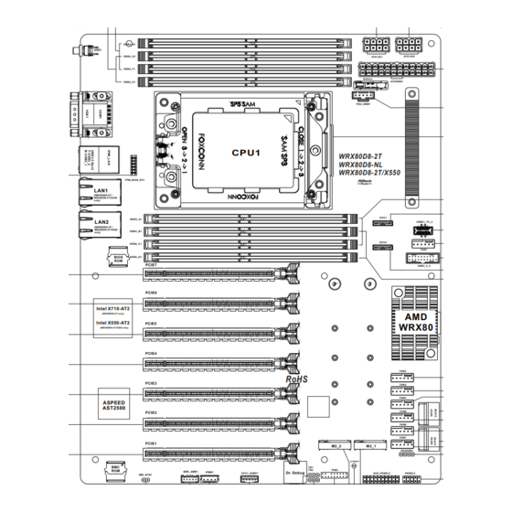
(WRX80D8-2T / WRX80D8-2T/X550 DDR4_B1 only) OCU2 DDR4_C1 FAN1 BIOS DDR4_D1 PCIE7 USB3_3_4 PCIE6 Intel X710-AT2 (WRX80D8-2T only) Intel X550-AT2 PCIE5 WRX80 (WRX80D8-2T/X550 only) PCIE4 FAN2 RoHS PCIE3 FAN3 FAN4 ASPEED AST2500 FAN5 PCIE2 FAN6 FAN7 PCIE1 M2_2 M2_1 PEAKER1 CLRMOS1... - Page 14 Description 2 x 288-pin DDR4 DIMM Slots (DDR4_E1, DDR4_G1) 2 x 288-pin DDR4 DIMM Slots (DDR4_F1, DDR4_H1) ATX 12V Power Connector (ATX12V1) ATX 12V Power Connector (ATX12V2) ATX Power Connector (ATXPWR1) PSU SMBus (PSU_SMB1) AMD Socket SP3 (LGA4094) 2 x 288-pin DDR4 DIMM Slots (DDR4_A1, DDR4_C1) OCuLink x4 Connector (OCU1) Type-C USB 3.2 Gen2x2 Header (USB31_TC_2) System Fan Connector (FAN1)
- Page 15 WRX80D8-2T WRX80D8-NL WRX80D8-2T/X550 Description BMC SMBus Header (BMC_SMB1) Non Maskable Interrupt Button (NMI_BTN1) PCI Express 4.0 x16 Slot (PCIE1) PCI Express 4.0 x16 Slot (PCIE2) PCI Express 4.0 x16 Slot (PCIE3) PCI Express 4.0 x16 Slot (PCIE4) PCI Express 4.0 x16 Slot (PCIE5) PCI Express 4.0 x16 Slot (PCIE6)
-
Page 16: Onboard Led Indicators
1.5 Onboard LED Indicators Status Description FAN1 failed FAN2 failed FAN3 failed FAN4 failed FAN5 failed FAN6 failed FAN7 failed Green STB PWR ready Green BMC heartbeat LED... -
Page 17: I/O Panel
No. Description UID Switch (UID1) LAN RJ-45 Port (IPMI_LAN)** LAN RJ-45 Port (LAN1)* VGA Port (VGA1) (WRX80D8-2T / WRX80D8-2T/X550 only) LAN RJ-45 Port (LAN2)* Serial Port (COM1) (WRX80D8-2T / WRX80D8-2T/X550 only) USB 3.2 Gen2 Type-A Ports (USB3_1_2) LAN Port LED Indications *There are two LED next to the LAN port. - Page 18 **There are two LEDs on each LAN port. Please refer to the table below for the LAN port LED indications. ACT/LINK LED SPEED LED LAN Port 10G LAN Port (LAN1, LAN2) LED Indications (WRX80D8-2T / WRX80D8-2T/X550 only) Activity / Link LED Speed LED Status Description No Link...
-
Page 19: Block Diagram
WRX80D8-2T WRX80D8-NL WRX80D8-2T/X550 1.7 Block Diagram WRX80D8-2T... - Page 20 WRX80D8-NL...
- Page 21 WRX80D8-2T WRX80D8-NL WRX80D8-2T/X550 WRX80D8-2T /X550...
-
Page 22: Chapter 2 Installation
Chapter 2 Installation This is an ATX form factor (12” x 9.6”, 30.5 cm x 24.4 cm) motherboard. Before you install the motherboard, study the configuration of your chassis to ensure that the motherboard fits into it. Make sure to unplug the power cord before installing or removing the motherboard. Failure to do so may cause physical injuries to you and damages to motherboard components. -
Page 23: Pre-Installation Precautions
WRX80D8-2T WRX80D8-NL WRX80D8-2T/X550 2.2 Pre-installation Precautions Take note of the following precautions before you install motherboard components or change any motherboard settings. 1. Unplug the power cord from the wall socket before touching any components. 2. To avoid damaging the motherboard’s components due to static electricity, NEVER place your motherboard directly on the carpet or the like. -
Page 24: Installing The Cpu And Heatsink
2.3 Installing the CPU and Heatsink Unplug all power cables before installing the CPU. - Page 25 WRX80D8-2T WRX80D8-NL WRX80D8-2T/X550...
- Page 26 Carr ier Frame with CPU Rail Frame Please make sure that the carrier frame with CPU is closely attached to the rail frame while inserting it. Install the orange carrier frame with CPU. Don’t separate them.
- Page 27 WRX80D8-2T WRX80D8-NL WRX80D8-2T/X550...
-
Page 28: Installing The Cpu Cooler
2.4 Installing the CPU Cooler After you install the CPU into this motherboard, it is necessary to install a larger heatsink and cooling fan to dissipate heat. You also need to spray thermal grease between the CPU and the heatsink to improve heat dissipation. Make sure that the CPU and the heatsink are securely fastened and in good contact with each other. - Page 29 WRX80D8-2T WRX80D8-NL WRX80D8-2T/X550...
-
Page 31: Installation Of Memory Modules (Dimm)
WRX80D8-2T WRX80D8-NL WRX80D8-2T/X550 2.5 Installation of Memory Modules (DIMM) This motherboard provides eight 288-pin DDR4 (Double Data Rate 4) DIMM slots and supports Eight Channel Memory Technology. CPU1 1 DIMM 2 DIMMS 4 DIMMS 8 DIMMS 1. It is not allowed to install a DDR, DDR2 or DDR3 memory module into a DDR4 slot;... - Page 32 The DIMM only fits in one correct orientation. It will cause permanent damage to the motherboard and the DIMM if you force the DIMM into the slot at incorrect orientation.
-
Page 33: Expansion Slots (Pci Express Slots)
WRX80D8-2T WRX80D8-NL WRX80D8-2T/X550 2.6 Expansion Slots (PCI Express Slots) There are 7 PCI Express slots on this motherboard. PCIE slot: PCIE1~PCIE7 (PCIE 4.0 x16 slot, from CPU) are used for PCI Express x16 lane width graphics cards. Slot Generation Mechnical... -
Page 34: Onboard Headers And Connectors
2.7 Onboard Headers and Connectors Onboard headers and connectors are NOT jumpers. Do NOT place jumper caps over these headers and connectors. Placing jumper caps over the headers and connectors will cause permanent damage to the motherboard. System Panel Header C on nec t t he power sw itch, PLED+ PLED-... - Page 35 WRX80D8-2T WRX80D8-NL WRX80D8-2T/X550 Auxiliary Panel Header This header supports multiple (18-pin AUX_PANEL2) functions on the front panel, (see p.7, No. 25) including the front panel SMB, internet status indicator and chassis intrusion pin. A. Front panel SMBus connecting pin (6-1 pin FPSMB) This header allows you to connect SMBus (System Management Bus) equipment.
- Page 36 Front Panel Type C USB There is one Front 3.2 Gen2x2 Header Panel Type C USB (20-pin USB31_TC_2) 3.2 Gen2x2 Header (see p.7, No. 10) on this motherboard. This header is used for connecting a USB USB Type-C Cable 3.2 Gen2x2 module for additional USB 3.2 Gen2x2 ports.
- Page 37 WRX80D8-2T WRX80D8-NL WRX80D8-2T/X550 System Fan Connectors Please connect the fan cables to (6-pin FAN1) the fan connectors and match (see p.7, No. 11) the black wire to the ground 12V(FAN_VOLTAGE) (6-pin FAN2) pin. All fans supports Fan FAN_SPEED_SENSOR1 FAN_SPEED_CONTROL (see p.7, No. 15) Control.
- Page 38 ALERT PSU SMBus PSU SMBus monitors the SMBCLK (PSU_SMB1) status of the power supply, fan (see p.7, No. 6) and system temperature. SMBDATA Non Maskable Interrupt Please connect a NMI device Button Header to this header. (NMI_BTN1) CONTROL (see p.7, No. 35) IPMB_SDA Intelligent Platform This 4-pin connector is used...
- Page 39 WRX80D8-2T WRX80D8-NL WRX80D8-2T/X550 Clear CMOS Pad This allows you to clear the (CLRMOS1) data in CMOS. To clear CMOS, (see p.7, No. 27) take out the CMOS battery and short the Clear CMOS Pad. SPI TPM Header This connector supports SPI...
-
Page 40: Dr. Debug
2.8 Dr. Debug Dr. Debug is used to provide code information, which makes troubleshooting even easier. Please see the diagrams below for reading the Dr. Debug codes. Code Description 0x10 PEI_CORE_STARTED 0x11 PEI_CAR_CPU_INIT 0x15 PEI_CAR_NB_INIT 0x19 PEI_CAR_SB_INIT 0x31 PEI_MEMORY_INSTALLED 0x32 PEI_CPU_INIT 0x33 PEI_CPU_CACHE_INIT... - Page 41 WRX80D8-2T WRX80D8-NL WRX80D8-2T/X550 0x63 DXE_CPU_INIT 0x68 DXE_NB_HB_INIT 0x69 DXE_NB_INIT 0x6A DXE_NB_SMM_INIT 0x70 DXE_SB_INIT 0x71 DXE_SB_SMM_INIT 0x72 DXE_SB_DEVICES_INIT 0x78 DXE_ACPI_INIT 0x79 DXE_CSM_INIT 0x90 DXE_BDS_STARTED 0x91 DXE_BDS_CONNECT_DRIVERS 0x92 DXE_PCI_BUS_BEGIN 0x93 DXE_PCI_BUS_HPC_INIT 0x94 DXE_PCI_BUS_ENUM 0x95 DXE_PCI_BUS_REQUEST_RESOURCES 0x96 DXE_PCI_BUS_ASSIGN_RESOURCES 0x97 DXE_CON_OUT_CONNECT 0x98 DXE_CON_IN_CONNECT...
- Page 42 0x99 DXE_SIO_INIT 0x9A DXE_USB_BEGIN 0x9B DXE_USB_RESET 0x9C DXE_USB_DETECT 0x9D DXE_USB_ENABLE 0xA0 DXE_IDE_BEGIN 0xA1 DXE_IDE_RESET 0xA2 DXE_IDE_DETECT 0xA3 DXE_IDE_ENABLE 0xA4 DXE_SCSI_BEGIN 0xA5 DXE_SCSI_RESET 0xA6 DXE_SCSI_DETECT 0xA7 DXE_SCSI_ENABLE 0xA8 DXE_SETUP_VERIFYING_PASSWORD 0xA9 DXE_SETUP_START 0xAB DXE_SETUP_INPUT_WAIT 0xAD DXE_READY_TO_BOOT 0xAE DXE_LEGACY_BOOT...
- Page 43 WRX80D8-2T WRX80D8-NL WRX80D8-2T/X550 0xAF DXE_EXIT_BOOT_SERVICES 0xB0 RT_SET_VIRTUAL_ADDRESS_MAP_BEGIN 0xB1 RT_SET_VIRTUAL_ADDRESS_MAP_END 0xB2 DXE_LEGACY_OPROM_INIT 0xB3 DXE_RESET_SYSTEM 0xB4 DXE_USB_HOTPLUG 0xB5 DXE_PCI_BUS_HOTPLUG 0xB6 DXE_NVRAM_CLEANUP 0xB7 DXE_CONFIGURATION_RESET 0xF0 PEI_RECOVERY_AUTO 0xF1 PEI_RECOVERY_USER 0xF2 PEI_RECOVERY_STARTED 0xF3 PEI_RECOVERY_CAPSULE_FOUND 0xF4 PEI_RECOVERY_CAPSULE_LOADED 0xE0 PEI_S3_STARTED 0xE1 PEI_S3_BOOT_SCRIPT 0xE2 PEI_S3_VIDEO_REPOST...
- Page 44 0xE3 PEI_S3_OS_WAKE 0x50 PEI_MEMORY_INVALID_TYPE 0x53 PEI_MEMORY_NOT_DETECTED 0x55 PEI_MEMORY_NOT_INSTALLED 0x57 PEI_CPU_MISMATCH 0x58 PEI_CPU_SELF_TEST_FAILED 0x59 PEI_CPU_NO_MICROCODE 0x5A PEI_CPU_ERROR 0x5B PEI_RESET_NOT_AVAILABLE 0xD0 DXE_CPU_ERROR 0xD1 DXE_NB_ERROR 0xD2 DXE_SB_ERROR 0xD3 DXE_ARCH_PROTOCOL_NOT_AVAILABLE 0xD4 DXE_PCI_BUS_OUT_OF_RESOURCES 0xD5 DXE_LEGACY_OPROM_NO_SPACE 0xD6 DXE_NO_CON_OUT 0xD7 DXE_NO_CON_IN...
- Page 45 WRX80D8-2T WRX80D8-NL WRX80D8-2T/X550 0xD8 DXE_INVALID_PASSWORD 0xD9 DXE_BOOT_OPTION_LOAD_ERROR 0xDA DXE_BOOT_OPTION_FAILED 0xDB DXE_FLASH_UPDATE_FAILED 0xDC DXE_RESET_NOT_AVAILABLE 0xE8 PEI_MEMORY_S3_RESUME_FAILED 0xE9 PEI_S3_RESUME_PPI_NOT_FOUND 0xEA PEI_S3_BOOT_SCRIPT_ERROR 0xEB PEI_S3_OS_WAKE_ERROR...
-
Page 46: Unit Identification Purpose Led/Switch
2.9 Unit Identification purpose LED/Switch With the UID button, You are able to locate the server you’re working on from behind a rack of servers. Unit Identification When the UID button on the purpose LED/Switch front or rear panel is pressed, (UID1) the front/rear UID blue LED indicator will be turned on. -
Page 47: Ssd Module Installation Guide
WRX80D8-2T WRX80D8-NL WRX80D8-2T/X550 2.10 M.2 SSD Module Installation Guide The Hyper M.2 Socket (M2_1/M2_2, Key M) supports type 2230/2242/2260/2280/22110 M.2 PCI Express module up to Gen4 x4 (16Gb/s x4). Installing the M.2_SSD (NGFF) Module Step 1 Prepare a M.2 SSD module and the screw. - Page 48 Step 3 Move the standoff based on the module type and length. The standoff is placed at the nut location D by default. Skip Step 3 and 4 and go straight to Step 5 if you are going to use the default nut. Otherwise, release the standoff by hand.
- Page 49 WRX80D8-2T WRX80D8-NL WRX80D8-2T/X550 Step 6 Tighten the screw with a screwdriver to secure the module into place. Please do not overtighten the screw as this might damage the module. NUT2 NUT1...
-
Page 50: Chapter 3 Uefi Setup Utility
Chapter 3 UEFI Setup Utility 3.1 Introduction This section explains how to use the UEFI SETUP UTILITY to configure your system. The UEFI chip on the motherboard stores the UEFI SETUP UTILITY. You may run the UEFI SETUP UTILITY when you start up the computer. Please press <F2> or <Del> during the Power-On-Self-Test (POST) to enter the UEFI SETUP UTILITY;... -
Page 51: Navigation Keys
WRX80D8-2T WRX80D8-NL WRX80D8-2T/X550 3.1.2 Navigation Keys Please check the following table for the function description of each navigation key. Navigation Key(s) Function Description Moves cursor left or right to select Screens Moves cursor up or down to select items + / - To change option for the selected items <Tab>... -
Page 52: Main Screen
3.2 Main Screen Once you enter the UEFI SETUP UTILITY, the Main screen will appear and display the system overview. The Main screen provides system overview information and allows you to set the system time and date. Mother Board Information This displays the information of the motherboard, BIOS and platform. -
Page 53: Advanced Screen
WRX80D8-2T WRX80D8-NL WRX80D8-2T/X550 3.3 Advanced Screen In this section, you may set the configurations for the following items: OC Tweaker, CPU Configuration, Chipset Configuration, Storage Configuration, NVMe Configuration, ACPI Configuration, Super IO Configuration, Serial Port Console Redirection, H/W Monitor, USB Configuration, PCI Subsystem Settings, Driver Health, Network Stack Con- figuration, AMD Mem Configuration Status, Tls Auth Configuration, AMD PBS, AMD Overclocking, AMD CBS, iSCSI Configuration and Instant Flash. -
Page 54: Oc Tweaker
3.3.1 OC Tweaker (supported for the AMD Ryzen™ Threadripper™ PRO 5000WX series CPU only) CPU Frequency and Voltage(VID) Change If Manual, multiplier and voltgae will be set based on user selection. Final result is depend- ing on CPU’s capability. Bixby Spread Spectrum Enable/disable Bixby Spread Spectrum. - Page 55 WRX80D8-2T WRX80D8-NL WRX80D8-2T/X550 DRAM Information Browse the serila presence detect (SPD) for DDR4 modules. Voltage Mode [OC]: Larger range ciktage for overclocking. [Stable]: Smaller range voltage for stable system. VCCM Use this item to adjust VCCM voltage.
-
Page 56: Cpu Configuration
3.3.2 CPU Configuration SVM Mode Enable/disable CPU Virtualization. -
Page 57: Chipset Configuration
Onboard VGA Enable/Disable Onboard VGA. Onboard X710 LAN Onboard X550 LAN (WRX80D8-2T only) / (WRX80D8-2T/X550 only) Enable/Disable Onboard LAN. SPI/LPC/fTPM TPM switch To select. 0: AMD CPU fTPM. 1 - LPC TPM. 2 - SPI TPM PCIE Link Width This allows you to select PCIE Link Width. The default value is [x16]. - Page 58 OCU2 Mode Selection This allows you to configure OCU2 PCIE(x4)/OCU2_SATA(0-3) Mode. Onboard Debug Port LED Enable or disable the onboard Dr. Debug LED. Restore AC Power Loss Select the power state after a power failure. If [Power Off] is selected, the power will remain off when the power recovers.
-
Page 59: Storage Configuration
WRX80D8-2T WRX80D8-NL WRX80D8-2T/X550 3.3.4 Storage Configuration This page allows you to configure storage devices. -
Page 60: Nvme Configuration
3.3.5 NVME Configuration If there is a NVMe device installed on the motherboard, the NVMe Configuration page will display the relevant information of the NVMe device you are using. Please note that the information and items shown here may vary depending on the NVMe device you use. -
Page 61: Acpi Configuration
WRX80D8-2T WRX80D8-NL WRX80D8-2T/X550 3.3.6 ACPI Configuration PCIE Devices Power On Allow the system to be waked up by a PCIE device and enable wake on LAN. Ring-In Power On Use this item to enable or disable Ring-In signals to turn on the system from the power- soft-off mode. -
Page 62: Super Io Configuration
3.3.7 Super IO Configuration Serial Port 1 Configuration Use this item to set parameters of Serial Port 1 (COM1). Serial Port Use this item to enable or disable the serial port. Serial Port Address Use this item to select an optimal setting for Super IO device. SOL Configuration Use this item to set parameters of SOL. -
Page 63: Serial Port Console Redirection
WRX80D8-2T WRX80D8-NL WRX80D8-2T/X550 3.3.8 Serial Port Console Redirection COM1/SOL Console Redirection Use this option to enable or disable Console Redirection. If this item is set to Enabled, you can select a COM Port to be used for Console Redirection. Console Redirection Settings Use this option to configure Console Redirection Settings, and specify how your computer and the host computer to which you are connected exchange information. - Page 64 Bits Per Second Use this item to select the serial port transmission speed. The speed used in the host computer and the client computer must be the same. Long or noisy lines may require lower transmission speed. The options include [9600], [19200], [38400], [57600] and [115200]. Data Bits Use this item to set the data transmission size.
- Page 65 WRX80D8-2T WRX80D8-NL WRX80D8-2T/X550 Redirection COM Port Use this item to select a COM port to display redirection of Legacy OS and Legacy OPROM Messages. Resolution On Legacy OS, the Number of Rows and Columns supported redirection. Redirection After POST If the [Bootloader] is selected, legacy console redirection is disabled before booting to legacy OS.
- Page 66 CTS], and [Software Xon/Xoff]. Data Bits EMS Parity EMS Stop Bits EMS...
-
Page 67: H/W Monitor
WRX80D8-2T WRX80D8-NL WRX80D8-2T/X550 3.3.9 H/W Monitor In this section, it allows you to monitor the status of the hardware on your system, includ- ing the parameters of the CPU temperature, motherboard temperature, CPU fan speed, chassis fan speed, and the critical voltage. -
Page 68: Usb Configuration
3.3.10 USB Configuration This page displays the information of the USB Configuration, such as USB Controllers and USB devices. -
Page 69: Pci Subsystem Settings
WRX80D8-2T WRX80D8-NL WRX80D8-2T/X550 3.3.11 PCI Subsystem Settings Above 4G Decoding Enable or disable 64bit capable Devices to be decoded in Above 4G Address Space (only if the system supports 64 bit PCI decoding). Re-Size BAR Support If system has Resizable BAR capable PCIe Devices, this option Enables or Disables Resizable BAR Support. -
Page 70: Driver Health
3.3.12 Driver Health Note: Items shown on this page may vary depending on the device you use. Intel(R) 40GbE 3.5.23 Provides Health Status for the Drivers/Controllers. Intel(R) 40GbE 3.5.23 Provides Health Status for the Drivers/Controllers. -
Page 71: Network Stack Configuration
WRX80D8-2T WRX80D8-NL WRX80D8-2T/X550 3.3.13 Network Stack Configuration Network Stack Use this item to enable or disable UEFI Network Stack. Ipv4 PXE Support Use this item to enable or disable IPv4 PXE boot support. If disabled, IPv4 PXE boot support will not be available. -
Page 72: Amd Mem Configuration Status
3.3.14 AMD Mem Configuration Status This displays memory configuration (initialized by ABL) status. Socket 0 / Socket 1 This displays the Socket-specific memory configuration status. -
Page 73: Tls Auth Configuration
WRX80D8-2T WRX80D8-NL WRX80D8-2T/X550 3.3.15 Tls Auth Configuration Server CA Configuration Press <Enter> to configure Server CA. Client Cert Configuration Enroll Cert Press <Enter> to enroll cert. Delete Cert Press <Enter> to delete cert. -
Page 74: Amd Pbs
3.3.16 AMD PBS Bixby Support Disable/Enable Bixby for intenal test only. S3 Support for 3DS RDIMM & LRDIMM Disable/Enable S3 Support for 3DS RDIMM & LRDIMM. Onboard LAN - RTL8111 & RTL8125 Control by Die 1 GPIO7_1, 1:Enabled, 0:Disabled Unused GPP Clocks Off Turn Unnused GPP Clocks off. - Page 75 WRX80D8-2T WRX80D8-NL WRX80D8-2T/X550 PM L1 SS Enable for PM L1 SS and ASPM L1 SS. Data Link Feature Exchange Enable or Disable Data Link Feature Exchange, try to disableit if any Legacy Endpoint cannot boot. [Auto] Disable DLF on all non x16 PCIe slots.
- Page 76 AMD Firmware Version Show all of AMD Firmware Version. VR Config Show all of VR config files' version information. Configures AMD CPM RAS related settings. RAS Periodic SMI Control Enable/Disable Periodic SMI for polling [MCA Threshold] error. SMI Threshold This [SMI Threshold] limits the number of [MCA Threshold and Deferred Error SMI source] per a Unit time (Defined by [SMI Scale]).
- Page 77 WRX80D8-2T WRX80D8-NL WRX80D8-2T/X550 GHES Notify Type Notification type for deferred/corrected errors. GHES UnCorr Notify Type Notification type for uncorrected errors. PCIE GHES Notify Type Notification type for PCIe corrected errors. PCIe UnCorr GHES Notify Type Notification type for PCIe uncorrected errors.
- Page 78 PCI Hot-Plug Settings Allow Changing Build time Defined Hot-Plug Settings. Reserved IO Resources Padding Pad PCI I/O Resources behind the bridge for Hot-Plug. Reserved Non-Prefetchable MMIO Resources Padding Pad PCI Reserved Non-Prefetchable MMIO Resources behind the bridge for Hot-Plug. Alignment for Reserved Non-Prefetchable MMIO Resources Padding Pad PCI Alignment for Reserved Non-Prefetchable MMIO Resources behind the bridge or Hot-Plug.
-
Page 79: Amd Overclocking
WRX80D8-2T WRX80D8-NL WRX80D8-2T/X550 3.3.17 AMD Overclocking The AMD Overclocking menu accesses options for configuring CPU frequency and voltage. -
Page 80: Amd Cbs
3.3.18 AMD CBS CPU Common Options Use this item to configure CPU Common options. DF Common Options Use this item to configure DF Common options. UMC Common Options Use this item to configure UMC Common options. NBIO Common Options Use this item to configure NBIO Common options. FCH Common Options Use this item to configure FCH Common options. -
Page 81: Iscsi Configuration
WRX80D8-2T WRX80D8-NL WRX80D8-2T/X550 3.3.19 iSCSI Configuration Attempt Priority Change the priority using +/- keys. Use arrows keys to select the attempt then press +/- to move the attempt up/down in the attempt order list. iSCSI Initiator Name The worldwide unique name of iSCSI Initiator. Only IQN format is accepted. Range is fron... -
Page 82: Instant Flash
3.3.20 Instant Flash Instant Flash is a UEFI flash utility embedded in Flash ROM. This convenient UEFI update tool allows you to update system UEFI without entering operating systems ® first like MS-DOS or Windows . Just save the new UEFI file to your USB flash drive, floppy disk or hard drive and launch this tool, then you can update your UEFI only in a few clicks without preparing an additional floppy diskette or other compli- cated flash utility. -
Page 83: Security
WRX80D8-2T WRX80D8-NL WRX80D8-2T/X550 3.4 Security In this section, you may set or change the supervisor/user password for the system. For the user password, you may also clear it. Supervisor Password Set or change the password for the administrator account. Only the administrator has authority to change the settings in the UEFI Setup Utility. -
Page 84: Key Management
3.4.1 Key Management In this section, expert users can modify Secure Boot Policy variables without full authenti- cation. Factory Key Provision Install factory default Secure Boot keys after the platform reset and while the System is in Setup mode. Install Default Secure Boot Keys Please install default secure boot keys if it’s the first time you use secure boot. - Page 85 WRX80D8-2T WRX80D8-NL WRX80D8-2T/X550 Remove 'UEFI CA' from DB Device Guard ready system must not list ‘Microsoft UEFI CA’ Certificate in Autho- rized Signature database (db). Restore DB Defaults Restore DB variable to factory defaults. Platform Key(PK) Enroll Factory Defaults or load certificates from a file: 1.
- Page 86 1. Public Key Certificate in: a) EFI_SIGNATURE_LIST b) EFI_CERT_X509 (DER) c) EFI_CERT_RSA2048 (bin) d) EFI_CERT_SHAXXX 2. Authenticated UEFI Variable 3. EFI PE/COFF Image(SHA256) Key Source: Default, External, Mixed, Test Forbidden Signatures Enroll Factory Defaults or load certificates from a file: 1.
- Page 87 WRX80D8-2T WRX80D8-NL WRX80D8-2T/X550 OsRecovery Signatures Enroll Factory Defaults or load certificates from a file: 1. Public Key Certificate in: a) EFI_SIGNATURE_LIST b) EFI_CERT_X509 (DER) c) EFI_CERT_RSA2048 (bin) d) EFI_CERT_SHAXXX 2. Authenticated UEFI Variable 3. EFI PE/COFF Image(SHA256) Key Source: Default, External, Mixed, Test...
-
Page 88: Server Mgmt
3.5 Server Mgmt Wait For BMC Wait For BMC response for specified time out. BMC starts at the same time when BIOS starts during AC power ON. It takes around 90 seconds to initialize Host to BMC interfaces. BMC Warm Reset Press <Enter>... -
Page 89: Bmc Network Configuration
WRX80D8-2T WRX80D8-NL WRX80D8-2T/X550 3.5.1 BMC Network Configuration BMC Out of Band Access Enabled/Disabled BMC Out of band Access. Manual Setting IPMI LAN If [No] is selected, the IP address is assigned by DHCP. If you prefer using a static IP address, toggle to [Yes], and the changes take effect after the system reboots. - Page 90 The default login information for the IPMI web interface is: Username: admin Password: admin For more instructions on how to set up remote control environment and use the IPMI man- agement platform, please refer to the IPMI Configuration User Guide or go to the Support website at: http://www.asrockrack.com/support/faq.asp VLAN Enabled/Disabled Virtual Local Area Network.
-
Page 91: System Event Log
WRX80D8-2T WRX80D8-NL WRX80D8-2T/X550 3.5.2 System Event Log SEL Components Change this to enable ro disable event logging for error/progress codes during boot. Erase SEL Use this to choose options for earsing SEL. When SEL is Full Use this to choose options for reactions to a full SEL. -
Page 92: Bmc Self Test Log
3.5.3 Bmc Self Test Log Erase Log Erase Log Options. When Log is Full Use this item to choose options for reactions to a full Smbios Event Log. The optionsinclude [Do Nothing] and [Erase Immediately]. -
Page 93: View System Event Log
WRX80D8-2T WRX80D8-NL WRX80D8-2T/X550 3.5.4 View System Event Log This page display the information of the system event log. -
Page 94: Bmc Tools
3.5.5 BMC Tools Load BMC Default Settings Use this item to Load BMC Default Settings KCS Control Select this KCS interface state after POST end. If [Enabled] us selected, the BMC will remain KCS interface after POST stage. If [Disabled] is selected, the BMC will disable KCS interface after POST stage... -
Page 95: Event Logs
WRX80D8-2T WRX80D8-NL WRX80D8-2T/X550 3.6 Event Logs Change Smbios Event Log Settings This allows you to configure the Smbios Event Log Settings. When entering the item, you will see the followings: Smbios Event Log Use this item to enable or disable all features of the SMBIOS Event Logging during system boot. - Page 96 entries which utilize a multiple-event counter. The value ranges from 0 to 99 minutes. Log EFI Status Code Enable or disable the logging of EFI Status Codes as OEM reserved type E0 (if not already converted to legacy). Convert EFI Status Codes to Standard Smbios Type Enable or disable the converting of EFI Status Codes to Standard Smbios Types (Not all may be translated).
-
Page 97: Boot Screen
WRX80D8-2T WRX80D8-NL WRX80D8-2T/X550 3.7 Boot Screen In this section, it will display the available devices on your system for you to configure the boot settings and the boot priority. Boot Option #1~#6 Use this item to set the system boot order. - Page 98 Full Screen Logo Use this item to enable or disable OEM Logo. The default value is [Enabled].
-
Page 99: Csm Parameters
WRX80D8-2T WRX80D8-NL WRX80D8-2T/X550 3.7.1 CSM Parameters Enable to launch the Compatibility Support Module. Please do not disable unless you’re running a WHCK test. If you are using Windows Server 2012 R2 or later ver- sions 64-bit UEFI and all of your devices support UEFI, you may also disable CSM for faster boot speed. -
Page 100: Exit Screen
3.8 Exit Screen Save Changes and Exit When you select this option, the following message “Save configuration changes and exit setup?” will pop-out. Press <F10> key or select [Yes] to save the changes and exit the UEFI SETUP UTILITY. Discard Changes and Exit When you select this option, the following message “Discard changes and exit setup?”... -
Page 101: Chapter 4 Software Support
4.3 Contact Information If you need to contact ASRock Rack or want to know more about ASRock Rack, welcome to visit ASRock Rack’s website at http://www.ASRockRack.com; or you may contact your... -
Page 102: Chapter 5 Troubleshooting
Chapter 5 Troubleshooting 5.1 Troubleshooting Procedures Follow the procedures below to troubleshoot your system. Always unplug the power cord before adding, removing or changing any hardware com- ponents. Failure to do so may cause physical injuries to you and damages to motherboard components. - Page 103 1. Verify if the battery on the motherboard provides ~3VDC. Install a new battery if it does not. 2. Confirm whether your power supply provides adaquate and stable power. Other problems... 1. Try searching keywords related to your problem on ASRock Rack’s FAQ page: http://www.asrockrack.com/support...
-
Page 104: Technical Support Procedures
5.2 Technical Support Procedures If you have tried the troubleshooting procedures mentioned above and the problems are still unsolved, please contact ASRock Rack’s technical support with the following information: 1. Your contact information 2. Model name, BIOS version and problem type. - Page 105 Contact Information If you need to contact ASRock Rack or want to know more about ASRock Rack, you’re welcome to visit ASRock Rack’s website at http://www.asrockrack.com; or you may contact your dealer for further information. For technical questions, please submit a support request form at https://event.asrockrack.com/tsd.asp...
Need help?
Do you have a question about the WRX80D8-2T/X550 and is the answer not in the manual?
Questions and answers