American Dynamics SpeedDome Optima LT Installation And Service Manual
American dynamics speeddome optima lt security camera: service manual
Hide thumbs
Also See for SpeedDome Optima LT:
- Specifications (24 pages) ,
- Installation and service manual (14 pages) ,
- Installation manual (11 pages)
Table of Contents
Advertisement
Advertisement
Table of Contents

Related Manuals for American Dynamics SpeedDome Optima LT


Summary of Contents for American Dynamics SpeedDome Optima LT
-
Page 1: Camera Dome
SpeedDome ® Camera Dome Installation and Service Manual 8000-1686-01, Rev. A... - Page 2 SpeedDome ® Camera Dome Installation and Service Manual 8000-1686-01, Rev. A SH 7/97...
-
Page 3: Fcc Compliance
This equipment has been tested and found to comply with Part 15 of the FCC Rules. Operation is subject to the following two conditions: 1) this device may not cause harmful interference, and 2) this device must accept any interference received, including interference that may cause undesired operation. -
Page 4: Table Of Contents
PREFACE...V CHAPTER 1 INTRODUCTION ... 1-1 ... 1-2 RODUCT VERVIEW Main Components ... 1-2 Camera Options... 1-2 Basic Genealogy... 1-2 Indoor Mounting Methods ... 1-4 Features ... 1-6 ... 1-9 PECIFICATIONS CHAPTER 2 INSTALLATION... 2-1 ... 2-2 EFORE EGIN Safety ... 2-2 Verifying and Unpacking ... -
Page 5: Related Documents
Preface Who should use this manual Customer Engineers and Dealers who want to install and service the camera dome. How this manual is organized This manual contains the following three chapters: INTRODUCTION provides a product overview and specifi- cations. “INDOOR” INSTALLATION provides procedures required to mount the dome indoors. -
Page 6: Chapter 1 Introduction
CHAPTER SpeedDome LT INTRODUCTION CHAPTER 1 Product Overview ...1-2 Describes how the dome works, its mounting methods, major components, and features. Specifications ...1-9 Lists electrical, environmental, regulatory, and mechanical specifications for the dome. SPEEDDOME LT... -
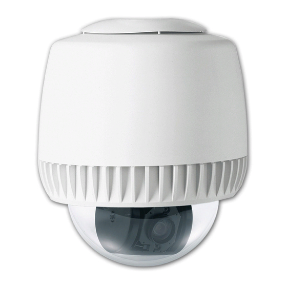
Page 7: Product Overview
Product Overview The SpeedDome LT camera dome (Figure Chapter 1-1) is part of a programmable network of camouflaged cam- eras. These devices enable security personnel, from a remote console, to track programmed targets (presets), near or far, even in low light. Small and unobtrusive, the dome can be used in facilities such as retail stores, casinos, manufacturing facilities, hotels, and hospitals, especially where appearance is important. - Page 8 Figure Chapter 1-2. Chassis components 0300-1742-00 Chassis, Indoor -01 Color NTSC camera -02 Color PAL camera -03 BW EIA camera -04 BW CCIR camera 0300-1743-01 Carriage Assy. Unicard Board (hidden) 0301-0518-03 Pan Gear 0500-3869-01 0400-0507-01 Skirt Assy., Eyeball Sector Gear 0500-3817-01 0300-1740-00 Eyeball Assy.
-
Page 9: Indoor Mounting Methods
RAS587LP-1 Monochrome CCIR (50Hz) 0100-1326-04 Chassis, Top-Level Assy. 0300-1742-04 Chassis Assy. 0300-1743-01 Carriage Assy. 0300-1740-04 Eyeball Assy. 0400-0507-01 Skirt Assy. Eyeball 0351-0558-01 Install Kit Indoor Mounting Methods The dome’s housing mounts directly to indoor hard or tile ceilings using hardware supplied with the dome or to one of several optional mounting structures. - Page 10 INTRODUCTION Figure Chapter 1-5. Indoor mounting structures (optional) RHI2X2 RHICM RHIPM RH530 SPEEDDOME LT...
-
Page 11: Features
Features Performance Features In alphabetical order: Apple Peel Default Pattern. Controller dependent, the dome automatically defaults to an “apple peel” pattern where, starting at the ceiling, the camera pans the entire viewing area three times, dropping 30° after each pan. Automatic Calibration. -
Page 12: Video System Dependent Features
Certain dome features depend on the video system the dome is used with: Sensormatic Video Manager system with RS422 Sensormatic VM8, VM16, or VM96 systems American Dynamics AD083-02A system. Following are features associated with each type of system. Video Manager System with RS422 Pan and tilt speeds of 0.5°... - Page 13 Installation & Service Features In alphabetical order: Daisy-chaining. Control cables can be daisy- chained from dome to dome (10 domes maximum for RS422), using up to 914m (3000’) of cable. (RS422 uses two, 22 AWG, individually shielded, twisted pairs; SensorNet uses one 22 AWG twisted pair without a shield.) Interchangeability.
-
Page 14: Specifications
Specifications Operational Pan/Tilt Speed... 2° to 18° per second for 12-120mm focal length 3° to 24° per second for 8-180mm focal length (based on zoom position) Pan Speed Multiplier ... 2X, 3X, 4X Pan Travel... 360° continuous Tilt Travel... >90° Zoom Optical Zoom ... - Page 15 Camera Monochrome/Color Type... Interline transfer 1/4” CCD array Scanning Area... 3.2 (H) x2.4 (V) min. Scanning System... 2:1 interlace Video Out ... 1.0Vp-p/75 ohm composite Signal-to-Noise ... 48dB (typical) Monochrome only Horizontal Resolution ... 380 lines at center Minimum Illumination ... 0.1 lux (AGC on) at f1.6 AGC...
-
Page 16: Chapter 2 Installation
“Indoor” SpeedDome LT INSTALLATION CHAPTER 2 In this chapter: Before You Begin ...2-2 Things you need to do before you install the camera dome. Installation Procedure ...2-2 Shows you how to mount the dome indoors to either a hard ceiling, tile ceiling, I-beam, pendant mount, or existing SpeedDome housing. -
Page 17: Before You Begin
Before You Begin Safety ALWAYS USE: Proper safety equipment for the location and type of installation. Proper lift equipment to reach the installation. Safety features of the lift equipment. BE SURE: Electrical power is not connected to the dome during installation. -
Page 18: Indoor Installation
Install Kit Supplied 0351-0393-01* Washer, FL, #10 x .040THK Eyebolt, 10-24 x 1-3/4”L Nut, Lock, ZN, 10-24 “S” Hook, open Chain, sash * Only parts used in this procedure are listed. Procedure Shipping box contains a template—do not throw the template out. 1. - Page 19 Procedure WARNING! Shipping box contains a template—do not throw the template out. 1. Tile ceilings only (Figure Chapter 2-2). Remove the ceiling tile(s) and inspect the ceiling frame. The frame must be capable of withstanding 9kg (20 lbs) of weight and the forces generated as the dome pans and tilts.
- Page 20 2x2 Tile Mount Installation This procedure explains how to mount the dome’s housing in ceiling tile. After completing this procedure, go to page 2-8 for chassis installation. WARNING! If ceiling frame cannot support dome, ask building maintenance to install additional ceiling supports. Install Kit Supplied 0351-0376-01* Bar, ceiling tee...
-
Page 21: Pendant Mount Installation
Extension bars (A) mount to the edge of the housing to provide proper fit. Buttjoint as many bars as required using pop rivets (B) and washers (C), four per bar, as shown below. Do not use clips. Figure Chapter 2-5. Installation using extension bars Edge of housing 5. - Page 22 2. Connect the nipple to the pipe by using the pipe tee (Figure Chapter 2-7). Thread the straight pipe (c) (not supplied) and nipple (d) into the pipe tee (e). Thread the nipple of the entire assembly into the flange. Figure Chapter 2-7.
-
Page 23: Chassis Installation
Chassis Installation This procedure explains how to mount the chassis within the dome housing. Install Kit Supplied 0351-0558-01* Connector, BNC, Plug, RG59 Connector, BNC, Jack, RG59 Cable Tie, Nylon, 4” Tubing, Heat Shrink, Black Resistor, 180-ohms, ±5%, .25W Tubing, Heat Shrink, Black * Alphabetical parts listing does not correspond to parts used in this procedure. - Page 24 WARNING! Disconnect cable from power source when performing cable conversions. Figure Chapter 2-11. Patch cable connection To Cinch-Jones To Unicard connector on composite terminal block, To Unicard BNC To video cable connector, J1 BNC connector 4. If it is necessary to replace the Cinch-Jones connector on the composite and video cables, use the male and female BNC and compression-type connectors supplied with...
-
Page 25: Bubble And Skirt Installation
Bubble and Skirt Installation This procedure explains how to mount the optional bubble assembly and skirt assembly. Procedure 1. Snap the four pins of the skirt (or bubble) assembly into the four chassis receptacles (a) (Figure Chapter 2-14). Figure Chapter 2-14. Attaching the skirt INDOOR INSTALLATION 2. -
Page 26: Chapter 3 Service
SpeedDome LT Camera Dome SERVICE CHAPTER 3 In this chapter: Before you begin ...3-2 Explains things you need to do and tools you need to have on hand before you service the camera dome. Troubleshooting...3-2 Contains procedures to help you isolate and fix a problem in the housing or the chassis and eyeball assembly. -
Page 27: Before You Begin
BEFORE YOU BEGIN This chapter contains one troubleshooting proced- ures. Before you perform this procedure, perform the following steps first: Try the troubleshooting procedure! Use this procedure to fix the problem if it is in the indoor chassis. If you cannot fix the problem, ship the indoor chassis (dome) back to the National Repair Center. - Page 28 Procedure Perform steps in sequence until the problem is corrected. 1. Check the video on the monitor. No video? Go to step 2. Is the contrast or color off? YES: Send the dome (indoor chassis) back to the National Repair Center. NO: Go to step 2.
- Page 29 6. On the Unicard board, observe the green power LED (Figure Chapter 3-3). Is the +12Vdc, green LED off or not on steady? YES: Indicates loss of power to or from power supply. Verify that the 22Vac (min.) cable is properly attached to the 7-pin connector, P3 (pins 3, 4 and 5).
-
Page 30: Dome Disassembly Techniques
Dome Functions but Does Not Pan If the dome functions but does not pan, you need to access the Unicard board (see page 3-6) and/or pan motor (see page 3-7). On the Unicard board, is the pan motor ribbon cable attached to 7-pin connector, P6 (pin 3 missing). -
Page 31: How To Remove The Unicard Board
How to Remove the Unicard Board Referring to Figure Chapter 3-4 . 1. Detach connectors. On the Unicard board, detach the two 3-pin, power supply cables from connectors P1 and P9; the 7-pin, composite cable from connectors P3 and J1; the pan motor cable from connector P6, and the 18-pin slip- ring cable from connector P8. -
Page 32: How To Remove The Pan Motor
How to Remove the Pan Motor Referring to Figure Chapter 3-5 . 1. Detach connector. On the Unicard board, detach the 7-pin cable connector from P6 (see figure for location). 2. Remove the pan motor. Remove the two M3x8, Phillips head screws securing the pan motor bracket to the carriage assembly, then remove the motor and set it aside. -
Page 33: How To Remove The Power Supply Module
How to Remove the Power Supply Module Referring to Figure Chapter 3-6 . WARNING! Unexpected pan and tilt can cause injury or damage the dome during servicing. To prevent such movement, always disconnect power/data connector P3 from the Unicard board before servicing. 1. -
Page 34: How To Remove The Clock-Spring Cable Assembly
How to Remove the Clock- Spring Cable Assembly Referring to Figure Chapter 3-7 . 1. Remove the lens and camera shrouds. When removing the four screws from each shroud, you may want to use a screwdriver with a magnetic tip. 2. -
Page 35: How To Remove The Camera Assembly
How to Remove the Camera Assembly Referring to Figure Chapter 3-8 . WARNING! Unexpected pan and tilt can cause injury or damage the dome during servicing. To prevent such movement, always disconnect power/data connector P3 from the Unicard board before servicing. 1. -
Page 36: How To Remove The Camera/Lens Board
How to Remove the Camera/Lens Board Referring to Figure Chapter 3-9 . WARNING! Unexpected pan and tilt can cause injury or damage the dome during servicing. To prevent such movement, always disconnect power/data connector P3 from the Unicard board before servicing. 1. -
Page 37: How To Remove The Tilt Motor
How to Remove the Tilt Motor Referring to Figure 3-10. 1. Detach connector. On the camera/lens board, detach the 7-pin cable connector from P2. 2. Remove the screws that secure the tilt motor to the eyeball casting. Remove the two M3x10, Phillips head screws securing the tilt motor bracket to the eyeball casting, then remove the motor and set it aside. -
Page 38: How To Remove The Slip-Ring Assembly
How to Remove the Slip-Ring Assembly Referring to Figure Chapter 3-11 . WARNING! Unexpected pan and tilt can cause injury or damage the dome during servicing. To prevent such movement, always disconnect power/data connector P3 from the Unicard board before servicing. 1. -
Page 39: How To Remove The Eyeball Assembly
How to Remove the Eyeball Assembly Referring to Figure Chapter 3-12 . WARNING! Unexpected pan and tilt can cause injury or damage the dome during servicing. To prevent such movement, always disconnect power/data connector P3 from the Unicard board before servicing. 1. -
Page 40: Dome Maintenance
Dome Maintenance Setting Communications Jumpers To set the communications jumpers on the Unicard: 1. Set the jumpers to RS422 or SensorNet (Figure Chapter 3-13). Using Figure Chapter 3-13, set jumpers E2 and E3 according to your network requirements. Communications Jumpers Cable Type RS422 2 - 3... - Page 41 AMERICAN DYNAMICS Sensormatic CCTV Systems Division One Blue Hill Plaza Pearl River, NY 10965 Technical Support Center 1-800-442-2225 Business (914) 624-7600 SENSORMATIC ELECTRONICS 951 Yamato Road Boca Raton, FL 33431-4425 Technical Support Center 1-800-543-9740 Business (561) 989-7000...
Need help?
Do you have a question about the SpeedDome Optima LT and is the answer not in the manual?
Questions and answers