Table of Contents
Advertisement
Quick Links
Advertisement
Table of Contents

Subscribe to Our Youtube Channel
Summary of Contents for Phoenix Contact SCX 4POE 2LX
- Page 1 Smart Camera Box User manual UM EN SCX xPOE...
- Page 2 This user manual is valid for: Designation Software Release Order No. SCX 4POE 2LX 1102626 SCX 2POE 2LX 1108543 SCX 4POE 2T 1108542 SCX 2POE 2T 1108544 PHOENIX CONTACT GmbH & Co. KG • Flachsmarktstraße 8 • 32825 Blomberg • Germany phoenixcontact.com...
-
Page 3: Table Of Contents
Device replacement, device defects, and repairs ..............63 Device replacement..................... 63 Device defects and repairs .................. 65 Maintenance and disposal .......................66 Maintenance......................66 Disposal ......................67 Technical data .........................69 Ordering data ...................... 69 Technical data ..................... 70 3 / 108 109008_en_01 PHOENIX CONTACT... - Page 4 RSTP – Rapid Spanning Tree Protocol..............77 SNMP – Simple Network Management Protocol ..........87 LLDP – Link Layer Discovery Protocol..............90 Appendixes..........................93 List of figures ....................... 93 List of tables ......................95 Index........................103 4 / 108 PHOENIX CONTACT 109008_en_01...
-
Page 5: For Your Safety
If in doubt, consult an Ethernet network specialist to assess the use of the devices and the set configuration. 5 / 108 109008_en_01 PHOENIX CONTACT... -
Page 6: Safety Notes
Incorrect operation or modifications can endanger your safety or damage the Smart Camera Box. You may not repair the Smart Camera Box or its components yourself. • If the Smart Camera Box is defective, please contact Phoenix Contact. Safety notes •... -
Page 7: Electrical Connection
Make sure that the power cannot be switched back on Verify safe isolation from the supply Ground and short circuit Cover or safeguard adjacent live parts Once the work is complete, perform the above steps again in reverse order. 7 / 108 109008_en_01 PHOENIX CONTACT... - Page 8 c) A multiple-pole circuit breaker used as an overcurrent protective device or devices shall be so constructed as to interrupt all of the neutral (grounded) and ungrounded conductors of the MAINS supply simultaneously. 8 / 108 PHOENIX CONTACT 109008_en_01...
- Page 9 75 °C, AWG 24 ... 10 Use copper conductors only. Minimum temperature rating of the cable to be connected to the field wiring terminals (Digital output) 75 °C, AWG 24 ... 16 Use copper conductors only. 9 / 108 109008_en_01 PHOENIX CONTACT...
-
Page 10: Security In The Network
Phoenix Contact GmbH & Co. KG, Flachsmarktstraße 8, 32825 Blomberg, Germany in accordance with §§ 15 ff AktG (German Stock Corporation Act), hereinafter collectively referred to as “Phoenix Contact”, from all third-party claims made due to improper use. • For the protection of networks for remote maintenance via VPN, Phoenix Contact offers the mGuard product range of security appliances, a description of which you will find in the latest Phoenix Contact catalog (phoenixcontact.net/products). - Page 11 For your safety 11 / 108 109008_en_01 PHOENIX CONTACT...
-
Page 12: Transport, Storage, And Unpacking
– – Protected from unauthorized access – Protected from harmful environmental influences such as UV light • For storage, observe the humidity and air pressure specifications, and the temperature range. “Ambient conditions” on page 10 / 108 PHOENIX CONTACT 109008_en_01... -
Page 13: Unpacking
Immediately upon delivery, refer to the delivery note to ensure that the delivery is com- plete. • Submit claims for any transport damage immediately, and inform Phoenix Contact or your supplier as well as the shipping company without delay. •... - Page 14 SCX xPOE... 12 / 108 PHOENIX CONTACT 109008_en_01...
-
Page 15: Product Description
Table 3-1 Overview of product versions Designation Number of PoE Uplink ports ports SCX 4POE 2LX 2 SFP slots SCX 2POE 2LX For SFP modules available as accessories, “Accessories” SCX 4POE 2T 2 RJ45 jacks SCX 2POE 2T Licensing information on open source software You will find the licensing information in the web-based management of the device. -
Page 16: Design
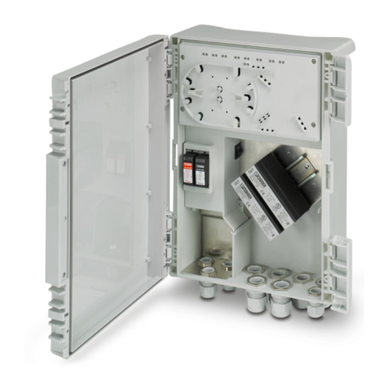
M25 cable gland (data, low voltage zone, <50 V AC/<120 V DC) POE3/4 Power over Ethernet ports 3 and 4 M20 cable gland (supply, mains voltage zone) (SCX 4POE 2LX only) POE1/2 Power over Ethernet ports 1 and 2 Grounding screw CONF Local configuration port Push-in connection, supply voltage, 100 ... - Page 17 , PoE voltage is present at the port Flashing Error, e.g., negotiated performance exceeded, PD not supplied All LEDs Green Boot process In force mode, the LEDs do not indicate whether or not power is supplied to a PD. 15 / 108 109008_en_01 PHOENIX CONTACT...
- Page 18 UP1/2 Ethernet uplink ports Push-in connection, supply voltage, 100 ... 240 V AC +/- AUX 24 V DC, switching output, configura- Surge protection, pluggable tion via web-based management Switch, device ON/OFF Surge protection, pluggable 16 / 108 PHOENIX CONTACT 109008_en_01...
- Page 19 , PoE voltage is present at the port Flashing Error, e.g., negotiated performance exceeded, PD not supplied All LEDs Green Boot process In force mode, the LEDs do not indicate whether or not power is supplied to a PD. 17 / 108 109008_en_01 PHOENIX CONTACT...
- Page 20 Openings with breathable membranes to prevent build up of condensation Removal opening, side Removal opening, lower 3.2.4 Zones in the Smart Camera Box Figure 3-4 Zones in the Smart Camera Box Mains voltage zone Low voltage zone (<50 V AC/<120 V DC) 18 / 108 PHOENIX CONTACT 109008_en_01...
- Page 21 Only open the housing when the device is de-energized. • Open the housing using a screwdriver. • The door is hinged either on the left or right (1 + 2 or 3 + 4) Figure 3-5 Opening the housing 19 / 108 109008_en_01 PHOENIX CONTACT...
- Page 22 SCX xPOE... 20 / 108 PHOENIX CONTACT 109008_en_01...
-
Page 23: Installation
– When working on the Smart Camera Box, make sure that there is sufficient room to move. Also ensure that there is sufficient space available for mounting, operation, and maintenance. 21 / 108 109008_en_01 PHOENIX CONTACT... - Page 24 In this case, tighten the mast clamps with the recommended torque after alignment. Ø50 ... 90mm Ø90 ... 250mm Figure 4-1 Mounting adapter, mast mounting Figure 4-2 Mast mounting example, Ø 50 ... 90 mm 22 / 108 PHOENIX CONTACT 109008_en_01...
- Page 25 M6 screws. • Push the Smart Camera Box onto the mounting adapter from above until it securely engages. • Make sure that it is firmly attached. Figure 4-3 Mounting adapter, wall mounting 23 / 108 109008_en_01 PHOENIX CONTACT...
- Page 26 Pull the Smart Camera Box up. Figure 4-4 Removal Removing SFP modules • SCX 4POE 2LX and SCX 2POE 2LX only: Turn the release latch to the side and pull off the SFP module (see Figure 4-10). 24 / 108...
-
Page 27: Electrical Connection
Once the work is complete, perform the above steps again in reverse order. NOTE: Electrostatic discharge Electrostatic discharge can damage or destroy components. – Observe the necessary safety precautions against electrostatic discharge (ESD) in accordance with EN 61340-5-1 and IEC 61340-5-1. 25 / 108 109008_en_01 PHOENIX CONTACT... - Page 28 Figure 4-5 Cable glands Pos. Connection Conductor Stripping Cable diameter cross section length Supply 1 ... 6 mm² 10 mm 6 ... 12 mm 6 ... 10 mm Data 6 ... 12 mm 26 / 108 PHOENIX CONTACT 109008_en_01...
- Page 29 Tighten the cable glands with 2 Nm (M20) or 3.5 Nm (M25). • Ensure that the seal insert tightly encloses the cable. Figure 4-6 Assembling the M20 cable gland Figure 4-7 Assembling the M25 cable gland 27 / 108 109008_en_01 PHOENIX CONTACT...
- Page 30 Do not feed the supply voltage into the low voltage zone inside the Smart Camera Box. L(b) N(b) PE(b) L(a) N(a) PE(a) Figure 4-8 Connecting the supply voltage Figure 4-9 1 = mains voltage zone / 2 = low voltage zone 28 / 108 PHOENIX CONTACT 109008_en_01...
- Page 31 Insert the SFP modules into the SFP slots in the Smart Camera Box. • As you do so, make sure the SFP modules are correctly mechanically aligned. • Insert the splice tray. Figure 4-10 SFP module 29 / 108 109008_en_01 PHOENIX CONTACT...
- Page 32 Strip the sheath around the fiber bundles. • Fix the fiber bundles in place using the cable ties supplied. Ø6...12 Figure 4-11 Stripping an FO cable, M20 cable gland Figure 4-12 Inserting the FO cables 30 / 108 PHOENIX CONTACT 109008_en_01...
- Page 33 Fix the wires to the respective plastic stays using the cable ties supplied. • Route the fibers approximately 3 times through the splice cartridge up to the center of the splice tray. • Trim the fibers accordingly. 31 / 108 109008_en_01 PHOENIX CONTACT...
- Page 34 Use the specified conductor cross sections and stripping lengths for the 24 V output (see “Switching output”). – Installing additional devices may have an effect on the CE conformity of the Smart Camera Box. You may need to reassess the CE conformity. 32 / 108 PHOENIX CONTACT 109008_en_01...
-
Page 35: Commissioning
Before applying the supply voltage, check all conductive connections. • If the Smart Camera Box has been connected correctly, switch on the backup fuse. Configuring the Smart Camera Box is described in Section 5, “Configuration”. 33 / 108 109008_en_01 PHOENIX CONTACT... - Page 36 1184401). The padlock is not included in the scope of supply. You will need a pad- lock with a shackle diameter of up to 12 mm. Figure 4-15 SCX-DOOR-LOCK: Attaching the locking tab Figure 4-16 SCX-DOOR-LOCK: Mounting the door lock 34 / 108 PHOENIX CONTACT 109008_en_01...
-
Page 37: Configuration
Enter the IP address in the address field of your browser. • You need the user name and password to log in. – User name: admin (default) – Password: private (default) NOTE: Network security Change the password during initial configuration (see “Basic setup”). 35 / 108 109008_en_01 PHOENIX CONTACT... - Page 38 The changed parameters will be transmitted to the device. NOTE: The changes are not yet permanently saved. They will be lost in the event of a device restart. The changes are saved permanently. 36 / 108 PHOENIX CONTACT 109008_en_01...
- Page 39 Time information, e.g., in the event table, is specified in Greenwich Mean Time (GMT, standard time). The local time is calculated from the system time and the UTC offset. – Select your time zone. Where necessary, note the changeover between daylight sav- ing and standard time. 37 / 108 109008_en_01 PHOENIX CONTACT...
- Page 40 User management Administration, User Management User Name admin; cannot be changed NOTE: For security reasons, change the password during initial configuration. Administrator Password, Retype Password 8 ... 64 characters, allowed characters: A...Z, a...z, 0...9 38 / 108 PHOENIX CONTACT 109008_en_01...
- Page 41 Primary Server Description Description of the primary or secondary SNTP server Secondary Server Descrip- tion Synchronization Status Synchronization status Last SNTP Synchronization Device Name Enter information about the device. Device Description Physical Location Device Contact 39 / 108 109008_en_01 PHOENIX CONTACT...
- Page 42 The current security context (HTTPS and SSH certificates) will be written to a file. You can File upload this file to a different Smart Camera Box later. Root CA Clicking on “cacert.cer” loads the Root CA certificate for the installation in the browser. 40 / 108 PHOENIX CONTACT 109008_en_01...
- Page 43 UDP port of the RADIUS server Radius Shared Secret Enter the shared secret for encrypted communication with the RADIUS server. – Maximum 128 characters – Letters, numbers, and the following special characters can be used: $%@&/\()?=[]{}*-_<>#^.,:~| 41 / 108 109008_en_01 PHOENIX CONTACT...
- Page 44 Force Unauthenticate: none of the devices connected to the port are authenticated. Re-Authentication Disabled: no re-authentication Mode Enabled: regular re-authentication Re-Authentication Regular re-authentication of the participant at the specified Period (secs) interval; 1 ... 65535 seconds 42 / 108 PHOENIX CONTACT 109008_en_01...
- Page 45 The file name must not include any of the following characters: /\<>:|?*space Update Status Status of the firmware update NOTE: The Smart Camera Box must remain connected to the supply voltage during the update. 43 / 108 109008_en_01 PHOENIX CONTACT...
- Page 46 Reboot Device & Factory Defaults Administration, Reboot Device & Factory Defaults NOTE: Restart, all unsaved changes will be lost! Reboot Device NOTE: Reset to factory defaults, all changes will be lost! Factory Default 44 / 108 PHOENIX CONTACT 109008_en_01...
- Page 47 (Address Conflict Detection) mode, this will be detected. The participants are displayed via the MAC address. The changes will only be applied after a restart. None Address conflict detection disabled Address conflict detection enabled 45 / 108 109008_en_01 PHOENIX CONTACT...
- Page 48 Priority for data packets arriving at this port, if they do not already include a priority in the form of a tag Flow Control Disabled: data flow control disabled Enabled: data flow control for the greatest possible data transmission continuity without losses 46 / 108 PHOENIX CONTACT 109008_en_01...
- Page 49 Select the target port at which the data is to be issued. Mirrored Ports (Ingress) Incoming data traffic at the selected port will be mirrored. Mirrored Ports (Egress) Outgoing data traffic at the selected port will be mirrored. 47 / 108 109008_en_01 PHOENIX CONTACT...
- Page 50 The web-based management or network therefore cannot be accessed via a MAC address that is permitted at another port. Add new entry Enter a new permitted MAC address for the port. 48 / 108 PHOENIX CONTACT 109008_en_01...
- Page 51 Configuration, Power Over Ethernet PoE Power Threshold Percentage of the power budget If a value above or below this switching threshold is reached, an SNMP trap is sent. To configure the SNMP traps, see “SNMP”. 49 / 108 109008_en_01 PHOENIX CONTACT...
- Page 52 The PoE class determines the maximum power available at the port – In Auto mode: maximum class that can be assigned – In Force mode: maximum possible power output. If the value is exceeded, the port is disabled. 50 / 108 PHOENIX CONTACT 109008_en_01...
- Page 53 Limit Value [%] Disabled No bandwidth monitoring Enabled If the value falls below the lower switching threshold or exceeds the upper switching threshold, the watchdog is trig- gered. Select a value between 0.01 ... 100%. 51 / 108 109008_en_01 PHOENIX CONTACT...
- Page 54 Each ring is assigned an ID. This ID is communicated to every switch in the respective ring. One switch can belong to several different rings at the same time. Switch-over time: 500 ms Disabled Fast Ring Detection disabled Enabled Fast Ring Detection enabled 52 / 108 PHOENIX CONTACT 109008_en_01...
- Page 55 Non-Edge: the port is not an edge port. Edge: the port is an edge port. Priority Port priority The port with the higher value has a lower priority. Value: 0 ... 240 in increments of 16 53 / 108 109008_en_01 PHOENIX CONTACT...
- Page 56 Add New Trap Receiver Add a trap server that is to receive SNMP traps. Trap List All SNMP traps that the device can send Select the actions for which SNMP traps are to be sent. 54 / 108 PHOENIX CONTACT 109008_en_01...
- Page 57 VLAN. – If the port receives frames, it can only forward these in a VLAN with the same VLAN ID that also sends frames to this port. 55 / 108 109008_en_01 PHOENIX CONTACT...
- Page 58 Port not selected: the port ignores LLDP telegrams. : The port evaluates received LLDP telegrams. LLDP Transmission Port not selected: the port does not send LLDP telegrams. : The port sends LLDP telegrams at the configured interval. 56 / 108 PHOENIX CONTACT 109008_en_01...
- Page 59 NOTE: The events will be deleted in the event of a restart. Persistent Event Logging Disabled Enabled Events will be saved permanently Frequent permanent saving can reduce the lifespan of the internal memory. 57 / 108 109008_en_01 PHOENIX CONTACT...
- Page 60 You can reset all statistics to “0” using “Clear”. 5.1.5.6 Port utilization Here, you can view the utilization of the ports in the form of diagrams. 58 / 108 PHOENIX CONTACT 109008_en_01...
- Page 61 Power output, total 5.1.5.9 Network redundancy You will find all information on the RSTP status and the virtual ports here. 5.1.5.10 LLDP topology You will find information on the neighboring ports and connected devices here. 59 / 108 109008_en_01 PHOENIX CONTACT...
-
Page 62: Mode Button
Press and hold the button down for at least five seconds. Once all LEDs light up solid, release the button. ⇒ The last selected function has now been saved and enabled. If you have selected “Reset to factory defaults” or “DHCP”, the switch will be restarted. 60 / 108 PHOENIX CONTACT 109008_en_01... - Page 63 You must configure these redundancy mechanisms in Managed mode. They will remain active when switching to Unmanaged mode. Exiting Unmanaged mode • Select another function in Smart mode. • Reset the device to the default settings. 61 / 108 109008_en_01 PHOENIX CONTACT...
-
Page 64: Behavior During Restart And In The Event Of An Error
Uplink ports: data connection – Switching output (+/- AUX): supply voltage All ports are disabled during the restart. The ports are enabled or disabled following the restart, depending on the saved configura- tion. Disabled ports remain disabled. 62 / 108 PHOENIX CONTACT 109008_en_01... -
Page 65: Device Replacement, Device Defects, And Repairs
You can replace the Smart Camera Box if necessary. • Remove the Smart Camera Box as described in “Removal” on page • Replace the Smart Camera Box with an identical Smart Camera Box (same Order No.). 63 / 108 109008_en_01 PHOENIX CONTACT... - Page 66 Replace the module with a module of the same type (see Table 6-1). • Observe the instructions in the packing slip for the module. defekt VALVETRAB VALVETRAB VAL-MS VAL-MS Figure 6-2 Surge protection modules 64 / 108 PHOENIX CONTACT 109008_en_01...
-
Page 67: Device Defects And Repairs
Repairs may only be carried out by the manufacturer. The manufacturer is not liable for damage resulting from non-compliance. • Send defective devices back to Phoenix Contact for repair or to receive a replacement device. • We strongly recommend using the original packaging to return the product. -
Page 68: Maintenance And Disposal
Check all seals for deformation, cracks, and soiling. All seals must be maintained at regular intervals to ensure that the housing offers the appropriate degree of protection. • Condition all seals with suitable care products. 66 / 108 PHOENIX CONTACT 109008_en_01... -
Page 69: Disposal
Dispose of the device separately from other waste, i.e., via an appropriate collection site. • Dispose of packaging materials that are no longer needed (cardboard packaging, paper, bubble wrap sheets, etc.) with household waste in accordance with the currently applicable national regulations. 67 / 108 109008_en_01 PHOENIX CONTACT... - Page 70 SCX xPOE... 68 / 108 PHOENIX CONTACT 109008_en_01...
-
Page 71: Technical Data
Smart Camera Box for connecting PoE end devices, Managed Switch, integrated surge protection, supply voltage 100 ... 240 V AC, wall or mast mounting 4 PoE ports, 2 uplink ports (SFP slots) SCX 4POE 2LX 1102626 2 PoE ports, 2 uplink ports (SFP slots) SCX 2POE 2LX... - Page 72 2702889 firmware update software, for easy commissioning of BASIC Managed Switches SFP modules for SCX 4POE 2LX and SCX 2POE 2LX Gigabit SFP WDM module for transmission up to 10 km FL SFP WDM10-B 2702441 via one fiber on a wavelength of 1550/1310 nm...
- Page 73 Transmission medium Depending on the SFP module used Copper Transmission speed 100/1000 Mbps (depending on the SFP 10/100/1000 Mbps module used) Transmission length <80 km (depending on the SFP module 100 m (per segment) used) 71 / 108 109008_en_01 PHOENIX CONTACT...
- Page 74 0.25 mm² ... 1.5 mm² (stripping length 8 mm) flexible, with ferrule, with plastic sleeve 0.25 mm² ... 0.75 mm² (stripping length 8 mm) If you use the switching output, the available PoE power will be reduced by 10 W. 72 / 108 PHOENIX CONTACT 109008_en_01...
- Page 75 15g, 11 ms Enclosure (UL50/50E): UL (NEMA) Enclosure Type Rating: 4X, watertight and corrosion resistant, suitable for indoor or outdoor use MTTF (Mean Time To Failure), SCX 4POE 2LX SCX 2POE 2LX SCX 4POE 2T SCX 2POE 2T SN 29500 standard Temperature 25°C, operating cycle...
- Page 76 Derating per port Conformity/approvals CE-compliant UL, USA / Canada Listed UL 61010-1, 3rd Edition UL 61010-2-201, 2nd Edition CAN/CSA C22.2 No. 61010-1-12 CSA C22.2 No. 61010-2-201:18 Corrosive gas test ISA-S71.04-1985 G3 Harsh Group A 74 / 108 PHOENIX CONTACT 109008_en_01...
- Page 77 Conducted noise emission EN 61000-6-3 Class B, domain of use: residential and small commercial Criterion A Normal operating behavior within the specified limits Criterion B Temporary impairment of operating behavior that is corrected by the device itself 75 / 108 109008_en_01 PHOENIX CONTACT...
- Page 78 SCX xPOE... Dimensions Figure 8-3 Dimensions 76 / 108 PHOENIX CONTACT 109008_en_01...
- Page 79 Surge Protection Logic Surge Protection DIN rail (23) (24) Grounding screw VAL-MS 230 ST VAL-MS 350 VF ST (23) (24) VAL-MS 320 HD ST F-MS 12 HD ST Figure 8-5 Basic circuit diagram SCX...2T 77 / 108 109008_en_01 PHOENIX CONTACT...
- Page 80 SCX xPOE... 78 / 108 PHOENIX CONTACT 109008_en_01...
-
Page 81: A Technical Appendix
In the event of a link down, all the entries of the respective port will be deleted. – You will find a list of detected MAC addresses in the MAC address table. – You can set the aging time via the “dot1dTpAgingTime” MIB object (OID 1.3.6.1.2.1.17.4.2). 75 / 108 109008_en_01 PHOENIX CONTACT... - Page 82 Quality of Service affects the forwarding and handling of data streams and results in individ- ual data streams being treated differently (usually preferential). With QoS, for example, you can guarantee a transmission bandwidth for individual data streams. The switch uses QoS in connection with prioritization. 76 / 108 PHOENIX CONTACT 109008_en_01...
-
Page 83: A 2 Rstp - Rapid Spanning Tree Protocol
The path costs are used to decide which ports are to be blocked and which are to be pre- ferred. The path costs are determined automatically based on the bandwidth. However, you can also specify a value manually. 77 / 108 109008_en_01 PHOENIX CONTACT... - Page 84 Furthermore, a data path can consist of the connection of a Spanning Tree switch to the fol- lowing: – An end device – A network segment consisting of several infrastructure components not supported by Spanning Tree. In this network segment, no loops are permitted. 78 / 108 PHOENIX CONTACT 109008_en_01...
- Page 85 These timers are set using the default values recommended by the IEEE standard such that a topology with a maximum of 10 active Spanning Tree com- ponents always results in a stable network. 79 / 108 109008_en_01 PHOENIX CONTACT...
- Page 86 100 to 500 ms with Fast Ring Detection. It is only possible to access the maximum number of 57 switches when “Large Tree Sup- port” is enabled at the same time. 80 / 108 PHOENIX CONTACT 109008_en_01...
- Page 87 1 2 3 4 5 6 7 8 9 10 1112 DI2 UI MODE RESET GNDI GNDI DI1 DI2 V.24 FAIL LNK/ACT SWITCH 2000 10 11 12 13 14 15 16 Figure 8-5 Redundant coupling of network segments 81 / 108 109008_en_01 PHOENIX CONTACT...
- Page 88 Root path (bridge identification)? Highest priority for Same priority for individual ports? port Root path Lowest port number Root path Path to root switch is determined Figure 8-6 Flow chart for determining the root path 82 / 108 PHOENIX CONTACT 109008_en_01...
- Page 89 Initially therefore, it is sufficient to change the values in the root switch. If the root switch fails, the timer values of another active RSTP switch (the new root switch) will be valid for the en- tire network segment. Ensure this behavior when configuring your components. 83 / 108 109008_en_01 PHOENIX CONTACT...
- Page 90 Ord. No. 29 89 200 Address FAIL 1 2 3 4 5 6 7 8 9 10 1112 DI2 UI MODE RESET GNDI GNDI DI1 DI2 V.24 Figure 8-7 Example 1 for the “relevant path” 84 / 108 PHOENIX CONTACT 109008_en_01...
- Page 91 1 2 3 4 5 6 7 8 9 10 1112 DI2 UI MODE RESET Relevant path GNDI GNDI DI1 DI2 V.24 for the setting of the timer values Figure 8-8 Example 2 for the “relevant path” 85 / 108 109008_en_01 PHOENIX CONTACT...
- Page 92 FAIL LNK/ACT SWITCH 2000 10 11 12 13 14 15 16 MODE FAIL FAIL LNK/ACT SWITCH 2000 10 11 12 13 14 15 16 MODE FAIL Figure 8-9 Topology example for Large Tree Support 86 / 108 PHOENIX CONTACT 109008_en_01...
-
Page 93: A 3 Snmp - Simple Network Management Protocol
The descriptions of the individual SNMP objects can be found in the respective MIBs. You can download these at phoenixcontact.net/products. You will find the MIB in the respective software packet (zip file) of a firmware package. 87 / 108 109008_en_01 PHOENIX CONTACT... - Page 94 It cannot be reused, for example with other parameters, under any circumstances. Phoenix Contact provides notification of the ASN1 SNMP objects by publishing their de- scriptions on the Internet pages. Reading SNMP objects is not password-protected. You have to enter a password for read access in SNMP, but this is set to “public”.
- Page 95 DES as the algorithm for privacy – Username: admin – Password: current device password The password must have a minimum length of eight characters. If the default password is “private”, you have to use “private_” for access. 89 / 108 109008_en_01 PHOENIX CONTACT...
-
Page 96: A 4 Lldp - Link Layer Discovery Protocol
If several neighbors are displayed on one switch port, then at least one other switch that does not support LLDP or in which LLDP is not enabled is installed between this switch and the neighbor displayed. 90 / 108 PHOENIX CONTACT 109008_en_01... - Page 97 BPDUs to all ports Aging (Time To Live) Delete neighborhood infor- mation Receipt of a BPDU from a Extend list of neighbors, Include sender in the list of new neighbor respond with port-specific neighbors BPDU 91 / 108 109008_en_01 PHOENIX CONTACT...
- Page 98 SCX xPOE... 92 / 108 PHOENIX CONTACT 109008_en_01...
-
Page 99: Appendixes
Firmware update ................. 43 Figure 5-7: Config up/Download ................44 Figure 5-8: Reboot Device & Factory Defaults ............44 Figure 5-9: Network ....................45 Figure 5-10: Port configuration ................46 Figure 5-11: Port mirroring ..................47 93 / 108 109008_en_01 PHOENIX CONTACT... - Page 100 Flow chart for determining the root path ..........82 Figure 8-7: Example 1 for the “relevant path” ............84 Figure 8-8: Example 2 for the “relevant path” ............85 Figure 8-9: Topology example for Large Tree Support ......... 86 94 / 108 PHOENIX CONTACT 109008_en_01...
-
Page 101: List Of Tables
SCX xPOE 2LX LEDs ................15 Table 3-3: SCX xPOE 2T LEDs ................17 Table 5-1: Revert, Apply, Save ................36 Table 5-2: LEDs in smart mode ................60 Table A-1: Event table for LLDP................91 95 / 108 109008_en_01 PHOENIX CONTACT... - Page 102 SCX xPOE... 96 / 108 PHOENIX CONTACT 109008_en_01...
-
Page 103: Index
Conversions ..............6 Installation..............21 Installing additional devices ........32 Insulation testing ............67 Intended use ..............6 Data security ..............8 Interlocking ..............34 Daylight saving time ............ 37 IP Address Assignment..........37 103 / 108 109008_en_01 PHOENIX CONTACT... - Page 104 Splice cartridge ............29 SSH ................40 Password ..............35 SSH certificate ............40 Ping................51 Standard time ............. 37 PoE watchdog............. 51 Static IP address ............37 Port Configuration ............46 Storage ............... 10 104 / 108 PHOENIX CONTACT 109008_en_01...
- Page 105 User management............38 User name ..............35 UTC Offset ..............37 VAL-MS..............64 VLAN ................55 Wall mounting ............. 23 Watchdog..............51 Web browser............... 35 Web-based management..........35 Starting..............35 Winter time..............37 105 / 108 109008_en_01 PHOENIX CONTACT...
- Page 106 SCX xPOE... 106 / 108 PHOENIX CONTACT 109008_en_01...
- Page 107 The receipt of technical documentation (in particular user documentation) does not constitute any further duty on the part of Phoenix Contact to furnish information on modifications to products and/or technical documentation. You are responsible to verify the suitability and intended use of the products in your specific application, in particular with regard to observing the applicable standards and regulations.
- Page 108 Should you have any suggestions or recommendations for improvement of the contents and layout of our manuals, please send your comments to: tecdoc@phoenixcontact.com PHOENIX CONTACT GmbH & Co. KG • Flachsmarktstraße 8 • 32825 Blomberg • Germany 108 / 108 phoenixcontact.com...
Need help?
Do you have a question about the SCX 4POE 2LX and is the answer not in the manual?
Questions and answers