Advertisement
Quick Links
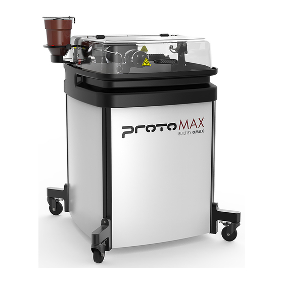
ProtoMAX®
Operation Guide
Lockout/Tagout
Implement standard practices and procedures to shut down equipment, isolate it
from its energy source(s), and prevent the release of potentially hazardous energy
while maintenance and servicing activities are being performed.
Equipment Grounding Requirements
Advertisement

Related Manuals for Omax ProtoMAX


Summary of Contents for Omax ProtoMAX
- Page 1 ProtoMAX® Operation Guide Lockout/Tagout Implement standard practices and procedures to shut down equipment, isolate it from its energy source(s), and prevent the release of potentially hazardous energy while maintenance and servicing activities are being performed. Equipment Grounding Requirements...
- Page 2 Do not use extension cords with the equipment. • If the cord is damaged or worn, immediately replace it. Contact OMAX for • replacement parts and instructions for replacement. The insulation of the EGC is covered with a green or green with yellow-striped surface. If replacement of the electric cord or plug is necessary, do not connect the equipment-grounding conductor to a live terminal.
- Page 3 • No adapter is available, or should be used with this equipment. • For countries other than United States, Canada and Mexico; OMAX does not • supply a suitably rated industrial grade plug. Contact a qualified electrician or service personnel for installation of a suitably •...
- Page 4 You must plug the cord into a matching outlet that is properly installed and • grounded in accordance with all local codes and ordinances. Figure 208 Explosive Atmosphere Precautions Machining certain types of material such as titanium with a waterjet may produce sparks.
- Page 5 Allen wrench 4 mm Open-end wrench 19 mm Crowfoot wrench 19 mm OMAX Provided Tools The following table contains a list of tools provided by OMAX that are needed to operate the ProtoMAX. Tools listed with part numbers are included with...
- Page 6 CAD drawing files. Components The ProtoMAX takes up little shop floor space. The cutting stage has a 12 in. (30 cm) (X-axis) by 12 in. (30 cm) (Y-axis) cutting area with an easy material alignment system for cutting parts. The precision drive components are protected inside sealed bellows from water and garnet abrasive.
- Page 7 Figure 209 1] Table assembly [2] High-pressure pump Table Assembly The ProtoMAX table assembly is comprised of the cutting stage, garnet abrasive delivery system, catcher tank, electrical control enclosure, water filter, and operator controls. Figure 210...
- Page 8 NOTICE Do not remove the side panels under normal conditions. Damage may occur when operating the ProtoMAX with the side panels removed. Only remove them when required by maintenance or troubleshooting procedures. The cutting stage lid provides safe access to view the cutting process. The lid has a built in safety interlock switch that halts all cutting operations (pauses MAKE, stops stage motion, and turns off the pump) when the lid is opened.
- Page 9 MAX software. When looking down on the table, the X-axis runs left to right and the Y-axis runs front to back. The Z-axis allows vertical movement of the cutting head. When the ProtoMAX is homed, the nozzle is moved to the position X=0 and Y=0 coordinate at the lower left corner of the cutting envelope.
- Page 10 The catcher tank stores the water from the cutting nozzle and provides a settling tank for the spent garnet abrasive and cut away material. The catcher tank bottom is shielded to prevent cutting through when operating the machine. NOTICE Do not add chemicals to the catcher tank water. Damage to the catcher tank and other components may occur.
- Page 11 [3] Holding post [3] Holding arm, long Power Switch AC power is controlled by a power switch located on the electrical control enclosure. All ProtoMAX system power is removed when OFF. Figure 217 [3] Power OFF [1] Power ON position...
- Page 12 Tube routing is for illustration purposes only. NOTE: Always use garnet abrasive purchased from OMAX. This high-quality abrasive is more consistent in particle size and contains less dust. Inconsistency in particle size makes it difficult to maintain quality when cutting and increases the likelihood of the mixing tube becoming clogged.
- Page 13 High-pressure Pump The high-pressure pump provides approximately 30,000 pounds per square inch (psi) of cutting pressure for the ProtoMAX. Output high-pressure from the pump is automatically controlled by a variable frequency drive (VFD). The software helps prevent damage to the pump by halting operation when there is inadequate...
- Page 14 NOTICE Do not operate the ProtoMAX without the incoming water supply filter. Operating the ProtoMAX without the water supply filter will introduce debris into the system and may damage the pump and high-pressure system. Figure 221 [1] Water manifold...
- Page 15 [8] Water connec [3] Water pressure gauge [6] Water filter assembly Laptop The ProtoMAX laptop is pre-installed with Intelli-MAX software and is connected to the ProtoMAX by a USB cable. Figure 222 Intelli-MAX® Proto Software Intelli-MAX software by OMAX is easy-to-use and maximizes the functionality of the ProtoMAX Abrasive Waterjet.
- Page 16 drawing files (.dxf) for machining. Drawing files may also be imported from other CAD programs. 2. Assign machining qualities (edge finish). The next step is to assign machining qualities (edge finish) to the drawing entities (lines, arcs, etc.) that tell the nozzle how fast or slow to move to obtain the desired edge finish.
- Page 17 Operate the ProtoMAX See the Intelli-MAX® Help system for additional information on using LAYOUT and MAKE software. Startup Checklist Startup Overview The following checklist is a quick reference to ensure equipment startup tasks are completed in the required sequence. Detailed instructions are located in Start ProtoMAX.
- Page 18 Startup Overview 1. Turn ON the laptop power. NOTE: Do not open MAKE. The ProtoMAX USB cable must be plugged in and recognized by the laptop before opening the MAKE program. 2. Connect the ProtoMAX USB cable [1] to the laptop.
- Page 19 6. Open the MAKE software. 7. Click the Machine needs to be homed banner to home the machine. NOTE: Home is required after every power cycle. For example, when the main power switch is turned OFF and then turned back ON, during power outages, or the main power cord is disconnected.
- Page 20 Figure 227 b. Remove the abrasive feed tube from the nozzle and place it over the top of the Y-axis [1]. Figure 228 c. Verify the mixing tube is properly seated and secured in the nozzle body. Figure 229 d. Place the nozzle splash guard [1] on the mixing tube [2] with the cup folded Figure 230...
- Page 21 e. Position the nozzle in the center of the tank, between two slats using the X, Y Jog buttons or keyboard arrow keys. Figure 231 f. Lower the nozzle to within 1 in. of the surface of the water. NOTICE Always hold the nozzle when loosening the hand knob.
- Page 22 j. Click Start Test. Figure 234 k. Click Close when the test is complete. 9. Fill the hopper with garnet abrasive. a. Remove the hopper lid. Figure 235 b. Pour the garnet abrasive through the garnet abrasive screen into the hopper. NOTE: Gently tap the hopper side to evenly settle the garnet abrasive in the hopper.
- Page 23 Figure 237 10. Conduct a nozzle test with abrasive. CAUTION Use care when opening or closing the lid to avoid injury. Keep hand, fingers, or body part away from the side of the table when closing the lid. Never let the lid free-fall.
- Page 24 Figure 239 e. Lower the nozzle to within 1 in. (3 cm) of the surface of the water, if needed. NOTICE Always hold the nozzle when loosening the hand knob. Do not let the nozzle fall and strike the cutting deck slat or material to avoid damage to the nozzle and/or nozzle components.
- Page 25 Figure 242 11. Observe the garnet abrasive tube [1] at the hopper to verify the garnet abrasive is flowing, then click Close when the test is complete (Figure 243). NOTE: The garnet abrasive flow is fast and hard to see. The sound increases indicating garnet abrasive is flowing.
- Page 26 13. Open and configure the kerf check sample file. a. In MAKE, open and configure the kerf check sample file. b. Open and secure the lid. CAUTION Use care when opening or closing the lid to avoid injury. Keep hand, fingers, or body part away from the side of the table when closing the lid.
- Page 27 Figure 247 15. Set the nozzle standoff at the highest point on the material. NOTICE Always hold the nozzle when loosening the hand knob. Do not let the nozzle fall and strike the cutting deck slats or material to avoid damage to the nozzle and/or nozzle components.
- Page 28 Figure 249 b. Lower the lid to the catcher tank. 18. Perform a dry run. a. Open and configure (set the material type and thickness) for the machine tool path for the part. Figure 250 b. Click Go home [1] to move the nozzle to the Path Start Home position, if needed.
- Page 29 Figure 253 e. Click Dry Run at 1/4 rapid traverse speed..Figure 254 f. At any time, click Pause if potential problems are seen during the dry run process to stop nozzle movement. Figure 255 g. When the dry run is finished, click the Close button to close the Path Control dialog.
- Page 30 21. Adjust the tank drain [1] and fill the tank with water above the material (if possible). NOTICE To extend the life of the catcher tank, cut towards the center of the tank. Continuous cutting at the outer edges of the cutting envelop may allow the jet stream to wear through the sides of the catcher tank.
- Page 31 Remove the abrasive feed tube from the nozzle Run test nozzle to clear the nozzle Close MAKE Turn OFF the laptop Turn OFF the ProtoMAX Clean the machine Turn OFF the water supply Turn OFF the breaker power switch, if needed...
- Page 32 Shutdown Overview 1. Conduct a nozzle flush. a. Open the lid. CAUTION Use care when opening or closing the lid to avoid injury. Keep hand, fingers, or body part away from the side of the table when closing the lid. Never let the lid free-fall.
- Page 33 Figure 263 e. Click Test [1]. Figure 264 f. In Test Operations, select Test Cutting Head (Pump, Jet, and Abrasive), and click Next. Figure 265 g. Click Start Test. Figure 266...
- Page 34 CAUTION Use care when opening or closing the lid to avoid injury. Keep hand, fingers, or body part away from the side of the table when closing the lid. Never let the lid free-fall. 4. Turn OFF [1] the ProtoMAX.
- Page 35 Figure 269 5. Turn OFF the water. 6. Turn OFF the breaker power switch, if needed. Cut the Fixturing Square NOTE: See the fixturing-square instructions video for additional information on cutting the fixturing square. A fixturing square [1] establishes an X and Y reference to a known point in the cutting deck.
- Page 36 There are multiple scenarios resulting from a clog in the nozzle. The fix depends on how far water has traveled back up the abrasive feed tube and whether the water entered the abrasive hopper or not. In all scenarios, correct the condition that caused the nozzle to clog, such as wet garnet, a blocked orifice, a blocked mixing tube, or other before continuing operation.
- Page 37 5. Remove the abrasive feed block [2] and insert the red plug [1] to prevent garnet from pouring out from the bottom of the hopper assembly. Figure 274 6. Use clean, dry air to completely blow out all debris, clumps, or clogs from the abrasive feed block.
- Page 38 Figure 276 11. Inspect the mixing tube to see if light is visible through the bore. If light is visible: 12. Re-install the mixing tube [1] into the nozzle body. Figure 277 If light is not visible: 13. Turn the mixing tube [1] upside down and insert it back into the nozzle body and tighten it.
- Page 39 14. Position the nozzle towards the center of the tank (off the material) between two slats. 15. Lower the Z-axis to approximately 1 in. (3 cm) above the water surface. 16. Close the lid. CAUTION Use care when opening or closing the lid to avoid injury. Keep hand, fingers, or body part away from the side of the table when closing the lid.
- Page 40 Figure 281 21. Clean the orifice assembly and the nozzle body (including the air vent hole) thoroughly prior to reassembly. NOTE: Do not use a brush or cotton swab or foam-tipped applicator to apply lubricants because they may leave fibers and clog the nozzle. 22.
- Page 41 Figure 283 24. Apply a light coat of blue goop to the first and second nozzle body threads [1], then spread the lubricant evenly around the nozzle body threads. Figure 284 25. Wipe the excess Blue Goop from the end of the nozzle body [1]. Figure 285 Once the nozzle is completely clean: NOTICE...
- Page 42 Figure 286 26. Insert the orifice assembly [1] into the nozzle body and adjust the orifice to ensure the it is seated correctly in the chamber bore [2]. Figure 287 27. Re-install the nozzle assembly on the nozzle inlet body. Figure 288 28.
- Page 43 31. Connect the abrasive tube to the nozzle body. NOTE: If an alert or fault message is displayed, reset the pump (see Reset the Pump). 32. Attach the nozzle splash guard. 33. Set the nozzle stand-off. 34. Close the lid. CAUTION Use care when opening or closing the lid to avoid injury.
-
Page 44: Warranty
The reset pump test runs a 30 second sequence to reset the pump. This test should be done before operating the ProtoMAX for the first time, after changing the nozzle orifice, repairing or replacing the pump, repairing any high pressure plumbing leaks, or when required by a fault or alert message.
Need help?
Do you have a question about the ProtoMAX and is the answer not in the manual?
Questions and answers