Table of Contents
Troubleshooting

Subscribe to Our Youtube Channel
Related Manuals for Omax JetMachining Center 2626


Summary of Contents for Omax JetMachining Center 2626
- Page 1 The OMAX ® JetMachining Center Operator’s Guide OMAX Corporation Information: 253.872.2300 21409 72nd Avenue South Fax: 253.872.6190 Kent, WA USA 98032 Technical Support: 800.298.4036 Web: http: //www.omax.com E-mail: omax@omax.com...
- Page 2 OMAX strives to continually improve their user documentation. If you have any questions or concerns about the content of this operator’s guide, we want to hear from you. Please email us at tech_writing@omax.com or contact us by mail at:...
-
Page 3: About This Manual
This manual assumes the reader has a basic understanding of the Windows operating system, can perform simple computer operations such as launching programs, copying and moving files, etc., and has participated in the operator training classes provided by OMAX as part of the original equipment purchase and installation. - Page 4 Contains maintenance information for the pump dump valve. Chapter 5: Customer Support • Provides OMAX customer support contact information. • Explains how to order and return parts for your JetMachining Center. Chapter 6: OMAX Glossary • Definitions of terms specific to OMAX and the waterjet industry. 400433D-EN...
-
Page 5: Table Of Contents
Accessories for the OMAX JetMachining Center ....... . - Page 6 OMAX JetMachining® Center Operator’s Guide Using Tabs for Holding Small Parts ........3 - 7 Ensuring Clean and Quiet Machining .
- Page 7 No Keypad Display ..........4 - 47 Troubleshooting the OMAX JetMachining Center ....... 4 - 48 Machine Motion .
- Page 8 OMAX JetMachining® Center Operator’s Guide viii 400433D-EN...
-
Page 9: Figures
OMAX JetMachining® Center Operator’s Guide Figures Page Figure 1-1: Safety Labels for the OMAX Models 2626, 2626|xp, 2652, 5555, and 55100 ......1-3 Figure 1-2: Safety Labels for the OMAX 80160..................... 1-3 Figure 1-3: Safety Labels for the OMAX 60120..................... 1-4 Figure 1-4: Safety Labels for the OMAX 80X.................... - Page 10 OMAX JetMachining® Center Operator’s Guide Figure 4-3: Removing the Nozzle Mixing Tube ....................4-6 Figure 4-4: Removing the Nozzle Body from the Inlet Body................4-7 Figure 4-5: Screwing the Removal Tool into the Filter Seal ................4-7 Figure 4-6: Removing the Orifice Assembly from the Nozzle Body .............. 4-7 Figure 4-7: Removed Orifice Assembly and Mixing Chamber Disc...............
- Page 11 Figure 4-71: Settings for Pump and Nozzle ....................4-34 Figure 4-72: Dual On/Off Valve with MAXJET®5 Nozzle ................. 4-34 Figure 4-73: Two Types of Dump Valves used in OMAX Pumps ............... 4-35 Figure 4-74: Adjustable Dump Orifice Location in OMAX Pump............... 4-35 Figure 4-75: The ADO Pressure Adjustment Knob ..................
- Page 12 OMAX JetMachining® Center Operator’s Guide 400433D-EN...
-
Page 13: Safety First
Always wear approved safety goggles whenever cutting. Regular glasses are not sufficient eye protection! Ear Protection Always wear hearing protection while in the vicinity of the OMAX. When cutting in air, noise levels can exceed 120 dB. Flying Debris/Loud Noise Eye and ear protection are always required during operation. - Page 14 OMAX JetMachining® Center Operator’s Guide Safety First Safety Label Description WARNING Never operate the OMAX with any of its protective guards or covers removed or rendered inoperative. WATCH YOUR Never make unauthorized alterations to the equipment or components. HANDS AND...
-
Page 15: Placement Of Safety Labels
Safety First OMAX JetMachining® Center Operator’s Guide Placement of Safety Labels Figure 1-1: Safety Labels for the OMAX Models 2626, 2626|xp, 2652, 5555, and 55100 Figure 1-2: Safety Labels for the OMAX 80160 400433D-EN 1 - 3... -
Page 16: Figure 1-3: Safety Labels For The Omax 60120
OMAX JetMachining® Center Operator’s Guide Safety First Figure 1-3: Safety Labels for the OMAX 60120 Figure 1-4: Safety Labels for the OMAX 80X 1 - 4 400433D-EN... -
Page 17: Safety Precautions
• Be careful when handling materials in the tank. Fingers can be caught between heavy parts and the sharp edges of the support slats. • Wear hearing protection while in the vicinity of the OMAX. When cutting in air, noise levels can exceed 120 dB. -
Page 18: Pump Safety Requirements
• Don’t start the OMAX pump unless you know how to stop it. • Never open or do maintenance on the OMAX pump with the main disconnect ON or unlocked, or while the pump unit is operating. Always follow standard lockout/tag-out procedures. -
Page 19: Figure 1-6: Sound Level Map Of Omax Jetmachining Center
AVG 82dB 85/86dB PEAK CUTTING 18" FROM CU TTING ZONE OPERATOR HEAD FOR THISTEST. STATION 78dB 78dB 74dB 78dB/80dB 3ft/.9m 6ft/1.8m 3ft/.9m 74dB/76dB 9ft/2.7m 74dB/76dB 6ft/1.8m 9ft/2.7m Figure 1-6: Sound Level Map of OMAX JetMachining Center 400433D-EN 1 - 7... -
Page 20: Equipment Safety Features
Circuit breakers protect the internal transformer and a 0.5 Amp fuse protects the pump keypad. 4. Access Control Circuit: An optional OMAX Access Control Circuit (ACC) is available for all OMAX tables. The ACC creates a designated safety zone around the OMAX JetMachining Center that protects operators from injury when using the OMAX equipment. -
Page 21: Omax Jetmachining Center Safety Checklist
Date_____________________________ Students Name____________________________________Signature _____________________________ By signing this document, I acknowledge receipt and review of this OMAX Safety Checklist and understand items contained within. This document will be kept on file at OMAX in the Customer file. 400433D-EN 1 - 9... - Page 22 OMAX JetMachining® Center Operator’s Guide Safety First 1 - 10 400433D-EN...
-
Page 23: Introduction
(Figure 2-8). The main electric drive motor, belt drive, and OMAX high-pressure crankshaft are mounted on a welded steel tray that is mounted in the steel pump frame with anti-vibration mounts. A water module is mounted on a steel tray and consists of a water tank and charge pump. -
Page 24: Pump Components
The pump control panel is located on the right side of the front panel (Figure 2-3). It provides a keypad, a display screen, and the pump’s start/stop controls. When the pump is attached to an OMAX JetMachining Center, control is shared between the JetMachining Center Controller and the pump keypad. -
Page 25: Figure 2-4: Front Panel Keypad And Display Screen
Introduction OMAX JetMachining® Center Operator’s Guide Operator Keypad and Display Screen The keypad provides function buttons and a display screen for operator messages. See Figure 2-4 for an illustration. display screen RUN button status light - "RUN" STOP button up arrow button status light - "STOP"... -
Page 26: Control Panel Switches
JetMachining Center) immediately shuts down both the pump and the JetMachining Center. If the JetMachining Center is being powered from a 115 VAC source other than that of the OMAX pump, the pump’s emergency stop switch will not stop the JetMachining Center. -
Page 27: Front View With Front Panel Removed
Introduction OMAX JetMachining® Center Operator’s Guide Front View With Front Panel Removed top lid adjustable dump orifice pump crankcase wet-end assembly water filters (x2) high-pressure safety valve front panel controls pump drive white water tank AC motor AC power cable... -
Page 28: Top View
OMAX JetMachining® Center Operator’s Guide Introduction Top View hinged pump lid water pressure gauges (x2) water filters (x2) belt cover guard pump crankcase cooling water lines (x3) pump cylinders (x3) adjustable dump orifice pump manifold (wet-end) high-pressure safety valve low-pressure... -
Page 29: Omax Jetmachining Center
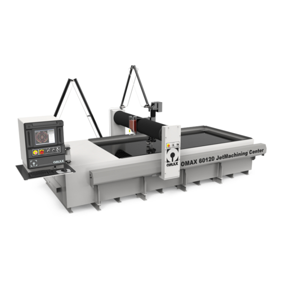
The JetMachining Center is a precision tool that cuts parts out of most materials including metal, plastic, glass, ceramics, stone and composites directly from a CAD drawing or DXF file. Eight versions of the OMAX JetMachining Center are currently available: the models 2626, 2626|xp, 2652, 5555, 55100, 60120, 80160, and 80X. -
Page 30: Pc Controller
Software for the JetMachining Center runs on a personal computer mounted inside the controller cabinet. When supplied with your OMAX, it is already configured and ready to run upon installation. This personal computer is accessible by lifting up the computer access panel. The controller’s hinged arm allows you to position the cabinet according to your viewing requirements. -
Page 31: Control Panel Switches
X-Y Table The X-Y table on OMAX models 2626, 2626|xp, 2652, 5555, and 55100 consists of a bridge X-axis and a cantilever Y-axis rigidly mounted to the cutting table. A series of steel slats provide vertical support for the parts being machined. -
Page 32: Accessories For The Omax Jetmachining Center
Figure 2-13: The OMAX 80X JetMachining Center Accessories for the OMAX JetMachining Center A number of optional accessories are available for your OMAX JetMachining Center. For current prices and ordering information, contact your OMAX distributor. For a complete list of OMAX accessories refer to http://www.omax.com/accessories.php. -
Page 33: Precision Optical Locator
Z-axis to precisely determine the position of a piece of material and enabling secondary machining operations. Figure 2-15: OMAX Precision Optical Locator Waterjet Brick The waterjet brick replaces the normal tank slats to better support thin materials, prevents small parts from falling into the tank, and reduces back splash on materials being cut. -
Page 34: Solids Removal System
This optional garnet removal system automatically removes the garnet and kerf material from the tank, reducing the downtime necessary for manual removal. Figure 2-17: OMAX Solids Removal System Chiller High-pressure pumps last longer when the inlet water temperature is always kept less than 70° F (21°... -
Page 35: Drill Head Attachment
Closed Loop Water Recycling System This closed loop system recycles waste water so that only a small amount of water is needed when operating the OMAX. This reduces the load on the water drain system, and also helps maintains water quality. -
Page 36: Terrain Follower
The Terrain Follower can be retrofitted to any OMAX JetMachining Center having a motorized Z-axis or Tilt- A-Jet. It attaches directly to the machine’s Z-axis and uses a sensing foot that maintains contact with the surface of a material as it's being cut. -
Page 37: Operation
Note: This manual does not provide detailed information on the operation of the OMAX Make and Layout software. For instructions on using this software, refer to the OMAX Interactive Reference (the software help screens), and software training videos available on the OMAX web site at http://www.omax.com/... -
Page 38: Stopping The Pump
Note: If the pump is connected to an OMAX JetMachining Center, pushing the emergency stop switch in at any time (either the emergency stop switch on the pump itself, or the emergency stop switch on the JetMachining Center) immediately shuts down both the pump and the JetMachining Center. -
Page 39: Pump Operating Characteristics
Operation OMAX JetMachining® Center Operator’s Guide 3. The pump control has a “Low PreSet” RPM mode for low pressure operations with the OMAX JetMachining Center. This is useful for piercing brittle materials or etching and scribing materials at reduced pressure. -
Page 40: Figure 3-1: The Abrasivejet Nozzle
OMAX JetMachining® Center Operator’s Guide Operation high-pressure water orfice assembly/jewel abrasive feed tube mixing tube Figure 3-1: The Abrasivejet Nozzle WARNING! Keep your hands away from the nozzle whenever it is moving or cutting. The abrasivejet’s high-pressure stream can cause serious injury. In addition, nozzle movement can crush fingers and hands caught between it and another object. -
Page 41: The Omax Software
Figure 3-2: The Abrasive Waterjet System The OMAX Software OMAX software is used to create part drawings (OMAX Layout) and to cut the part (OMAX Make). The OMAX software completely controls the operation of the JetMachining Center. In addition to OMAX Layout and Make, many other useful utilities are supplied with your OMAX software. -
Page 42: Drawing The Part Using Layout
OMAX JetMachining® Center Operator’s Guide Operation Drawing the Part Using Layout The Layout software is a drawing program that creates parts using lines, arcs, and shapes such as for rectangles and circles. Once drawn, a cutting speed (quality) is assigned to each segment of the drawing. -
Page 43: Using Tabs For Holding Small Parts
When cutting small parts, design them using small holding tabs that prevent the part from detaching and slipping past the slats and down into the tank. Slats in the OMAX are spaced 1" (2.5 cm) apart. Small parts can easily slip between these slats once cut free. Designing tabs to hold a part to the cutting material prevents this. -
Page 44: Ensuring Clean And Quiet Machining
Place a Muff on the Abrasivejet Nozzle The OMAX is shipped with a sponge muff that fits over the abrasivejet nozzle. This muff serves several purposes. It keeps the noise level low during machining, reduces splashing and spraying, and protects the Z-axis and cutting head components. -
Page 45: Tips For Effective Cutting
• Raise the nozzle before running Auto Home If your OMAX machine is equipped with X- and Y-axis hard stops, you can use the Auto Home feature to automatically set the home position. Before you do this, make sure you raise the nozzle high enough to avoid hitting anything (such as fixturing). -
Page 46: Setting Soft Limits
• The top surface may be used for tooling The top surface of the OMAX frame is flat and is exactly parallel to the X and Y motion of the abrasivejet nozzle. This surface may be used for any special fixturing installed. -
Page 47: Operating The Jetmachining Center
Your OMAX should now be accurately aligned and ready for use. Operating the JetMachining Center Note: The following guidelines for operating the JetMachining Center assume that the OMAX operator has received the factory training provided as part of the original equipment purchase and installation. Configuring Your Drawing 1. -
Page 48: Cutting Parts
• Render as a Solid to verify the outcome. • Run collision detection and correct any found. 7. Save your final path drawing. Layout automatically saves it as an OMAX .ord file. Note: Consult the OMAX Interactive Reference for a detailed Layout tutorial and any additional drawing information. -
Page 49: Figure 3-8: White Water Tank Location In Omax Pump
Changing the nozzle orifice size also requires adjustment of the dump orifice in the high- pressure water line of the OMAX pump. Correctly matching the orifice size in the nozzle with that in the pump minimizes water pressure difference in the high-pressure plumbing during nozzle Off and On conditions, thus reducing pressure spikes and premature plumbing failures. -
Page 50: Figure 3-9: Verify Correct Mixing Tube Placement
Add or drain tank water as needed. 14. In Windows, click the OMAX Make icon to launch the cutting software. 15. Auto Home the machine to ensure that the machine’s zero (absolute home) position is set (Figure 3-10). -
Page 51: Figure 3-11: Use Setup To Enable The Soft Limits
Operation OMAX JetMachining® Center Operator’s Guide 16. Verify that the soft limits are enabled (Setup/Advanced/Soft Limits - see Figure 3-11): Figure 3-11: Use Setup to Enable the Soft Limits 17. Position the nozzle between two table slats at 1 (.254 cm) to 1.5 inches (3.81 cm) above the water surface. -
Page 52: Figure 3-14: Comparison Of Jet Streams With Different Jewel And Mixing Tube Conditions
OMAX JetMachining® Center Operator’s Guide Operation Note: Always block the abrasive feed tube prior to visually inspecting the jet quality. Air from this tube interferes with the jet stream, making inspection difficult. d. Refer to Figure 3-14 to compare the effect that a damaged orifice and worn mixing tube have on the quality of a nozzle’s jet stream. -
Page 53: Figure 3-16: Nozzle Pressure Test Stop Button
Operation OMAX JetMachining® Center Operator’s Guide During this jet stream test, adjust the pump RPM to develop the desired low-pressure then write down the pump RPM and KSI values from the pump LCD display screen for the low pressure test. -
Page 54: Figure 3-17: Bimba Valve Abrasive Feed Block
Click Setup in Make and select Pump and Nozzle Settings...: Figure 3-18: Setup Menu for Pump and Nozzle Settings b. Correct any values being displayed that differ from those recorded when testing your OMAX machine. Figure 3-19: Settings for Pump and Nozzle... -
Page 55: Configuring The Make Software
When located, clicking the .ord file name opens that drawing in the adjacent preview screen. Note: If your drawing was developed using another PC other than the OMAX PC Controller, unless networked, you must move it to the PC Controller by copying it to a CD, diskette, or USB memory stick. -
Page 56: Cutting The Material
OMAX JetMachining® Center Operator’s Guide Operation 3. If required, also configure the Cut Settings and Pierce/Terrain Follower Settings: Figure 3-22: Cut, Pierce, and Terrain Follower Setting Options Cutting the Material 1. Move the nozzle to an out-of-way area on the table that allows ample working room for the material to be placed and secured to the table. -
Page 57: Shutting Down The Jetmachining Center
On the Z Height display (Figure 3-24), click the 00 button to set the Z coordinates at zero. 6. Conduct a dry run to verify your cutting path: a. Click the Begin Machining button to display the OMAX Path Control window. b. Right-click the Start button to display the options window. -
Page 58: Figure 3-25: Pump And Nozzle Test Options
9. For a Terrain Follower, secure the foot in its Up position using a bungee cord or similar device. 10. Close OMAX Make and all other software applications running on the OMAX PC Controller. 11. Click the Windows Start button and select Shut Down. -
Page 59: Startup Checkoff Sheet
Operation OMAX JetMachining® Center Operator’s Guide Startup Checkoff Sheet Use the following checkoff sheet to ensure that all equipment startup tasks are completed and in the required sequence. For more detailed startup instructions, refer to Cutting Parts, page 3-12. WARNING! Safety First –... -
Page 60: Shutdown Checkoff Sheet
High-pressure pump POWERED OFF. Air supply valve CLOSED (air is off last so Terrain Follower will not drop the Z-axis). Water level air tank DEPRESSURIZED. Main breaker box POWERED OFF. Your OMAX equipment is now properly shutdown. 3 - 24 400433D-EN... -
Page 61: Maintenance
Pump Maintenance WARNING! All pump maintenance activities must be performed by OMAX qualified personnel. Refer to the OMAX Pump Service and Maintenance Guide for more detailed maintenance information. General Power End Maintenance Performed... -
Page 62: Routine Maintenance Schedule
OMAX JetMachining® Center Operator’s Guide Maintenance Note: Whenever extended periods of pump operation at a motor RPM that is less than shown below are anticipated, you should add one additional quart (3 total) of oil to the pump crankcase. Add additional quart of... -
Page 63: Less Frequent Maintenance Schedule
Replace Manifold (P/N 301350) Every 5000 Every 4500 JetMachining Center Maintenance WARNING! All table maintenance activities must be performed by OMAX qualified personnel. Refer to The OMAX JetMachining Center Service and Maintenance Guide for more detailed maintenance information. Table Maintenance Schedule Activity... -
Page 64: Rebuilding The Nozzle
Refer to the nozzle configuration documentation provided with your OMAX JetMachining Center. These documents contain part numbers needed for ordering replacement or spare parts. Additional documents may be ordered by contacting OMAX Customer Support. Most documents can be downloaded from the OMAX web site (http://www.omax.com) from the Technical Support page. - Page 65 JetMachining Center Operator’s Guide (this document) Nozzle Rebuild DVD Note: Refer to the applicable Nozzle Assembly Drawing for specific OMAX tool part numbers. After preparing your work space and obtaining the necessary nozzle documentation and tools, prepare the OMAX machine for nozzle removal as follows: 1.
-
Page 66: Removing The Nozzle Mixing Tube
OMAX JetMachining® Center Operator’s Guide Maintenance Removing the Nozzle Mixing Tube 1. Remove the abrasive hose from the nozzle. nozzle abrasive hose Figure 4-2: Remove the Abrasive Hose from the Nozzle 2. Place a piece of cardboard or equivalent blocking material directly under the nozzle to prevent any dropped parts or tools from falling into the tank during servicing. -
Page 67: Removing The Filter Seal Assembly From The Inlet Body
Maintenance OMAX JetMachining® Center Operator’s Guide 1/2" wrench on inlet body 1" open-end nozzle body Figure 4-4: Removing the Nozzle Body from the Inlet Body 3. Unscrew the loosened nozzle body by hand and place in your working area for cleaning and disassembly. -
Page 68: Removing The Mixing Chamber Disc
OMAX JetMachining® Center Operator’s Guide Maintenance Removing the Mixing Chamber Disc The mixing chamber disc sits directly beneath the orifice assembly. To remove the mixing chamber disc, gently strike the nozzle body onto the palm of your hand, forcing the disc to release from the nozzle body. -
Page 69: Removing The Nozzle Body O-Ring
Maintenance OMAX JetMachining® Center Operator’s Guide Removing the Nozzle Body O-Ring O-rings should be removed for inspection and replaced during the nozzle rebuild when necessary. 1. Remove the o-ring from the nozzle body. nozzle body o-ring Figure 4-9: Removing the O-ring from the Nozzle Body 2. -
Page 70: Figure 4-11: Cleaning Parts In Ultrasonic Cleaner With White Vinegar
OMAX JetMachining® Center Operator’s Guide Maintenance 5. Clean the orifice or jewel assembly using an ultrasonic cleaner filled with white vinegar. Figure 4-11: Cleaning Parts in Ultrasonic Cleaner with White Vinegar Caution: Use of any damaged or defective nozzle component will negatively impact performance of your OMAX abrasivejet. -
Page 71: Figure 4-14: Chipped Orifice Assembly Jewel
Diamond orifices are highly resistant to chipping from particle impact and have a much longer wear life. Additional jewels may be purchased from OMAX’s Customer Service. Mixing Chamber Disc The mixing chamber disc (Figure 4-12) is also a consumable item requiring close inspection. -
Page 72: Figure 4-16: Worn Mixing Chamber Discs
OMAX JetMachining® Center Operator’s Guide Maintenance As the hole in the mixing chamber disc wears, the probability that garnet can travel above the orifice increases, resulting in a chipped orifice. When a mixing chamber hole is no longer round, it indicates uneven wear. -
Page 73: Figure 4-18: Pump And Nozzle Test Options
OMAX JetMachining® Center Operator’s Guide If the mixing tube is clogged, try to dislodge the blockage as follows: 1. From OMAX’s Make software, click the Test button to display the Test Pump and Nozzle options: Figure 4-18: Pump and Nozzle Test Options 2. -
Page 74: Reassembling The Nozzle Assembly
OMAX JetMachining® Center Operator’s Guide Maintenance Mixing Chamber The mixing chamber is an infrequent consumable item but may need to be replaced if the internal diameter of the mixing chamber hole has grown larger than 0.026" (0.66 mm) or if it shows excessive oblong wear. -
Page 75: Mixing Chamber
Maintenance OMAX JetMachining® Center Operator’s Guide 4. Push the filter with o-ring installed up into the inlet body. filter installed in inlet body Figure 4-23: Filter Seal Assembly Inserted into Inlet Body Note: The nozzle filter seal assembly will be properly seated when the nozzle body is tightened. -
Page 76: Mixing Chamber Disc And Orifice Assembly
OMAX JetMachining® Center Operator’s Guide Maintenance Mixing Chamber Disc and Orifice Assembly 1. Install an O-ring onto the nozzle body. o-ring installed on nozzle body Figure 4-26: Installing the O-ring on the Nozzle Body Caution: Ensure that the nozzle body, the mixing chamber disc, and the mixing chamber surfaces are clean and contamination free. -
Page 77: Nozzle Body
Maintenance OMAX JetMachining® Center Operator’s Guide Nozzle Body 1. Apply a light coating of Blue Goop to the male threads of the nozzle body inlet. Blue Goop nozzle body inlet Figure 4-29: Applying Blue Goop to the Nozzle Body Inlet Threads 2. -
Page 78: Figure 4-32: Damage Caused By An Off-Center Orifice
OMAX JetMachining® Center Operator’s Guide Maintenance check to see if the orifice assembly is still seated in the bore). Refer to Figure 4-32 for an example of an orifice that had been tightened several times while off-center and not correctly seated in its bore. -
Page 79: Mixing Tube
Maintenance OMAX JetMachining® Center Operator’s Guide Caution: The nozzle body uses a soft filter seal, not a high-pressure metal-to-metal seal. If it leaks, check the seal and change it if necessary. Over-tightening will not fix a leak and most likely creates additional repair issues. -
Page 80: Nozzle Tests
• If the quality of the cut part is not as expected, prompt correction of the problem minimizes complications. • Take advantage of features in the OMAX Make software that allow the using of different offset values and mixing tube diameters to adjust for Mixing Tube wear. -
Page 81: Figure 4-38: Abrasive Damage From Not Using A Nozzle Muff
Maintenance OMAX JetMachining® Center Operator’s Guide • Consider using a diamond orifice assembly if orifice chipping is a chronic problem not overcome by using filters or by following proper procedures. • Depending on your application, and if speed and longer life are the primary concern, use a 0.042"... -
Page 82: Removing And Reinstalling The Inlet Body On A Tilt-A-Jet
OMAX JetMachining® Center Operator’s Guide Maintenance Removing and Reinstalling the Inlet Body on a Tilt-A-Jet The inlet body is an infrequent consumable item; however, because it cycles between 0 Psi and 55 Ksi with every on/off cycle, it eventually can wear or crack. -
Page 83: Figure 4-42: Removing The 5Mm Allen Screws That Secure The On/Off Valve Body
Maintenance OMAX JetMachining® Center Operator’s Guide 4. Using a 5 mm Allen wrench and following a continual pattern, loosen the four screws that secure the on/off valve body to the tilting plate (loosen each screw using a ¼ to ½ turn at a time until all screws are loose). -
Page 84: Removing A Stuck Inlet Body
OMAX JetMachining® Center Operator’s Guide Maintenance Removing a Stuck Inlet Body 1. To remove a stuck inlet body, insert the inlet body removal tool post (thread side down) up into the inlet body. inlet body body removal tool post Figure 4-45: Installing the Body Removal Tool Post to Remove a Stuck Inlet Body 2. -
Page 85: Cleaning The Inlet Body
Maintenance OMAX JetMachining® Center Operator’s Guide 4. Saturate the area with white vinegar where the inlet body contacts the tilting plate to help break down water deposits that have bonded the inlet body to the tilting plate. Allow the vinegar to soak for at least 15 minutes. -
Page 86: Reinstalling The Inlet Body
OMAX JetMachining® Center Operator’s Guide Maintenance Reinstalling the Inlet Body 1. Apply a light coating of Blue Goop to the male threads of the inlet body and to the bore diameter around the inlet cone to minimize water deposit buildup around the inlet body. -
Page 87: Figure 4-54: Correct Placement Of The Valve Body Seat Into The Valve Body
Maintenance OMAX JetMachining® Center Operator’s Guide 5. Insert the valve body seat into the on/off valve body with the small hole end inward and the large hole end pointing outward (see Figure 4-54). valve body valve body seat large hole... -
Page 88: Removing And Reinstalling A Mini-Maxjet 5 Nozzle Assembly
OMAX JetMachining® Center Operator’s Guide Maintenance valve body adapter fitting 3/4" open-end high-pressure coil 5/8" open-end on gland nut Figure 4-57: Tightening the Coil Nipple to the On/Off Valve Body Adapter Fitting Caution: Be careful not to allow torque to twist the high-pressure coil as you tighten. -
Page 89: Step 2: Remove The Minijet Nozzle Body From The Inlet Body Extension
Maintenance OMAX JetMachining® Center Operator’s Guide Step 9: Remove the O-Rings and Ring Seals (page 4-31) Step 10: Clean the Nozzle Components Step 11: Inspect the Nozzle Components Step 2: Remove the MiniJet Nozzle Body from the Inlet Body Extension The MiniJet nozzle assembly has an inlet body extension component that is attached between the nozzle body and the inlet body and requires removal. -
Page 90: Step 4: Remove The Minijet Dummy Orifice From The Inlet Body
OMAX JetMachining® Center Operator’s Guide Maintenance Note: The Inlet body extension is a consumable item; however, it is expected to last through multiple nozzle rebuilds. 3. Inspect the surface on each end of the bore on the inlet body extension for erosion marks. If there are erosion signs, the ring seal(s) may leak, requiring that the inlet body extension be replaced. -
Page 91: Step 9: Remove Ring Seals And O-Rings
Maintenance OMAX JetMachining® Center Operator’s Guide Step 9: Remove Ring Seals and O-Rings All ring seals and o-rings should be removed and replaced as needed during a nozzle rebuild. 1. Remove the o-ring from the MiniJet nozzle body. 2. Remove the o-rings and ring seals from the Inlet body extension. -
Page 92: Figure 4-66: Tightening The Inlet Body Extension To The Inlet Body
OMAX JetMachining® Center Operator’s Guide Maintenance 7. Place a 1/2" wrench on the inlet body at the top of the nozzle assembly to hold the inlet body in place and counteract any induced torque when installing the inlet body extension. This prevents any induced torque from affecting the Tilt-A-Jet’s alignment and accuracy. -
Page 93: Mini-Maxjet 5 Installation And Operation
OMAX Technical Support. Note: OMAX recommends using a 120–150 mesh garnet with the Mini-MAXJET 5 nozzle. To avoid plugging the nozzle, never use 80 mesh or coarser garnet. 1. Calibrate the actual abrasive flow rate (refer to Measure the abrasive flow rate:, page 3-17). -
Page 94: Dump Orifice Maintenance
OMAX JetMachining® Center Operator’s Guide Maintenance 3. Correct any values being displayed that differ from those recorded when testing your OMAX machine. Change the “Abrasive Flow Rate” to the value you determined above (if calibration is not done, enter 0.3). Set the “Jewel (orifice) Diameter” to 0.010", the “Mixing Tube Diameter” to 0.021", and the “High Pressure”... -
Page 95: Setting The Adjustable Dump Orifice (Ado)
• Last chance filter not being replaced as recommended to protect the cutting head orifice. Two types of dump orifices are used in OMAX pumps (Figure 4-73): either a dump valve with a fixed, replaceable orifice, or a dump valve having an adjustable dump orifice (ADO). -
Page 96: Figure 4-75: The Ado Pressure Adjustment Knob
Excessive tightening of the ADO knob may jam the valve stem into its seat. If resistance is met while closing the valve, stop tightening! 4. Launch the OMAX Make software and position the nozzle to accommodate a high-pressure, water- only test. -
Page 97: Figure 4-77: Click The Nozzle Test Button To Set Pump Pressure
Maintenance OMAX JetMachining® Center Operator’s Guide 6. Click OK to open the selected ORD file: nozzle Test button Begin Machining button Figure 4-77: Click the Nozzle Test Button to Set Pump Pressure 7. Click the Test button to view the Test Pump and Nozzle window options: Figure 4-78: The Test Pump and Nozzle Window 8. -
Page 98: Figure 4-79: Set The Ksi For Waterpres On The Pump's Lcd
The pump should never be running while the ADO pressure adjustment knob is not securely screwed in place. 15. Once the correct pressure is set, click the Pause button in the OMAX Path Control window (Figure 4- 81) followed by clicking Close. -
Page 99: Changing The Dump Valve Orifice Size
Maintenance OMAX JetMachining® Center Operator’s Guide 16. Replace all removed pump panels and close the pump lid. 17. Adjustment of the ADO pressure is complete. Note: The ADO pressure will require readjusting anytime a different sized orifice is installed in the nozzle, or a defective or worn jewel is replaced with a new one. -
Page 100: Figure 4-84: Loosening The Gland Nut On The Dual On/Off Valve
OMAX JetMachining® Center Operator’s Guide Maintenance 4. Remove the red air hose from the brass air fitting located at the top of the dump valve assembly (Figure 4-83). 5. From the dump valve, loosen the high-pressure tubing gland nut by placing a 13/16" open-end wrench on the gland nut and a 1"... -
Page 101: Figure 4-87: Removing The Valve Assembly From The Dump Valve Body
Maintenance OMAX JetMachining® Center Operator’s Guide 9. Grasp the top of the dump valve assembly and, using a 1.5" open-end wrench on the body assembly nut and a 1.5" open-end wrench on the bulkhead adapter, unscrew the valve body nut from the bulkhead adapter. -
Page 102: Reassembling The Dump Valve With Replacement Orifice Assembly
OMAX JetMachining® Center Operator’s Guide Maintenance 12. Remove the orifice assembly from the dump valve body: orifice assembly without orifice assembly dump valve body removed orifice assembly Figure 4-90: Removing the Orifice Assembly from the Dump Valve Body Reassembling the Dump Valve With Replacement Orifice Assembly 1. -
Page 103: Software Updates
OMAX machine to make substandard parts. Simply run the installation program for the new software to install it. You can also use the OMAX technical support web site to download “beta” versions of the software. Beta software is software that is still being tested, but may contain useful features. This same support site... -
Page 104: Troubleshooting The Omax Pump
You are encouraged to regularly visit this support web site to stay up-to-date on your OMAX equipment. Troubleshooting the OMAX Pump Use this section to help resolve many of the common problems that can occur while operating the OMAX JetMachining Center. Display Screen Messages All fault messages, except those related specifically to the Variable Frequency Drive (VFD), appear on the keypad display. -
Page 105: Fault Message, "Charging Pump Contactor
Reset button lights. To restart the OMAX pump, the fault causing the message must be cleared and the Reset button on the keypad pressed. If all goes well, the display returns to the same display it had prior to the fault trip, the LED next to the Reset button goes out, and the LED next to the Stop button lights;... -
Page 106: Low Pump Output Pressure
Caution: Do not run the OMAX pump once the pressure at a given RPM for a given nozzle drops more than 2000-4000 psi. Continued operation with damaged check valve seats or failed dynamic seals can result in further damage to components in the pump’s wet-end and may result in higher rebuild costs. -
Page 107: No Keypad Display
No Keypad Display The display on the OMAX pump is blank and none of the red LED’s next to keypad buttons are On. 1. Check that no Emergency Stop Switches are engaged. 2. Check that the On/Off Switch on both the Controller and Pump are in their On positions. -
Page 108: Troubleshooting The Omax Jetmachining Center
This section lists most problems encountered with the OMAX Pump. Possible causes are provided for each problem with the most likely causes listed first. If you continue having a problem with your OMAX pump after following these procedures, contact OMAX Customer Service. - Page 109 Maintenance OMAX JetMachining® Center Operator’s Guide An abrasive other than the Many abrasives do not cut as well as garnet, and the machinability recommended garnet is being used. should be reduced when using these abrasives. It may be necessary to experiment to determine the best settings.
- Page 110 OMAX JetMachining® Center Operator’s Guide Maintenance The standoff between the abrasivejet The standoff should be no more than 0.050" (1.3 mm) for best results. nozzle and the material is excessive. Note: 0.060" (1.52 mm) is generally recommended, especially with the Tilt-A-Jet option. Typically, lower standoff distances decrease the amount of taper, but a lower standoff increase the likelihood of nozzle plugging.
- Page 111 Maintenance OMAX JetMachining® Center Operator’s Guide Abrasivejet Not Piercing Material Condition and Possible Causes Corrective Action Setup values entered in Make are not Check that the material setup values for the following parameters are consistent with the actual physical correctly set in Make: requirements.
-
Page 112: Software Problems
Y-axis whenever: • The X-axis drive motor faults • The Y-axis bridge crashes Software Problems Also refer to the OMAX Interactive Reference (OIR) for help in troubleshooting software problems. Keyboard or Mouse Doesn’t Work Condition and Possible Causes Corrective Action... -
Page 113: Nozzle And Abrasive System
“Babysit Triggered” Message Note: The OMAX has several switches monitoring machine operation. When any of these switches are triggered, the abrasive jet nozzle immediately stops operation and no longer continues machining or is able to be moved. When an attempt is made to restart operation, a “Babysit Triggered”... -
Page 114: Miscellaneous
OMAX JetMachining® Center Operator’s Guide Maintenance The mixing tube is worn and Mixing tube wear occurs first at the inlet, then a conical wear zone unable to form a perfect jet stream grows toward the exit end of the mixing tube. Check the tube bore at both ends using a drill or gage pin. -
Page 115: Positioning Accuracy Overview
OMAX. Positioning Accuracy Overview OMAX Jet Machining Centers specify a positioning accuracy of +/- 0.003" for ball bar circularity (over 12 inches) at maximum velocity and at any table location. In addition, the 2626|xp specifies a positioning accuracy of 0.001"... - Page 116 Verify that the nozzle returned to the exact starting location without loosing steps. Repeat this for both axis. • When convinced that all of the above checks are functioning accurately and the machine’s positioning accuracy remains an issue, contact OMAX Customer Service. 4 - 56 400433D-EN...
-
Page 117: Consumable Parts
Refer to the assembly drawings provided with your OMAX JetMachining Center for part numbers specific to your model. For assistance in ordering consumable parts, contact OMAX Technical Support. - Page 118 Fuse, Time Delay, 250 VAC, 0.5 A, 5mm x 20mm, Glass 201704 These additional items are also recommended to support operation of your OMAX: • Sponges for cleanup • Steel, brass, or lead weights for holding materials in place during machining •...
-
Page 119: Maintenance Log
Maintenance OMAX JetMachining® Center Operator’s Guide Maintenance Log Run Hours Maintenance Performed Done By Date 400433D-EN 4 - 59... -
Page 120: Training Log
OMAX JetMachining® Center Operator’s Guide Maintenance Training Log Date Training Description Trainer Trainee 4 - 60 400433D-EN... -
Page 121: Customer Support
• your shipping information • purchase order number Parts in stock are shipped within 3 working days from receiving the order. When not in stock, OMAX provides an estimated shipment date. Same-day shipments for system-down emergencies can be accommodated if the requested part is in stock and the order received before 12:00 noon, Pacific Time. -
Page 122: Parts Ordered In Error
4. You must issue a new purchase order for any replacement parts. 5. Parts are shipped to you FOB Kent, Washington, USA. 6. If the returned parts are not new, or if OMAX receives them after the 30-day limit, the OMAX Customer Service Coordinator determines their proper disposition. -
Page 123: Parts Shipped In Error
3. If the parts are determined new and are received within the 30-day limit, you receive full credit for the amount charged, and the part originally ordered is shipped. 4. If the returned parts are not new, or are received by OMAX after the 30-day limit, the OMAX Customer Service Coordinator determines the proper disposition. -
Page 124: Two-Year Limited Warranty
OMAX. All labor is the responsibility and expense of the Buyer. The liability of OMAX under this warranty is limited, at OMAX’s exclusive option, solely to repair or replacement with equivalent items or refund of the purchase price upon return of the subject nonconforming Product. -
Page 125: Omax Glossary
The rate at which abrasives are blown through the mixing tube. The abrasive flow rate should be measured for your OMAX machine every couple of weeks, or whenever you change abrasive size or brand. The flow rate is usually measured in Lbs/Min or Kg/Min. Generally speaking, the higher the abrasive flow rate, the faster the cut. - Page 126 Beta Software Beta Software is software that is still in its testing phase, and is not officially released yet. Before OMAX officially releases the software to all OMAX customers, OMAX will release software as “Beta” to a small group of custom- ers for the purpose of final testing.
- Page 127 Burr Burr refers to a rough edge on material that has been machined. On the OMAX, there is only a very slight burr with most materials, which only shows up under extreme magnification. In very thin materials, more burr may be evident.
- Page 128 Cutting quality A term used on OMAX, and sometimes other controllers to indicate how the machine should cut a given surface of the part. A quality of “1” being a very rough, high speed cut, and a quality of “5” being a very smooth, highly precise operation.
- Page 129 A line or arc drawn between these two points • A cutting Quality An entity is the smallest unit used to make up drawings. There are only two basic types of entities in OMAX-- lines and arcs. E-Stop Emergency Stop. Typically a button that you press to stop the machine in the event of an emergency.
- Page 130 OMAX JetMachining® Center Operator’s Guide OMAX Glossary Grid The drawing grid in Layout is the same size as the standard OMAX JetMachining Center machining table. The grid is shown as a series of white squares. Hard Limit A hard limit is a stop on the machine that prevents the machine from moving further in a given direction. Typically...
- Page 131 1 megapascal = 145 PSI 1 megapascal = 10 bar This is commonly used in the United States and is the unit used by OMAX software when you select any of the English units of measurements. KSI = 1,000 PSI 1 PSI = 0.069 bar...
- Page 132 Off-line Programming is the process of drawing parts and making tool paths on a computer that is not connected to an OMAX. This is the preferred method for programming an OMAX because it does not tie up the machine with tasks that you can do on a much less expensive computer.
- Page 133 Pressure is a measure of force against area. Pounds per square inch This is commonly used in the United States and is the unit used by OMAX software when you select any of the English units of measurements. KSI = 1,000 PSI 1 PSI = 0.069 bar...
- Page 134 OMAX JetMachining® Center Operator’s Guide OMAX Glossary PWJ (pure water jet) A pressurized jet of water exiting a small orifice at extreme velocity. Used to cut soft materials such as foam, rub- ber, cloth, paper, etc. See “Waterjet.” Quality Same as “Cutting Quality”.
- Page 135 There is no cure for silicosis -- prevention is the only answer. Slat Stainless steel plates which support the material being machined in the OMAX tank. Slug Slugs are any scrap parts that you remove. One advantage of abrasivejet machining is that the slugs can be valuable for recycling, or for being made into another part on another machine.
- Page 136 OMAX JetMachining® Center Operator’s Guide OMAX Glossary sive materials such as titanium. However, slugs can also pose a collision threat when machining, so care must be taken when planning your tool paths to avoid them. Snap When snap is turned on (with the Enable Snap Grid command), any time you click in your drawing, you will snap to the closest point on the grid.
- Page 137 Tilt-A-Jet (TAJ) represents the latest OMAX innovation in the continuing search for more accurate abrasivejet machining. Tilt-A-Jet lets the OMAX JetMachining Center achieve virtually zero taper with most materials. As the machining nozzle moves along the tool path, Make calculates the amount of taper, and then tilts the machining head to exactly offset the taper from the abrasivejet.
- Page 138 The path that the tool will follow when making a part. The tool path includes traverse information as well as cut- ting information. Tool Path Font A font designed for use with the OMAX. A number of tool path fonts are provided with Layout, including ones optimized for Etch and Scribe machining. Traverse Normal machine movement without cutting, for example to move the cutting head into position to cut.
- Page 139 Water Only Water Only is a type of Quality. OMAX does not use any abrasive for entities with a Quality of Water Only. Water Only is used for machining soft material that can be pierced using only a high-pressure water jet (for example, sponge or foam).
- Page 140 OMAX JetMachining® Center Operator’s Guide OMAX Glossary 6 - 16 400433D-EN...
-
Page 141: Index
OMAX JetMachining® Center Operator’s Guide Index dead head message inlet body 4 -45 4 -4 4 -22 defragmenter removal 4 -3 4 -6 dipstick 4 -2 disc, mixing chamber 4 -11 abrasive feed block 3 -18 jet stream, quality 3 -15... - Page 142 OMAX JetMachining® Center Operator’s Guide manifold filter drill head attachment 4 -35 2 -13 reboot 4 -3 map, sound level MiniJet 1 -7 2 -11 registered trademarks material setup values precision optical locator 3 -19 2 -11 repair, parts 5 -3...
- Page 143 OMAX JetMachining® Center Operator’s Guide Water Only 3 -6 table waterjet brick 2 -11 1 -1 operating 3 -11 WD40 4 -55 safety requirements 1 -5 white vinegar 4 -10 tabs 3 -7 white water tank 3 -12 4 -1...
- Page 144 OMAX JetMachining® Center Operator’s Guide Index - 4 400433D-EN...
Need help?
Do you have a question about the JetMachining Center 2626 and is the answer not in the manual?
Questions and answers