Omax PROTOMAX Manual
Water jet cutter
Hide thumbs
Also See for PROTOMAX:
- Quick installation overview (2 pages) ,
- Operation manual (45 pages)

Related Manuals for Omax PROTOMAX


Summary of Contents for Omax PROTOMAX
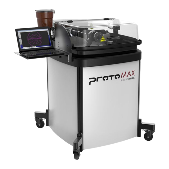
- Page 1 PROTOMAX WATER JET CUTTER Workarea: 300 x 300 mm Max. Thickness: 25mm Possible Materials: Metals, Carbon Fiber, Plastics, etc.
- Page 2 SAFETY ● Never operate equipment without safety guards or covers. ● Never place your hands in the vicinity of the nozzle while cutting. ● Do not make any modifications. ● Safety goggles and rubber gloves mandatory. PAGE 2...
- Page 3 LAYOUT SOFTWARE Importing a file Click on [Import from other CAD] ● to load your file. You will need a .dxf file. After selecting the path to your ● design, a preview is shown. If needed use the checkboxes on the left to modify it.
-
Page 4: Moving Around
LAYOUT SOFTWARE Cleaning the design Click on [Clean] on the toolbar. ● The standard setting should be ● sufficient. Next click [Start]. ● Design size The size of the design can be modified using the [Size] tool on the left. Moving around Using the [Move] tool we move our design close to the lower left corner... -
Page 5: Cut Settings
LAYOUT SOFTWARE Cut settings Everything that should be cut needs to have a cut quality assigned. Press the [Q] button in the bottom and select your desired quality. 3 Should be sufficient. Higher number mean higher quality, so longer processing time and costs. Cut path Now we can create the toolpath using the [Autopath] tool. - Page 6 LAYOUT SOFTWARE Saving the design When you are happy with the preview use the [Post] button on the right. Select the starting point. The point must be an end point. Make sure to always use the point so that the inner parts are cut first.
-
Page 7: Turning On The Machine
TURNING ON THE MACHINE First insert the big power connector that is placed under the table right of the machine into the connector on the wall. The humming noise is normal. Ensure that the plug right, labeled “Pump” is also connected. Next you can turn on the machine using the big red switch on the right side. - Page 8 TURNING ON THE MACHINE Check that both black water valves are in the close position as shown here. If they are closed, you can open the blue valve until the end. An orange ring should be visible. Lift the nozzle so that is it above the metal slats.
- Page 9 MAKE SOFTWARE On start When the machine is turned on it needs to homed. Close the warning window by clicking [Ok]. Click on the red box in the top left corner to start the homing process. REMEMBER: Every time the machine is moving the lid neets to be closed.
- Page 10 MAKE SOFTWARE Units If the unit at the bottom show [inches] use the [Configure Display & Units] option to change it. Similar to before you can easily set the units to “mm”. From the get go you are presented with a sample file.
-
Page 11: Material Settings
MAKE SOFTWARE Material settings Navigate to the location of your file and select it. A preview of the design and path will be displayed. At this point it is important to select the material on the lower left section. Also ensure the material thickness is correct. PAGE... -
Page 12: Preparing The Machine
PREPARING THE MACHINE Filling the vat Using the hose on the right valve fill the machine vat until 1 cm below the metal slats. Ensure that the overrun with the spongy tip on the right is moved all the way up. 1 cm Flushing the machine Next the machine needs to be flushed. - Page 13 PREPARING THE MACHINE Remove the plastic tube from the cutting head and place it on top of the axis so that is can not drop into the water. Release the head unit and move it to about 5 mm above the metal slats using the big black knob.
- Page 14 PREPARING THE MACHINE On the computer click on [Test]. Select the first option and press [Next]. Double check that the abrasive tube is removed and secured, and that the cutting unit is between two slots. Then press [Start Test]. The Test will take 60 seconds and finish automatically.
- Page 15 PREPARING THE MACHINE After the test is done open the door and install the abrasive tube as shown on the picture. Ensure that the tube is completely inserted in the cutting unit. Afterwards follow the same test process as before. As soon as you can see abrasive (sand particles) moving in the tube you can stop the test.
- Page 16 CUTTING With you file loaded click on [Begin Machining]. In the window that shows up right click [Start] Here you have the chance to make a dry run. A dry run is mandatory before any cutting. During the dry run check that there are no collision.
- Page 17 CUTTING If the dry run was successful and you moved to the home position you now need to adjust the cutting unit to the correct height. Use the stand-off tool. The nozzle needs to touch it but you need to still be able to move it away.
- Page 18 CUTTING When the machine is done cutting use the arrow keys to move the cutting unit out of the way. Be careful removing the parts as they are sharp edged. Try not to lose small parts inside of the water. Once more remove the abrasive tube and secure it on top.
- Page 19 CLEANING UP Use water and paper towels to clean the machine. Please do not use cleaning agents. Close all the water valves. Make sure that the blue valve does not show an orange ring. Then turn off the machine and unplug the big power plug.
- Page 20 FILLING UP THE ABRASIVE If the abrasive sand is too little you can fill it up by using the big cup near the waterjet. Only fill up the abrasive sand if is necessary and when the machine is off. PAGE...
Need help?
Do you have a question about the PROTOMAX and is the answer not in the manual?
Questions and answers