Table of Contents
Advertisement
Quick Links
TRUE TEMPERATURE
INDICATOR MODEL TTI 7
PLUS
User Maintenance Manual/Handbook
Isothermal Technology Limited, Pine Grove, Southport, PR9 9AG, England
Tel: +44 (0)1704 543830 Fax: +44 (0)1704 544799 Internet: www.isotech.co.uk E-mail: info@isotech.co.uk
The company is always willing to give technical advice and assistance where appropriate. Equally, because of the programme of continual
development and improvement we reserve the right to amend or alter characteristics and design without prior notice. This publication is for
information only.
Page 1 of 44
TTI-7 Iss.02 – 06/11
Advertisement
Table of Contents

Subscribe to Our Youtube Channel
Related Manuals for Isotech TTI 7 PLUS

Summary of Contents for Isotech TTI 7 PLUS
- Page 1 Isothermal Technology Limited, Pine Grove, Southport, PR9 9AG, England Tel: +44 (0)1704 543830 Fax: +44 (0)1704 544799 Internet: www.isotech.co.uk E-mail: info@isotech.co.uk The company is always willing to give technical advice and assistance where appropriate. Equally, because of the programme of continual development and improvement we reserve the right to amend or alter characteristics and design without prior notice.
-
Page 2: Table Of Contents
CONTENTS GUARANTEE ................................4 EMC INFORMATION ..............................5 ELECTRICAL SAFETY ..............................5 Environmental Ratings ............................5 OPERATING INSTRUCTIONS: SOFTWARE VERSION 7.1 ..................6 SUPPLIED ACCESSORIES ............................6 SAFETY ..................................6 CE MARKING ................................6 INSTALLATION ............................... 6 MAINTENANCE ..............................6 Batteries ................................ - Page 3 Standard Event Registers ............................ 37 Operation Registers............................38 Status Byte Registers ............................39 RS-232 Interface Commands ..........................40 Front Panel Operations ............................40 APPENDIX I: COMMAND SUMMARY ........................41 Programming Language ............................41 Measurement Configuration Commands ......................41 Triggering Commands ............................41 Routing Commands ............................
-
Page 4: Guarantee
INTERFERENCE WITH OR FAILURE TO PROPERLY MAINTAIN THIS INSTRUMENT MAY INVALIDATE THIS GUARANTEE RECOMMENDATION The life of your ISOTECH Instrument will be prolonged if regular maintenance and cleaning to remove general dust and debris is carried out. We recommend that this instrument to be re-calibrated annually. -
Page 5: Emc Information
The Blue conductor should be connected to Neutral and the Brown conductor to Live (Line). Warning: Internal mains voltage hazard. Do not remove the panels. There are no user serviceable parts inside. Contact your nearest Isotech agent for repair. Voltage transients on the supply must not exceed 2.5kV. -
Page 6: Operating Instructions: Software Version 7.1
OPERATING INSTRUCTIONS: SOFTWARE VERSION 7.1 SUPPLIED ACCESSORIES 1 Mains Cord 1 RS 232 Cable 1 Operating Instructions (English) When unpacked, inspect for physical damage and report any defects immediately in writing, retaining packaging materials for inspection. Before placing into service, ensure mains voltage is correct. Instruments are normally supplied for 240Volts 50Hz. -
Page 7: Batteries
CAUTION: Disconnect the mains lead and all connecting leads, before removing the fuse holder. Replace only with the correct fuse type, i.e. according to the following chart. LINE Range Fuse (250V) VOLTAGE IEC 127 Selection 47-63Hz 5 x 20 mm 100V 90-110V} 630mA (T) -
Page 8: Uncertainty Of Measurement
UNCERTAINTY OF MEASUREMENT SENSOR RANGE °C RESISTANCE CURRENT RESOLUTION °C, °F, UNCERTAINTY @ 20°C ±5°C Pt25 -200 to -100 2.5 to 15 1 mA 0.001 0.02 °C Pt25 -100 to +500 15 to 75 1 mA 0.001 0.01 °C Pt25 +500 to +670 75 to 115 1 mA... -
Page 9: General
TEMPERATURE: STORAGE -20…+55°C TEMPERATURE: MAINS SUPPLY: 100/120/220/240 Volts +10% -13% 47…63Hz. 80VA DATA LOGGING: Up to 4000 single channel values may be stored with date and time. MATHS: Computes Max/Min values, Mean values, peak to Peak values, and standard deviation. Values all computed from values stored in log. - Page 10 DISPLAY CONTRAST: To change this display contrast, press and hold down either the ↑ or ↓ key; the contrast will vary and may be selected for optimum viewing. The contrast and the viewing angle are changeable, and it may be desirable to alter the contrast from time to time as your reading position alters. selects channel A to the display Selects channel B to the display Displays the difference between probe A and probe B...
- Page 11 To configure the input for PRT input from the SENS screen, select PRT. Select EN-60751 to select the Industrial PRT standard linearisation for Pt100, the coefficients may be reviewed by pressing the Rev Key but cannot be changed. To select other coefficients and to configure for Pt25 press the User key. Enter the probe number and press OK if the probe number selected has already been configured, then press Quit to return to the main measurement menu.
- Page 12 Once a probe has been configured it can be recalled from the SENS menu and reconfigured if required using the Rev option. AN IMPORTANT feature of the TTI 7 PLUS is that each channel may be configured with any sensor type so that RTD’s may be compared against thermocouples.
- Page 13 To select a scanning list pres SL1 to SL4, to turn off the scanning press Off. With the scanning list selected it is now possible to edit the list press the Edt key The channels included in the scanning sequence can now be selected by pressing the Add key or deleted with the Del key;...
-
Page 14: Data Logging
Data Logging To configure the data logging from the main measurement screen select SCAN and Mem To set up a new log press New confirm that you wish to clear the current log and then press On to activate the logging function press OK to confirm and Quit to return to measurement screen. - Page 15 This selects the measuring current in the negative direction. Measuring time is approx. 1.8 seconds per reading for channels A and B, and 3 seconds for A-B. This automatically switches the measuring current from forward to reverse direction and displays the average of the 2 readings, thus eliminating any errors due to thermal emf.
-
Page 16: Rtd Inputs
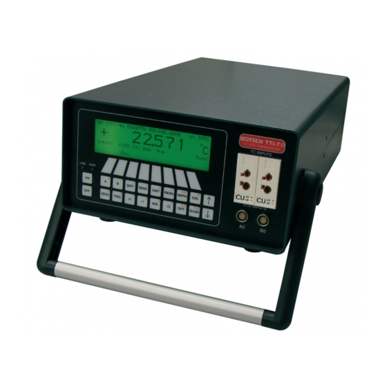
RTD INPUTS There are 2 LEMO sockets for the Pt100 inputs and the connections are as figure below. For the best performance we recommend 4 wire sensors, but the thermometers are able to measure with 2, 3, and 4 wire sensors. TTI 7 PLUS The sensors may be plugged into either channel A or B. -
Page 17: Calibration
PLUS CAUTION: When measuring thermocouples with the TTI 7 it should be remembered that the temperature may be read to 0.01C, and this is equivalent to approximately 0.4V per digit with a type K thermocouple. Care must therefore be taken to avoid exposing the instrument inputs to draughts or a heat source such as sun shining on the front panel. -
Page 18: Rj Calibration
Isotech will continue to develop new instruments and to update the design of existing models and, therefore, will be able to offer an instrument suitable for your needs. -
Page 19: Cal Notepad
CAL NOTEPAD The models are supplied with Cal NotePad as standard. This easy to use package is compatible with MS Windows 9x. A handbook for Cal NotePad can be found on the first installation disk in Adobe PDF format. If required a free Adobe PDF reader can be downloaded from, www.adobe.com. -
Page 20: Starting Cal Notepad
STARTING CAL NOTEPAD From a Standard Installation: Click the START button Highlight PROGRAMS Select Isotech - Select Calpad PLUS Note: Ensure the the TTI 7 is switched on and connected to the PC before starting the software. Configuring for the TTI 7 PLUS From File –... -
Page 21: Remote Control Interfaces
REMOTE CONTROL INTERFACES INTRODUCTION Version History Ver 7.1 (ECN 253) DATAlogger:CLEAr command corrected to DATAlogger:CLEar. Both versions will be accepted to maintain backward compatability. Ver 7.0 (ECN 239) added Type ‘L’, ‘U’ & AuPt thermocouples, SPRT probes and Pt25 probes. The obsolete IEC751 and US/JIS standards for resistance to temperature conversion were deleted. -
Page 22: Front Panel Set Up
Always use a time delay between transmitted characters, or better still, use the full 5-wire connection for reliable hardware handshaking of each character. It is recommended that Isotech cable be used for connecting the instrument to a PC. This has the 5-wire connection and will maintain EMC integrity. -
Page 23: Programming The Interface
PROGRAMMING THE INTERFACE Introduction All interfaces are programmed in a common language which is based on SCPI (Standard Commands for Programmable Instruments). Although similar in style, full conformance to the SCPI and IEEE488.2 standards is not guaranteed. The following is a brief guide to the structure and syntax of the programming language. Command Tree Commands are arranged as a hierarchical “tree”, similar to the filing system trees found in personal computers. -
Page 24: Data Types
Command Syntax Most command keywords have both a long and short form. The bus controller can send commands in either form and also in any combination of upper and lower case characters. Instrument responses, however, are always in the short form, upper case. Data Types The bus controller can also send data in a range of formats, but the instrument always responds in a precise format. -
Page 25: Input Buffer
Input Buffer The instrument receives messages into an input buffer and only starts executing commands after receipt of a message terminator. The buffer can store up to 100 characters including separators and terminator. Sending a new command before the existing command is executed may cause unreliable operation. It is advisable to query the Status Byte (*STB) to check on the current status of the instrument before sending a new command. - Page 26 CONFigure:TEMPerature:RTD <type>,<standard>,<con>,<current mode>,<root 2> Sets the selected channel for an RTD measurement according to the following parameters. type < > Pt25, Pt100 standard < > Invalid (Obsolete) Invalid (Obsolete) (EN60751) 4-23 (User Probe 1-20) < > 3, 4 (3 or 4 wire connectivity) current mode <...
-
Page 27: Triggering Commands
SENSe:TEMPerature:RESolution? Queries the temperature resolution. Responds with 1, 0.1, 0.01 or 0.001. Triggering Commands The TRIGger and SAMPle commands are used to control the instrument’s scanner operation, and to configure the scanning lists. INITiate The current measurement cycle and scanning routine is terminated and a new single measurement is made. The Measurement Available bit (8) of the Operation Condition Register is set on completion. - Page 28 Returns the Rolling Mean or Standard Deviation of the resistance of the RTD probe in Ohms. The resolution of the Mean is normally 0.001, but this is increased to 0.0001 if a Pt25 probe is being used, and the temperature resolution is set to the highest (0.001).
- Page 29 The TRIGger:COUNt? <slx> command queries the specified scanning list timer cycle count. <slx> SL1, SL2, SL3, SL4 Specify scan list Returns the cycle count value (1 to 9999), or “CONT”, if the value is continuous. TRIGger:DELay <hh:mm:ss> TRIGger:DELay <slx>, <hh:mm:ss> The TRIGger:DELay <hh:mm:ss>...
-
Page 30: Routing Commands
SAMPle:DELay? <slx> Queries the specified scanning list timer sample delay. <slx> SL1, SL2, SL3, SL4 Specify scan list Returns the delay time (00:00:00 to 99:59:59). Routing Commands ROUTe:SCAN:LSELect <slx> This command is used to set the scanner mode, and to select the scan list. The scanner is enabled by selecting a scanning list. -
Page 31: Datalogger Commands
For a user memory with no coefficients stored: User no ”USER < .>:” “EMPTY” For a user memory with IPRT (CvD) coefficients stored: User no ”USER < .>:” ”TYPE: <PT25 / PT100>” “CONV: IPRT” R0 value “R0: < >” A coefficient value “A: <... -
Page 32: Mathematical Operation Commands
DATAlogger:STOP Forces the trigger-hold mode, and terminates the current measurement cycle. DATAlogger:STARt or DATAlogger:STEP commands can be used to continue the log from this point. This command is only active when DATAlogger:MODE is ON. DATAlogger:STEP Forces the trigger-single mode and takes a single measurement only, which is stored in the next datalog location. The command can be used to step through a scanner routine, saving the results in the data logger memory. -
Page 33: Autozero And Rolling Mean & Standard Deviation Commands
Autozero And Rolling Mean & Standard Deviation Commands <off/on SENSe:ZERO:AUTO > Turns the autozero function off/on. The ‘on’ mode is automatically reset to ‘off’ if any of the following commands is sent: type>,<rj mode>,<ext rj standard> CONFigure:TEMPerature:TC < type>,<standard>,<con>,<current mode>,<root 2> CONFigure:TEMPerature:RTD <... - Page 34 off/on SYSTem:BEEPer:STATe < > Disable or enable the front-panel beeper. SYSTem:BEEPer:STATe? Query the state of the front-panel beeper. Returns “0” (OFF) or “1” (ON). SYSTem:VERSion? Query the SCPI version to which the instrument conforms. The instrument series is not compliant and returns the message “NOT SCPI COMPLIANT”.
-
Page 35: Status Reporting Commands
Status Reporting Commands There are five groups of registers involved. The Questionable Data and Operation groups each consist of three registers: The Condition Register contains the current status of the instrument and is continuously updated. The register value can be read at any time using the appropriate query (?) command. The Event Register detects ‘0’... - Page 36 The Status Reporting System is summarised in the following diagram. Questionable Data R e g C o n d i t i o n E v e n t E n a b l e B i t R e g i s t e r R e g R e g T e m p e r a t u r e R a n g e...
-
Page 37: Questionable Data Registers
Only a few status bits are used in the instrument, and this reporting system may look a little unwieldy at first. However, it follows the style of SCPI and the unused bits are allocated to other functions which allow for expansion and compatibility with other SCPI compliant devices. -
Page 38: Operation Registers
*ESE <enable value> Enables bits in the Standard Event Enable Register. The selected bits are then reported to the Status Byte. *ESE? Queries the Standard Event Enable Register. The instrument returns a decimal value which corresponds to the binary-weighted sum of all bits set in the register. *OPC This command sets the instrument’s ‘Operation Complete Command State’... -
Page 39: Status Byte Registers
Status Byte Registers The Status Byte Register contains summary bits from the Questionable Data, Standard Event and Operation Registers, and also has a single bit reporting the Service Request function for IEEE. The Service Request function allows the instrument to request service from the system controller. If the same bit is set simultaneously in both the Status Byte Register and the Service Request Enable Register, the RQS bit is set in the Status Byte Register and the SRQ (service request) bus signal is asserted. -
Page 40: Rs-232 Interface Commands
*SRE <enable value> Enables bits in the Service Request Enable Register. The selected bits are then reported to the Status Byte. *SRE? Queries the Service Request Enable Register. The instrument returns a decimal value which corresponds to the binary-weighted sum of all bits set in the register. *CLS Clears the Status Byte Summary Register and all event registers, and also resets the Operation Complete Command State and Operation Complete Query State. -
Page 41: Appendix I: Command Summary
APPENDIX I: COMMAND SUMMARY Programming Language All interfaces use the same commands. For the RS-232 interface these commands are sent as part of a serial string. For the IEEE-488 interface these commands are sent as a Multi-wire Interface Message (with ATN=High). Measurement Configuration Commands CONFigure channel>... -
Page 42: Routing Commands
Routing Commands ROUTe: SCAN:LSELect <slx> SCAN:LSELect? SCAN:INTernal <slx>, <scanlist> SCAN:INTernal? <slx> Memory Commands MEMory user probe number :COEFficient? < | ALL> Datalogger Commands DATAlogger off/on :MODE < > :MODE? :CLEar :STARt :STOP :STEP value/all :VALue? < > :POINts? Mathematical Operation Commands CALCulate :AVERage:MINimum? :AVERage:MAXimum? -
Page 43: Status Reporting Commands
SYSTem hh,mm,ss :TIME < > :TIME? format :DATE:FORMat < > :DATE:FORMat? dd,mm,yy mm,dd,yy :DATE < > or < > :DATE? *IDN? *RST *TST? *WAI Status Reporting Commands STATus :QUEStionable:CONDition? :QUEStionable:EVENt? enable value :QUEStionable:ENABle < > :QUEStionable:ENABle? *ESR? *ESE <enable value> *ESE? *OPC STATus... -
Page 44: Appendix Ii: Rs-232 Pin Connections
APPENDIX II: RS-232 PIN CONNECTIONS Data Carrier Detect (not connected) Received Data (input) Transmitted Data (output) Data Terminal Ready (not connected) GND Signal Ground Data Set Ready (not connected) Request To Send (output) Clear To Send (input) Ring Indicator (not connected) Page 44 of 44 TTI-7 Iss.02 –...
Need help?
Do you have a question about the TTI 7 PLUS and is the answer not in the manual?
Questions and answers