Bosch MIC inteox 7100i Installation Manual
Hide thumbs
Also See for MIC inteox 7100i:
- User manual (96 pages) ,
- Installation manual (72 pages) ,
- Instruction manual (72 pages)
Table of Contents
Advertisement
Quick Links
Advertisement
Table of Contents

Related Manuals for Bosch MIC inteox 7100i


Summary of Contents for Bosch MIC inteox 7100i
- Page 1 MIC inteox 7100i Installation Manual...
-
Page 3: Table Of Contents
13.2 Power Source Options 13.3 Ethernet Connections 13.4 Camera Connections Troubleshooting 14.1 Physical reset button Maintenance Disposal Technical data Best Practices for Outdoor Installation Status Codes Support services and Bosch Academy Bosch Security Systems 2021-03 | 1.2 | Installation Manual... -
Page 4: Safety
Legal Information Copyright This manual is the intellectual property of Bosch Security Systems, and is protected by copyright. All rights reserved. Trademarks All hardware and software product names used in this document are likely to be registered trademarks and must be treated accordingly. -
Page 5: Safety Precautions
MIC inteox 7100i Safety | en Safety Precautions In this manual, the following symbols and notations are used to draw attention to special situations: Danger! High risk: This symbol indicates an imminently hazardous situation such as “Dangerous Voltage” inside the product. If not avoided, this will result in an electrical shock, serious bodily injury, or death. - Page 6 | Safety MIC inteox 7100i 2021-03 | 1.2 | Bosch Security Systems Installation Manual...
-
Page 7: Customer Support And Service
MIC inteox 7100i Safety | en Customer Support and Service If this unit needs service, contact the nearest Bosch Security Systems Service Center for authorization to return and shipping instructions. USA and Canada Telephone: 800-289-0096, option 5 Fax: 800-366-1329 Email: repair@us.bosch.com... -
Page 8: Introduction
Sales or Customer Service Representative from Bosch Security Systems. – Do not use this product if any component appears to be damaged. Please contact Bosch Security Systems in the event of damaged goods. – The original packing carton (if undamaged) is the safest container in which to transport the unit and must be used if returning the unit for service. -
Page 9: Additional Tools
You can also use the Project Assistant app to complete the initial configuration of the camera. In order to use this device with the Project Assistant app by Bosch, you must download the app from the Bosch Download Store, from Google Play, or from the Apple Store. -
Page 10: Product Description
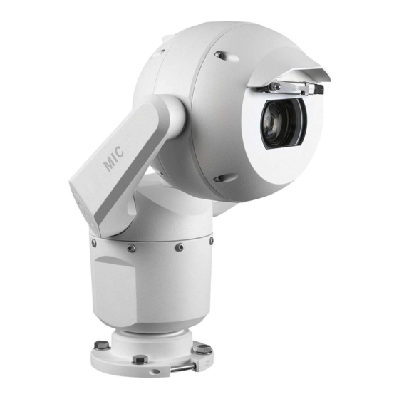
| Product Description MIC inteox 7100i Product Description The camera’s ruggedized design meets customer expectations in demanding environments that exceed the capabilities of conventional IP cameras. Even in installations subject to harsh shock/vibration conditions and/or extreme weather, the camera provides high-quality video images. -
Page 11: Overview Of Installation Steps
® Electrical Code (NEC)), Canadian Electrical Code, Part I (also called CE Code or CSA C22.1), and all applicable local codes. Bosch Security Systems accepts no liability for any damages or losses caused by incorrect or improper installation. Caution! ELECTRIC SHOCK HAZARD... -
Page 12: Mounting
Mounting Mounting Location and Orientation Options Bosch designed MIC IP 7100i cameras for use in outdoor applications. In an enclosed installation area (for example, in a foundry, near a furnace, etc.), temperatures outside of the camera might exceed +65 °C (+149 °F). If you install a camera in an enclosed area, make sure that the operating temperature of the camera is a maximum of +60 °C (+140 °F). -
Page 13: Mounting Options
If the camera is installed in a highly exposed location where lightning strikes may occur, then Bosch recommends installing a separate lightning conductor within 0.5 m (1.6 ft) of the camera and at least 1.5 m (4.9 ft) higher than the camera. A good earth bonding connection to the camera housing itself will provide protection against damage from secondary strikes. - Page 14 | Mounting MIC inteox 7100i MIC cameras are designed to be mounted upright (straight up, 90°), inverted (straight down, 90°), or canted upright (ball up, 35°). The tilt limits for the canted unit prevent it from working properly if mounted ball down. See the figures below for illustrations of the correct and the incorrect mounting orientations of MIC cameras.
-
Page 15: Mounting Bracket Options
Bosch sells a complete series of mounting brackets that support multiple mounting configurations. Always use only Bosch-supplied mounts, which are designed for safe installation of your MIC camera. Refer to the MIC Series Mounting Brackets Installation Guide for complete installation instructions. -
Page 16: Considerations For Mounting The Camera In Inverted Orientation
| Mounting MIC inteox 7100i Figure 5.3: Typical Pole mount configuration Corner Mount Figure 5.4: Typical Corner mount configuration Note: Always install an SCA when you install a wall mount for any installation configuration. Route cables through the bottom of the SCA (to prevent water from running into the side or top of the SCA along the cables). - Page 17 MIC inteox 7100i Mounting | en Figure 5.5: MIC camera with camera head inverted Note: It is not necessary to remove the section for the illuminator on the sunshield because the illuminator is attached to the opposite side of the camera visor.
-
Page 18: Optional) Installing An Sd Card
| (Optional) Installing an SD card MIC inteox 7100i (Optional) Installing an SD card The steps that follow are applicable for MIC enhanced models (MIC-7504-Z12xR, MIC-7522- Z30xR). Use a T20 Torx driver to remove the two (2) fasteners from the SD card cover on the rear of the camera head. -
Page 19: Optional) Configuration Programming In The Shipping Box
MIC inteox 7100i (Optional) Configuration Programming in the Shipping Box | en (Optional) Configuration Programming in the Shipping The camera packaging allows installers to connect the camera to the network and configure the camera still in the box. Caution! Risk of damage to camera Do not change the camera orientation to “Inverted”... -
Page 20: (Optional) Configuration Programming On A Temporary Table-Top Stand
| (Optional) Configuration Programming on a Temporary Table-top Stand MIC inteox 7100i (Optional) Configuration Programming on a Temporary Table-top Stand Caution! Take extra care lifting or moving MIC cameras because of their weight. The camera (still in the foam) can stand temporarily on a flat, horizontal surface such as a desk or a table during initial network connection and configuration. -
Page 21: Installing A Mic Camera On A Hinged Dca
MIC inteox 7100i Installing a MIC Camera on a Hinged DCA | en Installing a MIC Camera on a Hinged DCA The hinge feature allows installers to “hang” the camera temporarily but securely during installation for easier connection of cables/wiring before final bolts are installed. - Page 22 MIC inteox 7100i 3/4” NPT 1. Attach the DCA to the mounting location using user-supplied hardware (item 1). (Bosch recommends stainless steel bolts and washers.) 2. Attach user-supplied conduit or glands to the side hole or to the bottom hole. If applicable, use the conduit adapter (male M25 to female ¾...
- Page 23 MIC inteox 7100i Installing a MIC Camera on a Hinged DCA | en T25 Torx 5. Insert the O-ring (item 1). 6. Loosen the Torx bolts two (2) turns (items 2). Slide the hook up (item 3). Tighten the bolts to hold the hook in place temporarily (item 4).
- Page 24 | Installing a MIC Camera on a Hinged DCA MIC inteox 7100i 7. For inverted installation, apply a small amount of grease to the primary O-ring to hold it in place. 8. Push the wires from the camera base into the DCA while positioning the base pin of the camera under the DCA hook (item 1).
- Page 25 MIC inteox 7100i Installing a MIC Camera on a Hinged DCA | en Notice! Risk of damage to the camera! Ease the camera into position; do not allow it to fall unassisted into rotated position or allow head to slam into any surface or object! 10.
- Page 26 | Installing a MIC Camera on a Hinged DCA MIC inteox 7100i (x4) 17 N m (12.5 ft lb) 12. Carefully tip the camera to its final position. Avoid pinching wires between the camera base and the DCA! Insert four washers and hex bolts (supplied).
-
Page 27: Optional) Installing A Sunshield
MIC inteox 7100i (Optional) Installing a Sunshield | en (Optional) Installing a Sunshield Quantity Component Sunshield shell Screws, M4 x 10 Flat washers Quick Installation Guide Additional Tools Required Phillips-head screwdriver, #2, to remove factory-installed plastic screws from the camera head... - Page 28 | (Optional) Installing a Sunshield MIC inteox 7100i Make sure that the tabs in the sunshield lock into place in the camera head. Install the M4 x 10 screws. Tighten the screws to 2.2 N m (19.5 in-lb). 2021-03 | 1.2 |...
- Page 29 MIC inteox 7100i (Optional) Installing a Sunshield | en M4 x 8 2.2 N m (19.5 in lb) Note that when you install the sunshield correctly, the sunshield appears as in the following figure. Figure 10.1: Sunshield installation is complete. Bosch Security Systems 2021-03 | 1.2 |...
-
Page 30: (Optional) Installing The Illuminator
| (Optional) Installing the Illuminator MIC inteox 7100i (Optional) Installing the Illuminator Use the correct set of tools as well as the recommended torque values given in the instructions that follow. The use of the wrong tools or torque values may cause damage to threads or seal caps, which may result in leaks or damage to paint, which then may lead to the start of corrosion. - Page 31 For upright cameras, remove the plug near the visor. For inverted cameras, remove the plug farther away from the visor. Bosch suggests storing the access plug inside the DCA mount (or wall mount accessory) in case it becomes necessary to remove the illuminator.
- Page 32 | (Optional) Installing the Illuminator MIC inteox 7100i 287.93 mm (11.34 in.) 8. Installation of the illuminator is complete. 2021-03 | 1.2 | Bosch Security Systems Installation Manual...
-
Page 33: Optional) Canting The Camera
Bosch strongly recommends attaching the camera to a DCA and mounting the DCA before canting the camera. To cant the camera, follow these steps: Bosch Security Systems 2021-03 | 1.2 |... - Page 34 | (Optional) Canting the Camera MIC inteox 7100i 1. Remove the yoke cap (item 2 in the figure below) on one yoke arm of the camera, using the supplied spanner wrench (item 1). Repeat for the second arm. 2. Remove the two (2) screws at the bottom of one yoke arm using a wrench (user-supplied) as described below.
-
Page 35: Connection
24 VAC. After the High PoE Midspan power source is restored, the camera switches power input again to the High PoE Midspan. Bosch recommends 24VAC power output of 24V at 100VA, 4A with a slow blow fuse. The power supply must be certified to UL/IEC 60950-1 2nd Edition, AM1+AM2 or UL/IEC 62368-1 2nd Ed, Output 24 VAC, LPS, +65 °C (+149 °F) min. -
Page 36: Ethernet Connections
For models with attached illuminators: Use the 95 W midspan sold by Bosch. For models without illuminators: Use the 60 W midspan sold by Bosch, or a midspan that is compliant to the IEEE 802.3at, class 4 standard. Note: Consult the National Electrical Code (NEC) or other regional standards for cable bundling requirements and limitations. -
Page 37: Camera Connections
- = Yellow GND = Brown RJ45 (Cat5e/Cat6) connector (male) (supporting High PoE) for power and communication between a Bosch High PoE Midspan Audio wires (twisted pair cable recommended) Audio IN + = Red Audio IN - = Light blue... - Page 38 Note: If the MIC camera will be installed directly to a mounting surface, instead of onto a MIC DCA or a MIC wall mount bracket, Bosch recommends using the connector kit for your model of camera to protect the connections against moisture and dust particles. Each kit provides components for connecting as many as 5 MIC cameras.
-
Page 39: Troubleshooting
Camera reboots frequently or Your camera has an improper network connection. intermittently Test your camera with another power supply. Check the Bosch website for a software update that might address the issue. 14.1 Physical reset button Each camera has a hardware reset button. You may need to press the reset button to reset the camera to factory defaults if you encounter the following circumstances: –... -
Page 40: Maintenance
No User-serviceable Parts Except for the external wiper blade, the device contains no user-serviceable parts. Contact your local Bosch service center for device maintenance and repair. In the event of failure, the device should be removed from site for repair. -
Page 41: Disposal
Disposal | en Disposal Disposal Your Bosch product has been developed and manufactured using high- quality materials and components that can be reused. This symbol means that electronic and electrical devices that have reached the end of their working life must be disposed of separately from household waste. -
Page 42: Technical Data
| Technical data MIC inteox 7100i Technical data For product specifications, see the datasheet for your camera, available on the appropriate product pages of the Online Product Catalog at www.boschsecurity.com. 2021-03 | 1.2 | Bosch Security Systems Installation Manual... -
Page 43: Best Practices For Outdoor Installation
MIC inteox 7100i Best Practices for Outdoor Installation | en Best Practices for Outdoor Installation Cameras installed outdoors are susceptible to surges and lightning. Always include surge and lightning protection when installing outdoor cameras. The following figure is an illustration of the proper configuration for installing IP PTZ cameras (AUTODOME and MIC) outdoors with surge and lightning protection. - Page 44 | Best Practices for Outdoor Installation MIC inteox 7100i 1 Indoor main building 2 Network equipment 3 Connect the ground of the camera 4 Surge protection power supply to the building earth ground. 5 Connect the ground of the camera to 6 Install Cat5e/Cat6 (Shielded Twisted the ground of the surge protector.
-
Page 45: Status Codes
MIC inteox 7100i Status Codes | en Status Codes Most status codes appear on the OSD until you acknowledge them. The codes identified with asterisks (**) appear for approximately 10 seconds, then disappear automatically. Status Description Recommended action Code (to be completed by a qualified Service... - Page 46 2. Verify the integrity/tightness of the external fasteners. Tighten where necessary. 3. If obvious damage is present, stop using the camera and contact the nearest Bosch Security Systems Service Center. 4. If no damage is evident, power the camera off and then on, and then evaluate operational performance.
- Page 47 MIC inteox 7100i Status Codes | en Status Description Recommended action Code (to be completed by a qualified Service Technician) position, heat generated by the camera will help to melt ice buildup from its front faceplate area.) 3. If the obstruction is from extreme ice...
- Page 48 Code (to be completed by a qualified Service Technician) IP fusion 9000i). If the log notes heater or defroster failure, contact the nearest Bosch Security Systems Service Center. 3. If operation is obstructed because of excessive ice buildup, temporarily avoid...
- Page 49 2. Verify that the camera’s earth ground connection is attached per earlier instructions. If these actions do not resolve this problem, contact the nearest Bosch Security Systems Service Center. Caution! If you choose not to use a switch or midspan with the appropriate Power Sourcing Equipment (PSE) chip, then the camera will not recognize the PoE as compliant, and the camera firmware may disable some or all functionality.
-
Page 50: Support Services And Bosch Academy
– Troubleshooting – Repair & Exchange – Product Security Bosch Building Technologies Academy Visit the Bosch Building Technologies Academy website and have access to training courses, video tutorials and documents: www.boschsecurity.com/xc/en/support/training/ 2021-03 | 1.2 | Bosch Security Systems Installation Manual... - Page 51 MIC inteox 7100i Support services and Bosch Academy | Bosch Security Systems 2021-03 | 1.2 | Installation Manual...
- Page 52 | Support services and Bosch Academy MIC inteox 7100i 2021-03 | 1.2 | Bosch Security Systems Installation Manual...
- Page 54 Bosch Security Systems B.V. Torenallee 49 5617 BA Eindhoven Netherlands www.boschsecurity.com © Bosch Security Systems B.V., 2021 202103242026...
Need help?
Do you have a question about the MIC inteox 7100i and is the answer not in the manual?
Questions and answers