Table of Contents
Advertisement
Quick Links
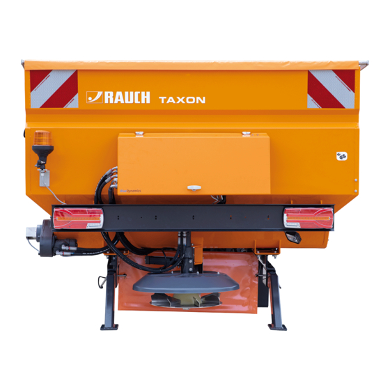
OPERATOR'S MANUAL
Please read carefully
before using the ma-
chine.
Keep for future reference.
This instruction manual/assembly in-
struction is to be considered as part of
the machine. Suppliers of new and se-
cond-hand machines are required to
document in writing that the instructi-
on manual/assembly instruction was
delivered with the machine and han-
ded over to the customer.
Original manual
b
5903060-
-en-1020
Advertisement
Table of Contents

Related Manuals for Rauch TAXON 25.1


Summary of Contents for Rauch TAXON 25.1
- Page 1 OPERATOR'S MANUAL Please read carefully before using the ma- chine. Keep for future reference. This instruction manual/assembly in- struction is to be considered as part of the machine. Suppliers of new and se- cond-hand machines are required to document in writing that the instructi- on manual/assembly instruction was delivered with the machine and han- ded over to the customer.
- Page 2 This constitutes no obligation to make such improvements or changes on machines that have already been sold. We will be pleased to answer any other questions that you might have. Yours sincerely RAUCH Landmaschinenfabrik GmbH...
-
Page 3: Table Of Contents
CONTENT Safety .......................... 5 1.1 Symbols for safety instructions ....................5 1.2 Machine safety......................... 6 1.3 Authorised users ........................6 1.4 Usage according to specifi cation ................... 6 1.5 Dimensions and axle loads ..................... 7 1.6 Danger sources ........................7 1.7 Transportation and packing during fi rst delivery .............. - Page 4 Start-up of the spreader ..................22 4.1 Starting vehicle and taking spreader into operation ............22 4.2 Setting the spreading pattern ....................22 4.3 Operation of the manual control ..................23 4.4 Information for the hydraulic system .................. 23 Stand emptying ........................24 Maintenance, greasing and cleaning ..............
-
Page 5: Safety
Safety Symbols for safety instructions Safety instructions in this instruction are marked as follows: Warning! Indicates potentially dangerous situations. If you do not avoid these, death or serious injuries could be the consequences. Careful!/Attention! Indicates potentially dangerous situations. If you do not avoid these, light or small injuries could be the consequences. Important! Indicates application tips and other especially useful information. -
Page 6: Machine Safety
Machine safety The spreaders of the series “Tracon” are equipped with protective installations and subjected to a safety test. However, in case of careless or gross negligent behaviour dangers exist for body and life of the operator and other persons or dangers of damage to the machine or other assets. This documentation contains information, which generally must be observed! This must be read and understood before the fi rst assembly and start-up by the assembler, workshop foreman and operator. -
Page 7: Dimensions And Axle Loads
Dimensions and axle loads The vehicle dimensions as well as the axle loads of the carrier vehicles will be altered in case of assembled spreaders. This must be taken into account by the operating personnel, whereby especially the permissible axle loads in case of fi lled spreading container and brine tank must be considered. The weights and dimensions must be taken into consideration in case of devices combinations with other add-on units (e.g. - Page 8 • Driving performance, steering and braking capability are infl uenced by mounted or attached ballast weights! Therefore, pay attention to suffi cient steering and braking capability! • Before leaving the tractor and before every setting, maintenance and repair work fully lower the spreading device! Switch off the motor, take out the ignition key and wait for complete standstill of all moving parts! •...
- Page 9 1.6.3 Spreading disk and discharge chute The spreader is fi tted with a rotating spreading disk (1), largely covered with a protective installation (2, cover umbrella). Only in the area of the material feed and the fl inging out area can the spreading disk not be fully covered. •...
- Page 10 1.6.5 Tread If the spreader has a tread at the container (1) as special equipment, the following must be observed: • One person may at maximum step onto the tread! • Step on the tread only with safety shoes! • Stepping on the tread is prohibited in case of iced or snow-covered access –...
-
Page 11: Transportation And Packing During Fi Rst Delivery
1.6.9 Protective clothing for personnel Skin contact with hydraulic oil, grease, lacquer, etc. is possible during operation or maintenance of the spreader. Wear protective clothing for respective work at the spreader! Observe the respective safety regulations for the products to be touched! The owner has to take care of the protective clothing for the operating personnel. -
Page 12: Protective Installations And Safety Stickers
Protective installations and safety stickers The protective installations and safety stickers of the spreader are depicted on the following pages. In addition, you will fi nd a check list for their checking. Check the protective installations: • Before every spreading application •... -
Page 13: Depiction Of Protective Installations And Safety Stickers
Depiction of protective installations and safety stickers Stand 25.05.2011 Seite 13 Page 13 Operating instruction TAXON of 42... -
Page 14: Check List For Checking The Protective Installations
Check list for checking the protective installations Use the available list for checking: • The device safety cover (1) must be tightly screwed on the spreading container! • The sticker “Crushing danger” (2) must be placed good visible near the device safety cover! •... -
Page 15: Assembly And Disassembly Of The Spreader
Assembly and disassembly of the spreader Preparation for fi rst assembly at the carrier vehicle If the spreader is delivered by a haulage company, diverse small parts are packed protected into the spreading container. The spreading container must be completely emptied during the fi rst assembly. For this, loosen the lashing belts fi xing the spreader tight to the wood pallet. -
Page 16: Attaching To The Rear Three-Point Attaching Device
3.3.4 Drive command connection cable See separate operating instructions for the respective control panel. 3.3.5 Connection cable to the spreader See separate operating instructions for the respective control panel. Attaching to the rear three-point attaching device The spreaders of the series ”Tracon” fi t all tractors equipped with a standard three-point attachment possibility. - Page 17 3.4.1.2 Fastening of lower control arms Fasten the two lower control arms (1) of the tractor to the attaching bolts of the spreader and secure with a hinged cotter. If the tractor has quick change equipment, the two lower control arms caching balls (2) on the tractor side must be pushed onto the attaching bolts (3) and secured with a hinged cotter! After fastening the lower control arms secure the attaching bolts with hinged cotter!
-
Page 18: Safety Distance To Be Kept
3.4.1.4 Connection to the vehicle hydraulic system If the tractor has an adequate hydraulic supply for the spreader (40 litres/min. at 190 bars pressure), an own hydraulic system, like described under point 3.4.1.4, is not necessary. Instead of the articulated shaft, two hydraulic hose lines will then be connected to the spreader – one pressure line and one return line. -
Page 19: Disassembly Of The Serial Parking Legs And The Wood Transportation Pallet
Disassembly of the serial parking legs and the wood transportation pallet After attaching, lift the spreader lightly with the three-point attachment of the tractor. Safety distance: Minimum 200 mm Then pull out the delivered wood pallet from under the spreader. Never reach under the lifted spreader! The spreader is delivered ex work with a series parking system (two parking legs, 1) taking the weight of the unloaded spreader. -
Page 20: Correct Working Height
Correct working height The working height is adjusted correct, if the spreading disk is about 35 to 45 cm above ground. In this position, the spreading container should be attached absolutely straight to the tractor. Working height: Spreading disk 35 to 45 cm above ground Safety loop The spreader is in series equipped with two safety loops (1). -
Page 21: Disassembly Of The Spreader
Disassembly of the spreader The disassembly is carried out in reverse order: • Attach the parking legs on the left and right to the spreader and let the locking bolt lock in • Lower the spreader to the ground by operating the tractor hydraulic system Pay attention that no persons stand near the spreader! •... -
Page 22: Start-Up Of The Spreader
Start-up of the spreader Starting vehicle and taking spreader into operation • Check the spreader with the check list (2.2) for safety. • Start vehicle and take hydraulic system into operation. For spreaders with own hydraulic system supply, switch on power take off shaft according to the operating instruction of the tractor. Max. -
Page 23: Operation Of The Manual Control
Fig.: 1 If the material impact point on the spreading disk is to the right of the spreading disk shaft, the spreading material will be discharged to the left in driving direction. Fig.: 2 If the impact point is in front of the spreading disk shaft, the spreading material will be evenly discharged to the left and right. -
Page 24: Stand Emptying
Stand emptying To empty the container when standing, proceed as follows: • Pay attention to all warning information like the ones described in chapter 4. • Place the carrier vehicle on an even, solid ground. Ensure that the handbrake is put on. •... -
Page 25: Maintenance, Greasing And Cleaning
Maintenance, greasing and cleaning The drive of the carrier vehicle must be switched off for all maintenance, greasing and cleaning work! Observe safety information or take suitable measures for accident prevention! The spreader is largely maintenance-free during the winter service use. Still, regular checks and a certain basic care are the basic precondition for maintenance-of value! Greasing spreading disk shaft The spreading disk shaft (1) has been designed in such a way that it must... -
Page 26: Cleaning Of The Spreader
Cleaning of the spreader It makes sense cleaning the spreader after every usage with clean water (without pressure) from salt residues and brine splashes. You should refrain from use of chemical cleaning agents! • Do not use high-pressure cleaners for cleaning the spreader, as the lacquer or cable penetrations of the electronic components can be damaged! •... - Page 27 Type of soiling Cleaning Special agents Information Wiping off with soft dry cloth, rinsing Dust, soot To avoid water marks with water Possibly repeated drying) (1) Finger prints, Washing off with household cleaner Ambra, Lux Flüssig, Vif, Hard water may leave lime Slight grease and oil marks (without scouring additive).
-
Page 28: Electrical System
• Attention must be paid when working on the stainless steel spreader that no steel tools or steel screw connections are used (Use stainless steel screws!). • Also, no steel parts must be welded or screwed on. • In addition, there must be no direct contact with steel parts, e.g. loading bridge. •... -
Page 29: Flange Bearing
Flange bearing The auger is supported by a fl ange gearing (1) on the side opposite from the chain gear unit (2). This fl ange bearing is fi tted with a grease nipple. Greasing interval: Weekly Grease: Acid-free grease 5.11 Hydraulicplan Hydraulic block „SRCA“... - Page 30 5.12 The annual UVV - test (to BGV-D29) Machines and systems lose their functionality over time (e. g. due to corrosion, wear and tear). Loss of function does not only lead to quality defects in use, but also the safety technical facilities can be impaired. To counteract this eff ect, the Bucher Municipal Wernberg GmbH off ers maintenance intervals, and occupational health and safety requires compliance with the inspection intervals in accordance with the accident prevention regulations (UVV inspections).
-
Page 31: Possible Fault Indications - Troubleshooting
Possible fault indications – Troubleshooting Should faults occur on the spreader, this could have, of course, various causes. The basic condition is always that suffi cient voltage and suffi cient hydraulic power is available. • Remove the fault after having found the cause only, when the drive is switched off . •... - Page 32 Auger (Signal in the display:”Check auger) Fault/Signal: Possible cause: Remedy: No hydraulic pressure Check hydraulic system Magnet of hydraulic valve without power Check electric power Hydraulic valve defect Replace valve Overpressure cartridge has triggered – Check pressure Augers do not run Blocked auger Remove foreign body Blocked discharge chute...
-
Page 33: Graphic Display Of Components
Graphic display of components 6.2.1 Measuring probe The measuring probe is located on the back of the spreader to the left of the spreading part. In the double chamber version (special equipment) 2 measuring probes are installed (grit and salt area). If the spreader is empty, the measuring probe reports this to the control panel in the driver‘s cab. - Page 34 6.2.3 Electonic spreading control (Infrared - ESK) Sensor Infrared - ESK The sensor should be cleaned with a damp cloth before each use. Setting the measuring fi eld of the infrared spreading control: The setting must be made with the hydraulics switched off ! Type A: Switch on the EcoSat or EcoTron control.
- Page 35 6.2.4 Auger monitoring For spreaders completely position-dependent (Control panel EcoSat), the speed of the hydraulic motor shaft at the chain gear unit is monitored with a auger monitoring and reported to the control panel in the driver’s cabin. The control panel balances these actual data with the nominal data and corrects these, to guarantee a very accurate spreading quantity.
-
Page 36: Technical Data - Series Taxon
Technical Data - Series TAXON Spreading width: 2 - 8 metres (in 0.5 metres steps) Spreading quantity dry material: Grit: 10,0 g/m² - 250 g/m² Salt: 5,0 g/m² - 40 g/m² Drive: Fully hydraulic drive of the auger and the spreading disk via the vehicle hydraulic system Oil consumption: 60 l/min must not be exceeded! - Page 37 Technical Data TAXON 25.1 Dry material volume: m³ Wet salt volume (FS): Container depth: Total width: 2.000 Gravity centre without FS: * Gravity centre with FS: * Side wall height: 1.130 Empty weight without FS: Empty weight with FS: Empty weight double chamber: Empty weight double chamber wet salt: Spreading quantity salt: g/m²...
-
Page 38: Important Information
Important information This machine complies with the safety requirements of the European machine guideline. The manufacturer refuses any responsibility, if the spreader is not used according to the instructions given in the operating instruction! The user must observe exactly the general safety regulations as well as the regulations of the Health and Safety Executive! Our recommendations and safety instructions make no claim to completeness! Stand 25.05.2011... - Page 39 Description of the machine (replaceable facility): Single chamber spreader or double chamber spreader (For design DK!) for winter service Type: These are the spreaders of the series TAXON 25.1. Applied harmonised standards: EN 12100, Safety of machines, basic terms, general design guidelines...
- Page 40 Stand 25.05.2011 Seite 40 Page 40 Operating instruction TAXON of 42...
- Page 41 Warranty claims are rendered void if RAUCH original spare parts were not used. Therefore, the directions in the operating manual must be observed. In all cases of doubt contact our sales representatives or the factory directly.
Need help?
Do you have a question about the TAXON 25.1 and is the answer not in the manual?
Questions and answers