Table of Contents
Advertisement
Quick Links
INSTRUCTION MANUAL
Please read carefully
before using the ma-
chine.
Keep for future reference.
This instruction manual/assembly in-
struction is to be considered as part of
the machine. Suppliers of new and sec-
ond-hand machines are required to
document in writing that the instruc-
tion manual/assembly instruction was
delivered with the machine and hand-
ed over to the customer.
Original instructions
a
5902722-
-en-0818
Advertisement
Table of Contents

Subscribe to Our Youtube Channel
Related Manuals for Rauch RFZ 7


Summary of Contents for Rauch RFZ 7
- Page 1 INSTRUCTION MANUAL Please read carefully before using the ma- chine. Keep for future reference. This instruction manual/assembly in- struction is to be considered as part of the machine. Suppliers of new and sec- ond-hand machines are required to document in writing that the instruc- tion manual/assembly instruction was delivered with the machine and hand- ed over to the customer.
-
Page 2: Technical Improvements
Preface Dear customer, By purchasing this row fertiliser RFZ 7, you have shown confidence in our product. Thank you! We want to justify this confidence. You have purchased a powerful and reliable machine. However, in case unexpected problems arise: Our customer service team are always there for you. -
Page 3: Table Of Contents
Inhaltsverzeichnis Preface Technical improvements Intended use User instructions About this operator’s manual ......... . . 3 Structure of the operator’s manual . - Page 4 Inhaltsverzeichnis Mounting Accepting the special equipment ........15 Preparation of the components .
- Page 5 Inhaltsverzeichnis Faults and possible causes Maintenance and service Safety............49 Wear parts and screw connections .
- Page 6 Inhaltsverzeichnis...
-
Page 7: Intended Use
Intended use Intended use The row fertiliser RFZ 7 may only be used in accordance with the information giv- en in this operator’s manual. The row fertiliser RFZ 7 has been constructed in accordance with its intended use. The row fertiliser may only be used for the application of dry, granular and crys- talline fertilisers and slug pellets. - Page 8 Intended use...
-
Page 9: User Instructions
User instructions User instructions About this operator’s manual This operator’s manual is an integral part of the machine. The operator’s manual contains important information for a safe, appropriate and economic use and maintenance of the machine. Adherence to this opera- tor’s manual helps to avoid risks, to reduce repair costs and downtime, and to increase the machine's reliability and service life. -
Page 10: Notes On Text Descriptions
User instructions Notes on text descriptions 2.3.1 Instructions and procedures Steps that the operator must carry out are shown as a numbered list. 1. Instruction for action step 1 2. Instruction for action step 2 Instructions involving only one step are not numbered. The same applies for ac- tion steps that do not have a specific sequence. -
Page 11: Safety
Safety Safety General Information The chapter Safety contains basic warning notes as well as working and traffic safety instructions for the usage of the installed machine. The adherence to the instructions in this chapter is a prerequisite for the safe han- dling and trouble-free operation of the machine. - Page 12 Safety Warning severity level The degree of danger is indicated by the signal word. The levels are classified as follows: n DANGER Type and source of danger This warning warns of a danger posing an immediate threat to the health and life of persons. Ignoring these warnings will result in very serious or even fatal injury.
-
Page 13: General Information On The Safety Of The Machine
General information on the safety of the machine NOTICE You may use the RFZ 7 row fertiliser ONLY with the MDS fertiliser spreader. The row fertiliser is available as special equipment of a machine. The chapter Safety in the operator’s manual of your machine is to be re- ... -
Page 14: Hazard Zone
Safety 3.4.4 Hazard zone Ejected spreading material may lead to severe injury (e. g. to eyes). When persons are present between the tractor and the machine, there is a great hazard caused by the tractor rolling away or by machine movements which may have fatal consequences. -
Page 15: Maintenance And Service
Safety Never climb onto the machine or the tractor when it is situated beneath high- voltage electrical power lines. Maintenance and service Maintenance and service involve additional hazards that do not occur during op- eration of the machine. Any maintenance and service work is to be conducted with increased alert- ... -
Page 16: Using The Machine For Transport
Safety 3.6.2 Using the machine for transport The handling, tilting, steering, and braking performance of the tractor is affected by the attached machine. For example, the high load will reduce the weight on the tractor's front axle and affect its steering. Be aware of the changed driving behaviour. -
Page 17: Technical Data
Technical data Technical data Manufacturer RAUCH Landmaschinenfabrik GmbH Landstraße 14 D-76547 Sinzheim Phone: +49 (0) 7221 / 985-0 Fax: +49 (0) 7221 / 985-200 Service Centre, Technical Customer Service RAUCH Landmaschinenfabrik GmbH Postfach 1162 D-76545 Sinzheim Phone: +49 (0) 7221 / 985-250... -
Page 18: Description Of The Special Equipment
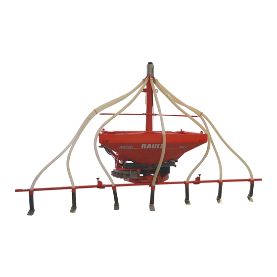
[4] Hose [9] Adjustable struts [5] Support frame side part [10] Pipe with auger Overview of supported MDS fertiliser spreaders You can attach the special equipment RFZ 7 to the following fertiliser spreaders with/without extension. Basic machine MDS 11.1 ... -
Page 19: Technical Data Of Basic Equipment
478.5 cm (unfolded) Overall width of central and side parts 207.5 cm (folded) Working width approx. 500 cm Mass flow max. 63.8 kg/min 1. Max. mass flow depending on fertiliser type Weights and loads: Data RFZ 7 Empty weight 107 kg... - Page 20 Technical data...
-
Page 21: Mounting
Mounting Mounting Accepting the special equipment When accepting the special equipment, please check the completeness of the scope of delivery. Check for any transport damage or missing construction parts. Have any trans- port damage confirmed by the forwarding agent. In case of doubt, please contact your dealer or the factory directly. The standard equipment includes: 1 Operator’s manual ... - Page 22 Mounting 2 locking mechanisms 4 adjustable struts Hoses (7 pieces) with clamps ...
- Page 23 Mounting Outlet pipe with baffle plate (7 pieces) 2 hose brackets 2 protective grid halves ...
-
Page 24: Preparation Of The Components
Mounting Preparation of the components 2-man assembly preferred. Observe the order of assembly steps listed in the next sections. 5.2.1 Sorting the hoses Figure 5.1: Hoses of different lengths [1] 1 hose, length 2450 mm [2] 2 hoses, length 2600 mm [3] 2 hoses, length 2950 mm [4] 2 hoses, length 3350 mm Remove the hoses from the packaging and sort them in such a way that the... -
Page 25: Preparing The Hopper
Mounting 5.2.2 Preparing the hopper Requirements Set the MDS fertiliser spreader higher. This makes it easier to assemble the lower part of the special equipment. For this, fit the MDS fertiliser spreader to the tractor or place the MDS fertiliser spreader on pallets Minimum distance (free space) to the ground: 1 metre ... -
Page 26: Removing The Agitator
Mounting 5.2.3 Removing the agitator 1. Turn the agitator head [1] clockwise. The agitator head is loose. 2. Remove the agitator head [1] and put this somewhere safe. Figure 5.4: Remove the agitator Assembling the special equipment 5.3.1 Positioning the special equipment 1. -
Page 27: Fastening The Hoses
Mounting 5.3.2 Fastening the hoses First, install the longest hoses onto the outermost profiles on the left and right. Carry on with hose pairs until you reach the centre. Install the shortest hose in the centre. 1. Attach the hoses [1] with the hose clamps [2] to the spe- cial equipment. -
Page 28: Fastening The Hose Bracket
Mounting 5.3.3 Fastening the hose bracket 1. Measure the distance from the upper edge of the slide to the hose bracket. Approx. 950 mm for all models 2. Mark the measured position with a pen. 1. Place the hose bracket [1] on the position marked accord- ingly. -
Page 29: Placing The Components In The Hopper
Mounting 5.3.4 Placing the components in the hopper 1. Attach the lifting gear [2] to the intended attachment points [1]. Figure 5.10: Lifting gear at attachment points NOTICE Attach the chain between the two hoses above. This prevents the pressure of the chain on the hoses when the components are being assembled. -
Page 30: Attaching Protective Grid
Mounting 3. Align the base correctly. The metering slides must remain visible. Figure 5.12: Align base NOTICE Under no circumstances cover the metering slides of the hopper. Otherwise, you cannot carry out the later emptying of residual material and cleaning work. 5.3.5 Attaching protective grid 1. -
Page 31: Mounting The Adjustable Struts
Mounting 5.3.6 Mounting the adjustable struts 1. Measure the position of the half shells of the struts from the hopper base of the fertiliser spreader. MDS 11.1: approx. 650 mm MDS 12.1: approx. 770 mm MDS 17.1: approx. 657 mm ... - Page 32 Mounting n CAUTION Hazard due to unstable device! The stability of the special equipment in the hopper is only guar- anteed by the struts. If the screws are not correctly tightened, there is a danger that the special equipment will tip. This can lead to physical injuries or property damage.
-
Page 33: Attaching The Support Frame To The Fertiliser Spreader
Mounting Attaching the support frame to the fertiliser spreader 5.4.1 Attaching the central part of the support frame Requirement The fertiliser spreader is placed on even ground. Horizontal position of the fertiliser spreader 1. Prepare the central part of the support frame [1], the plug [2] and the clip connec- tor [3]. -
Page 34: Installing The Side Parts
Mounting 5.4.2 Installing the side parts 1. Apply sufficient lubricant to the holes [1] of the central part. 2. Place one adjusting washer [2] on each from above. Figure 5.19: Place adjusting washer 3. Prepare both side parts of the support frame. The side with the holes should face the central part. -
Page 35: Assembling Outlet Pipes
Mounting 1. Lubricate the bolts and com- pression springs of the lock mechanisms. 2. Lubricate all latch positions of the bolts and the running surfaces which the side parts move along. Figure 5.21: Lubricate the lock mechanism 5.4.3 Assembling outlet pipes 1. - Page 36 Mounting 2. Assemble the remaining out- let pipes [2]. For this, remove the U-bolt [1] from the outlet pipe and attach it to the marked posi- tion. Figure 5.24: Assemble outlet pipes Inserting hoses into the outlet pipes 3. Insert hoses into the outlet pipes: Insert the central and shortest hose into the centre outlet pipe.
-
Page 37: Adjusting Special Equipment For A Few Rows
Mounting 5.4.4 Adjusting special equipment for a few rows If you wish to spread in fewer than 7 rows, you need to adjust the special equip- ment. 1. Detach unnecessary outlet pipes and store them somewhere safe. 2. Readjust the outlet pipes on the side and central part in accordance with the new row distance. - Page 38 Mounting...
-
Page 39: Machine Settings
Machine settings Machine settings n DANGER Danger of injury from running engine Working on the machine while the engine is running may result in serious injuries caused by mechanical components and escaping fertiliser. Switch the tractor motor off. Remove the ignition key. ... -
Page 40: Setting The Application Rate
Machine settings Setting the application rate You set the application rate via the stopper lever at the adjusting segment of the metering slide actuator. 1. The scale value [2] for the desired application rate can be found in the fertil- iser chart. -
Page 41: Using The Fertiliser Chart
Machine settings Using the fertiliser chart 6.2.1 Information on the fertiliser chart The values in the fertiliser chart have been determined by the test system. The used fertiliser materials have been purchased from the fertiliser manufactur- ers or from dealers. Experience shows that due to storage, transport and other reasons, your fertiliser –... -
Page 42: Settings As Per Fertiliser Chart
Machine settings 6.2.2 Settings as per fertiliser chart The operator determines the optimal spreading from the fertiliser chart accord- ing to the type of fertiliser, working width, rotation speed of the PTO shaft and driving speed. NOTICE The given working widths and spreading quantities are calculated for the aver- age row distance of 75 cm. - Page 43 Machine settings Fertiliser type: Calcium-ammonium nitrate Spreading width: 5.25 m PTO speed: n = 540 min Spreading quantity (kg/ha) Scale value kg/min 10.8 14.4 18.0 21.6 24.8 28.0 31.2 km/h 1. Calibration test volume per minute Spreading quantity (kg/ha) Scale value kg/min 34.5 37.9 41.2 43.8 46.4 49.0 51.6 54.2 56.8...
- Page 44 Machine settings Fertiliser type: Urea Spreading width: 5.25 m PTO speed: n = 300 min Spreading quantity (kg/ha) Scale value kg/min 13.1 16.3 19.6 22.8 25.7 28.6 31.5 km/h 1. Calibration test volume per minute Spreading quantity (kg/ha) Scale value kg/min 33.6 35.8 37.9 38.8 39.6 40.4 41.4 42.3 43.1...
- Page 45 Machine settings Fertiliser type: Urea Spreading width: 5.25 m PTO speed: n = 540 min Spreading quantity (kg/ha) Scale value kg/min 11.4 15.4 20.0 24.6 29.2 32.7 36.1 39.6 km/h 1. Calibration test volume per minute Spreading quantity (kg/ha) Scale value kg/min 43.5 47.3 51.2 53.3 55.4 57.5 59.6 61.7 63.8...
-
Page 46: Setting The Working Width
Machine settings Setting the working width To fertilise rows of plants of differing widths, set the outlet pipes on the central and side parts of the support frame according to your requirements. In addition, you can detach the baffle plate so that the fertiliser falls onto the soil directly under the outlet pipes. -
Page 47: Spreading Without Baffle Plate Onto The Rows Of Plants
Machine settings 6.3.2 Spreading without baffle plate onto the rows of plants Figure 6.3: Spreading without baffle plate Track 1. Remove the baffle plate from the outlet pipes. 2. Loosen the outlet pipe ring nuts. 3. Swivel the outlet pipes to the left and right and tighten the ring nuts again. ... - Page 48 Machine settings...
-
Page 49: Spreading Operation
Spreading operation Spreading operation Instructions regarding the spreading operation The intended use of the machine includes compliance with the operating, main- tenance, and service conditions in accordance with the manufacturer specifica- tions. Spreading operation therefore always includes preparation and cleaning/maintenance. n DANGER Danger of injury when spreading Contact with rotating machine components may cause injury. -
Page 50: Setting The Special Equipment Into Working Position
Spreading operation 4. Pull the locking mechanism of the support frame side part upwards. 5. Fold the support frame side part inwards. Figure 7.2: Fold closed the support frame side part. 6. Insert the lock mechanism into the hole and release. ... -
Page 51: Starting The Spreading Operation
Spreading operation 7.1.3 Starting the spreading operation Requirement: You have detached the spreading discs. The row fertiliser is in working position. The hoses have been inserted deeply into the outlet pipes. 1. Attach the fertiliser spreader with row fertiliser to the tractor. Follow the instructions and safety instructions in the operator's manual of the MDS fertiliser spreader. -
Page 52: Discharging Residual Material
Spreading operation Discharging residual material We recommend emptying the machine immediately after every use to maintain its value and to ensure a fault-free spreading operation. 1. Deactivate the drive and switch off the tractor motor. 2. For collecting the spreading material, place a foil under the machine or posi- tion a sufficiently sized hopper beneath the outlet. -
Page 53: Faults And Possible Causes
Faults and possible causes Faults and possible causes n WARNING Risk of injury when rectifying faults inappropriately Delayed or incorrect repairs by unqualified personnel may result in severe personal injury as well as in damages to the machine and the environment. ... - Page 54 Faults and possible causes Fault Possible cause Measure Metering slide does not open. Check and, if necessary, improve the smooth move- ment of the metering slide actuator (lever and joints). Remove dirt from the slide which can cause jams. The screw conveyor is not Check free path and free ...
-
Page 55: Maintenance And Service
Maintenance and service Maintenance and service Safety HINWEIS Please also refer to the warning notes in chapter 3: Safety, page 5. Take parti- cular note of the instructions in section 3.5: Maintenance and service, page Maintenance and service involve additional hazards that do not occur during ope- ration of the machine. -
Page 56: Checking Screw Connections
Maintenance and service 9.2.2 Checking screw connections Bolted joints have been tightened to the specified torque and locked at the facto- ry. Vibrations and shocks, in particular during the initial operating hours, can loo- sen bolted joints. With new machines, all screw connections are to be checked for their tight ... -
Page 57: Removing The Screw Conveyor
Maintenance and service Removing the screw conveyor Requirement: Open the fertiliser spreader metering slide. Empty the residual quantity of the hopper. This avoids fertiliser running out onto the base. 1. Attach and secure lifting gear to both stopper points of the screw tube. - Page 58 Maintenance and service 1. Remove the upper pipe plug cap [1] from the screw tube [2]. Figure 9.4: Remove the pipe plug cap 2. Remove the linchpin [1]. Figure 9.5: Remove the linchpin 3. Unscrew the three clip connectors [1] which secure the base to the screw tube.
-
Page 59: Removing The Slide
Maintenance and service 5. Carefully pull out the screw conveyor [1] from underneath. Figure 9.7:Pull out the screw conveyor Removing the slide 1. Loosen connection of the push-pull cable to the slide. 2. Pull the slide out from the top and remove from the screw tube. -
Page 60: Lubrication
Maintenance and service Lubrication 9.6.1 Lubrication plan Lubrication points Lubricant Note Lock mechanisms bet- Grease Lubricate the bolts and the running surfaces of the ween support frames elements. Lubricate regularly, however at the latest and side parts when the elements lose their sliding capacity. Page 28 Inner side of slide Grease... - Page 61 Maintenance and service 2. Lubricate the screw socket [1]. Figure 9.10:Socket of the screw conveyor 3. Lubricate the joint between the central and side parts Figure 9.11:Support frame joint 4. Lubricate the inner side of the slide in the upper area. Figure 9.12:Inner side of slide...
- Page 62 Maintenance and service 5. Lubricate the inner side of the slide sprockets. Figure 9.13:Slide sprockets...
-
Page 63: Disposal
Disposal Disposal 10.1 Safety n WARNING Environmental pollution due to unsuitable disposal of hy- draulic and gear oil The hydraulic and gearbox oils are not entirely biodegradable. Therefore, oil must be prevented from entering the environment in an uncontrolled manner. ... -
Page 64: Disposal
Disposal 10.2 Disposal The following points are applicable without any restriction. Stipulate suitable pre- cautionary measures based on the national legislation and implement them. 1. All components, auxiliary and operating materials from the machine must be removed by specialist staff. Hereby, these components and substances must be cleanly separated into categories. -
Page 65: Index
Index Index Adjustable struts Machine 16, 25 Description 12 Application rate Disposal 57 Assembly overview Faults 47 Auger intended use 1 Misuse 1 parking 7 Baffle plate 17, 29 Settings 33–41 Spreading operation 43–46 Transport position 43–44 Central part 15, 43 Transportation 10 Maintenance 49–55... - Page 66 Index Screw tube Service Technical data 49–55 11–13 Dimensions 13 Settings 33–41 Weights and loads 13 Application rate 34 Transportation 10, 43–44 Fertiliser chart 36 Working width 40 Side part 15, 28, 44 Spreading operation 43–46 intended ~ 1 Start-up User instructions Checks before ~ 7 Strut...
-
Page 67: Terms/Conditions Of Warranty
Warranty claims are rendered void if RAUCH original spare parts were not used. Therefore, the directions in the operating manual must be observed. In all cases of doubt contact our sales representatives or the factory directly.
Need help?
Do you have a question about the RFZ 7 and is the answer not in the manual?
Questions and answers