Table of Contents
Advertisement
Quick Links
Advertisement
Table of Contents

Summary of Contents for Cablematic Tenmars
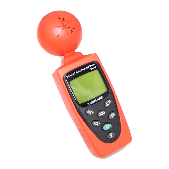
- Page 1 RF three-Axis Field Strength Meter Strength Meter User’s Manual...
-
Page 2: Table Of Contents
Contents Axis RF Meter Quick Start Guide ..........1 Introduction ................. 2 Simple a method of operation ..........2 Fundamentals ..............3 Electric field strength (E): ..........3 Magnetic field strength (H): ......... 3 Power density (S): ............4 The characteristic of electromagnetic fields(S): ..4 Application ................ - Page 3 15 Safety Information ............. 27 16 Safety Information ............. 28 17 Battery replacement ............29 18 Safety Precaution .............. 29 19 Product Disposal ............... 29...
-
Page 4: Axis Rf Meter Quick Start Guide
Axis RF Meter Quick Start Guide This meter has many capabilities, including memory, alarm, date/time, average etc. which will require some study of the manual to use properly. However, you can quickly and easily begin making measurements right out of the box. Just follow these simple steps: Insert 9V battery. -
Page 5: Introduction
Introduction This meter is designed for measuring and monitoring Radio–Frequency electromagnetic field strength. The meter is calibrated precisely over the frequency range of 50Mz~3.5 GHZ. Simple a method of operation Press “ ” button to power on. To change measuring unit (mV/m), push “ ”... -
Page 6: Fundamentals
Fundamentals Electromagnetic pollution: This meter is used to indicate electromagnetic pollution generated artificially. Wherever there is a voltage or a current, electric (E) and magnetic (H) fields arise. All types of radio broadcasting and TV transmitters produce electromagnetic fields, and they also arise in industry, business and the home, where they affect us even if our sense organs perceive nothing. -
Page 7: Power Density (S)
3.3 Power density (S): Power per unit area normal (perpendicular) to the direction of propagation, usually expressed in units of Watts per square meter (W/m ) or, for convenience, units such as mill Watts per square centimeter (mW/cm 3.4 The characteristic of electromagnetic fields(S): Electromagnetic fields propagate as waves and travel at the speed of light (C). -
Page 8: Application
Application Quite often routine, maintenance and service work has to be done in areas where active electromagnetic fields are present, e.g. in broadcasting stations, etc. Additionally, other employees may be exposed to electromagnetic radiation. In such cases, it is essential that personnel be not exposed to dangerous levels of electromagnetic radiation, such as: ... -
Page 9: Electromagnetic Safety Reference Standard
electromagnetic safety reference standard 1W/m² =0.1mW/Cm² =100uW/Cm² Features The meter is a broadband device for monitoring high- frequency radiation in the range from 50MHz to 3.5GHz The non-directional electric field antenna and high sensitivity also allow measurements of electric field strength in TEM cells and absorber rooms. - Page 10 The meter can be set to display the instantaneous value, the maximum value measured or the average value. Non-directional (isotropic) measurement with three-axis measurement sensor. High dynamic range due to three- channel digital results processing. Configurable alarm threshold and memory function.
-
Page 11: Identifying Parts
Identifying Parts RF three-Axle Sensor. Liquid-crystal LCD. MAX / AVG / R Button. Record / Time / L Button. Power Button. UNIT / ENTER switch Button. Hold / ALARM on/off / Up Button. Backlight/Set. X.Y.Z / MEM / Down Button. Holster. -
Page 12: Lcd Description
LCD description 1. Primary Display 13. E symbol 2. Hold symbol 14. Auto power off 3. Analogue bar graph symbol 4. MAX symbol 15. Time unit (month:day) 5. AVG symbol (hour: minute) 6. Low battery symbol (second) 7. x1x10x100 unit 16. -
Page 13: Specifications
Specifications 9.1 General specifications Display type : Liquid-crystal (LCD), 4-1/2 digits maximum reading 19999. Measurement method : Digital, triaxial measurement. Directional characteristic : Isotropic (triaxial). Measurement range selection: one continuous range. Display resolution : 0.1mV/m, 0.1µA/m, 0.01µW/m , 0.001µW/cm ... -
Page 14: Electrical Specifications
Battery life : Approximate 15 hours. Auto power off : Default time 15 minutes. Adjustable threshold 0~99 minutes. Operating temperature range : 0°C to + 50°C. Operating humidity range : 25% to 75% RH. Storage temperatures range : -10°C to +60°C. ... -
Page 15: Units Of Measurement
Specified measurement range: CW signal (f >50MHz) : 38mV/m to 11.00 V/m, 53.0uA/m to 29.28mA/m , 0.1uW/m to 323.3W/m², 0.001uW/cm ~32.33 uW/cm Dynamic range : Typically 75dB. Absolute error at 1V/m and 2.45GHz : ±1.0 dB. ... -
Page 16: Result Modes
field strength units (µA/m or mA/m) and power density units (µW/m , mW/m or µW/cm ) using the standard far-field formulae for electromagnetic radiation. 9.4 Result modes The bar graph display always shows the instantaneous measured dynamic range value. The digital display shows the result according to one of three modes, which can be selected. -
Page 17: Measurement Procedures And Preparation
10 Measurement Procedures and Preparation Battery loading : Remove the battery cover on the back and put a 9V battery inside. Battery replacement: When the low battery symbol of ” ” appears on the LCD display, the battery should be replaced with a new one. 10.1 POWER button:... -
Page 18: Units Button
Press the “ ” button once again to deactivate it. 10.3 Units button : Change units with the “UNITS” key as follows. Electric field strength (V/m) Computed magnetic field strength (mA/m). Computed power density (mW/m Computed power density (μW/cm Press “ ”... -
Page 19: Manual Data Memory Storing
Press and hold “ ”key for 3 seconds to disable this function. The maximum averaging storage is up to 99 minutes and 99 seconds. After this period of time, updating will stop automatically and the LCD displays 10.5 Manual data memory storing ”button, the meter will save the current Push“... -
Page 20: Backlight Display And Reading In The Dark
10.6 Backlight Display and Reading in The Dark. Press “ ” key backlight light on. Again Press “ ” button to power off. Backlight light turns off automatically after 30 seconds. 10.7 XYZ: Press ” ” this key to change sensor axis selector : ”All axis”... -
Page 21: Viewing Data Records
sounds, the display shows 10.9 Viewing Data Records Press hold “ ” button and press “ ” button to view the saved data records Use “ ” or “ ” button to see the next or previous records Press “ ”... -
Page 22: Setup Mode
11 Setup Mode While the meter is on, press hold “ ” button and “ ” button to enter the setup mode. Press “ ” button to scroll through the setup function. Push “ ” button to save setup data. Note 1 : you can set up 6 different functions in setup mode Default Clock Setup... -
Page 23: Setting The Alarm Limit Value (Alarm)-2
Use “ ” or “ ” to select the digit you want to adjust. Press “ ” button to save the setting. Date/Time default format : 2009/12/21 12:12. Year format : 2000~2099 display as 00 ~ 99. 11.2 Setting the alarm limit value (ALARM)-2 The alarm limit value determines the level at which the alarm wil sound. -
Page 24: Del Data Logger Memorysetup-3
Mode. Press “ ” button 1 more time to enter the alarm setting mode, the readout value is flashing and ”V/m” unit is displayed. Press “ ” key to move decimal. Press “ ” key to select the desired digit. Press “... -
Page 25: Analog Bar Graph Setup-4
data logger memory mode (3.SET). will show on the display. To exit without clearing memory, press “ ” key To clear the memory, press “ ” then press “ ” 11.4 Analog bar graph setup-4 While the meter in ON, press hold “ ”... -
Page 26: Auto Power Off Time Function Setup-5
11.5 Auto Power Off Time function setup-5 While the meter is on, press and hold “ ” button and press “ ”,button to enter the auto power off Setup Mode. Press “ ” button 4 more times. Press “ “ and “ ”... - Page 27 appropriate for most situations. Use “ ” or “ ” to select the desired digit. Press “ “ and “ ” button to change the digit Press “ ” key to store the new setting value and exit. Calibration factor (CAL) The calibration factor CAL serves to calibrate the display for a specific frequency when the frequency of a single signal is known.
-
Page 28: Making Measurements
12 Making measurements Important : The following effect will be noted with all field strength meters: If the sensor is moved quickly, excessive field strength values could be displayed. This effect is caused by electrostatic charges. Recommendation : Hold the meter steady during the measurement. 13 Short-term measurements Application : Use either the “instantaneous”... -
Page 29: Long-Term Exposure Measurements
sources, those components connected to a source may also act as radiators. For example , the cables used in diathermy equipment may also radiate electromagnetic energy. Note that metallic objects within the field may locally concentrate or amplify the field from a distant source. 14 Long-term exposure measurements Location Place the meter between yourself and the... -
Page 30: Safety Information
15 Safety Information CAUTION Before making a measurement, check if the ” is shown on the low battery symbol” display as soon as the meter is switched on. Change the battery if the symbol is displayed. In the case of prolonged storage, it is preferable to remove the battery from the meter. -
Page 31: Safety Information
16 Safety Information DANGER In some cases, work in the vicinity of powerful radiation sources can be a risk to your life. Be aware that persons with electronic implants (e.g. cardiac pacemakers) are subject to particular dangers in some cases. Observe the local safety regulations of the facility operation. -
Page 32: Battery Replacement
17 Battery replacement WARNING If the symbol “ ” appears on the LCD, please replace the battery immediately Turn off the instrument. Remove the battery cover Replace the battery. Install the battery cover. Be sure to turn unit off after use to conserve battery life.