tell Adapter2 Installation And Application Manual
Hide thumbs
Also See for Adapter2:
- Quick manual for installers (32 pages) ,
- Installation and application manual (116 pages) ,
- Quick manual for installers (32 pages)
Table of Contents
Advertisement
Quick Links
Product models:
Adapter2 2G.IN4.R1
Adapter2 3G.IN4.R1
Adapter2 3GA.IN4.R1
Adapter2 4G.IN4.R1
Adapter2 4GA.IN4.R1
Adapter2
Adapter2 PRO
INSTALLATION AND APPLICATION MANUAL
for device version v5.00 and newer
Document version 5.0 04.09.2018
Adapter2 PRO 2G.IN4.R1
Adapter2 PRO 3G.IN4.R1
Adapter2 PRO 3GA.IN4.R1
Adapter2 PRO 4G.IN4.R1
Adapter2 PRO 4GA.IN4.R1
Advertisement
Table of Contents

Subscribe to Our Youtube Channel
Related Manuals for tell Adapter2


Summary of Contents for tell Adapter2
- Page 1 INSTALLATION AND APPLICATION MANUAL for device version v5.00 and newer Document version 5.0 04.09.2018 Product models: Adapter2 2G.IN4.R1 Adapter2 PRO 2G.IN4.R1 Adapter2 3G.IN4.R1 Adapter2 PRO 3G.IN4.R1 Adapter2 3GA.IN4.R1 Adapter2 PRO 3GA.IN4.R1 Adapter2 4G.IN4.R1 ...
-
Page 2: Table Of Contents
System overview ........................ 5 Event sending and acknowledging ..................5 Differences between the Adapter2 and the Adapter2 PRO models........5 Differences between the 2G, 3G, 3GA, 4G and 4GA models ..........5 Terminal wiring and putting into operation ................. 6 Input wiring ......................... - Page 3 4.2.10 Voice messages ......................49 4.2.11 Advanced settings ....................... 51 Device status menu ......................53 4.3.1 Status monitoring ......................53 4.3.2 Event monitoring ......................55 4.3.3 System event logs ....................... 57 4.3.4 System logs ........................ 58 Software settings menu ....................60 4.4.1 Settings ........................
-
Page 4: Adapter2 Operation
1 Adapter2 operation 1.1 Key functions of the Adapter2 The basic function of the Adapter2 is forwarding alarm control panel’s reports to remote monitoring station using GPRS/UMTS connection. Main functions: Sends SMS, e-mail* and Push notification* with configurable message for each event ... -
Page 5: System Overview
1.5 Differences between the Adapter2 and the Adapter2 PRO models There are differences in function between the Adapter2 and the Adapter2 PRO product models. The Adapter2 PRO includes the following extra functions: ... -
Page 6: Terminal Wiring And Putting Into Operation
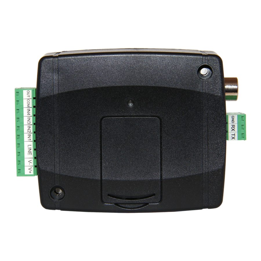
2 Terminal wiring and putting into operation 2.1 Input wiring For the inputs, the normally closed or normally open dry contact should be connected between the given input (IN1…IN4) and the negative of the power input (V-) or the COM terminal. If a normally open dry contact is used to activate the input, choose the NO (normally open) option at the given input’s settings. -
Page 7: Sim Card Socket
Insert the SIM card in the socket. The services to be activated on the SIM card installed into the Adapter2 device should be chosen according to which services of the device you wish to use. Basically, for communication with receivers and servers it requires a SIM card with mobile Internet access that may use either public or private APN. -
Page 8: Putting Into Operation
You can power up the device (12-24V DC). Make sure that the power source is sufficient for the operation of the The nominal current consumption of the Adapter2 device. however it may increase up to 500mA during Adapter2 device 120mA, communication and output control . -
Page 9: Configuring The Adapter2
The latest version of the programming software can be downloaded from the manufacturer’s website (http://www.tell.hu). The Adapter2 programming software can be used to configure all Adapter2 device models. 3.1 The user interface and configuration options of the software: The user interface language can be selected from the “Language”... -
Page 10: Configuring Directly Via Usb
Cloud: remote connection through the Internet via the cloud server operated by the manufacturer. Peer-to-peer: direct remote connection via the Internet. This option can be used if the computer running the programming software and the SIM card installed into the Adapter2 device are in the same VPN or a private APN. -
Page 11: Remote Connecting To Devices Via Cloud Service
3.2.2 Remote connecting to devices via cloud service This connection type can be used if the Adapter2 device you wish to connect remotely to, can use the cloud service. For this, the APN settings should be configured in the “General”... - Page 12 If cloud usage is enabled in the settings of the given device, the device keeps continuous connection with the cloud server. In this case skip the SMS sending process mentioned below. Cloud usage can be enabled in the “General” settings menu. If cloud usage is disabled, the device will not keep continuous connection with the cloud server, it will only connect upon request.
- Page 13 If the APN or the cloud server settings are not configured in the device, or are faulty, you can configure these using the following SMS commands: SMS command Specification APN=APN,PWD=device password# Configuring the APN Configuring the APN along APN=APN,username,password,PWD=device password# with username password belonging to it...
-
Page 14: Remote Connecting To Devices Via Peer-To-Peer Connection
APN, sending and receiving data between each other should be enabled. The SIM card installed into the Adapter2 device you wish to connect remotely to, should have a static IP address and should be part of the given private APN, respectively VPN, just like the computer from which you wish to connect to the device. -
Page 15: Remote Connecting To Devices Which Are Using The Tex-Mvp Protocol
Server password: the 20 hexadecimal-character password of the TEX server (5x4 characters separated by hyphen). Device ID: the “TEX” identifier of the Adapter2 to which you wish to connect to. The format of the “TEX” device identifier is: FFF (3 hexadecimal characters). -
Page 16: Remote Connecting To Devices Which Are Using The Tellmon Protocol
3.2.5 Remote connecting to devices which are using the TELLMon protocol This connection type can be used if the Adapter2 device you wish to connect remotely to, is connected to a TELLMon receiver and the device is configured to communicate with the TELLMon receiver using the TELLMon protocol. -
Page 17: How To Use The Adapter2 Programming Software
(e.g. differences between the PRO and non PRO device models) only when connecting the given device model, i.e. an Adapter2 device has to be connected in order to show the specific settings options of that device model. -
Page 18: Connection Type
4.1.2 Connection type In the “Connection type” menu the type of connection can be selected (USB or different options for connecting over the Internet), information can be seen about the connection process, and the admin and superadmin password can be changed. The default superadmin password is 1234. If you wish to use the admin level access as well, for this the password should be configured separately by clicking on the “Change Admin password”... -
Page 19: Device Register
Restart the device: If necessary, you can restart the connected device by clicking on this button. Restore factory default settings: By clicking on this button, you can restore the factory default settings in the device. Restoring the factory default settings will erase the actual settings, therefore please save your settings if needed. - Page 20 Function buttons available in the “Device register” menu: : save database to file : load database from file : add new device : clone entry (duplicate) : edit entry : delete entry Data stored by the device register: Device name: custom name SIM identifier (ICCID): the identifier of the SIM card inserted into the device (if the SIM card is inserted, the software reads the ID automatically from the device and inserts the data in this field when you create a new device availability entry)
-
Page 21: Device Settings Menu
4.2 Device settings menu You can configure the device settings in the submenus available in the “Devise settings” menu. Changing the device settings: In order to change the device settings, first you have to read the actual settings from the device by clicking on the “Read” button in any submenu. - Page 22 In this menu you can configure the parameters related to general operation of the device. Available options: Read the settings from the device: To read the settings from the device click on the “Read” button. This will read all settings in all menus.
- Page 23 In this section you can configure the transparent serial port settings. Configure the settings according to the requirements of the device (alarm control panel or other device) connected to the serial port of the Adapter2. Available options: baud rate, parity and stop bits.
- Page 24 GSM network after the delay configure in the “Dialing delay” section, upon picking up the receiver of the landline phone device connected to the Adapter2. When the automatic dialing function is used, the device can also be used with an alarm control panel, if an appropriate dialing delay is configured.
- Page 25 Miscellaneous settings: Incoming call from unknown phone number: in this section you can configure what the device should do when it receives a call from a phone number which is not configured in the device as a user phone number, or a call from private number (with hidden caller ID). You can configure the device to forward these calls to the simulated line output (LINE), or receive these calls and allow recording of voice messages, or reject these calls.
-
Page 26: Mobile Devices (Adapter2 Pro Only)
4.2.2 Mobile devices (Adapter2 PRO only) In this menu you can manage the access of mobile applications. The device supports access of up to 4 mobile devices, for which you can configure here the registration password requested upon assigning the mobile application to the device, and it is also possible to delete a mobile device if needed, i.e. - Page 27 Device manager: In case of assigning a mobile application to the Adapter2 device, receiving alerts from the device will become available through Push notification too. For this, when configuring events, you can select which of the up to 4 (PUSH1…PUSH4) assigned mobile devices you wish to receive a Push notification on when the given event occurs.
-
Page 28: Reporting Channels
In the “Reporting channels” menu you can configure the availabilities where notifications should be sent, such as monitoring servers or receivers, user phone numbers for calls and SMS sending, and e-mail addresses for notification by e-mail in case of using the Adapter2 PRO model. Available options: ... - Page 29 Please note that the settings have to be written in the device in order to be applied after a change is made. For this, click on the “Write” button. CID reporting to CMS over IP: You can configure up to 4 IP availabilities of CMS servers or receivers as follows. Name: CMS server or receiver name.
- Page 30 9# DTMF command using the phone’s keys. E-mail notification recipients (Adapter2 PRO only): You can configure up to 4 e-mail addresses (MAIL1 to MAIL4) to which the device will send notification upon event occurrence, according to the event settings.
-
Page 31: Notification Templates
4.2.4 Notification templates Notification templates should only be configured if reporting to CMS is needed. In this menu you can configure different templates according to which the device will send reports to CMS servers and receivers. For quick and easy setup, the device contains 2 built-in templates, named as “DEFAULT”... - Page 32 Available options: Read the settings from the device: To read the settings from the device click on the “Read” button. This will read all settings in all menus. Write the settings into the device: After changing the settings or entering new settings, in order to take effect, it is necessary to write the new settings into the device by clicking on the “Write”...
-
Page 33: Alarm System Events
4.2.5 Alarm system events The “Alarm system events” menu can be used to filter Contact-ID event codes received from the alarm control panel connected to the device. For each event filter added you can configure separately which notification template to use for reporting to monitoring station, which user to notify by call, SMS, Push notification or email and what message to send, and to control or not the output when the given event code is received from the alarm control panel, or an event code is received which matches the conditions configured in the given event filter. - Page 34 If you wish to report only specific events to CMS, add a filter that applies to all events, where choose the “New event, Restore, Repeat” option for event type and fill the event code, partition and zone number fields with " "...
- Page 35 Remote monitoring: In this section you can configure the Contact ID event code expected from the alarm control panel and can assign one of the preconfigured notification templates to the given event. -digit , consisting of Event code: in this section you can configure the 3 Contact ID event code characters 0..9,A,B,C,D,E,F, or , which...
- Page 36 Push notification (Adapter2 PRO only): in this section you can select the mobile devices to which Push notification should be sent when the given event occurs. The mobile devices should be configured in advance in the “Mobile devices”...
- Page 37 $ps: the momentarily measured value of the supply voltage Camera (Adapter2 PRO only): in this section you can select the IP camera which you wish to assign to the given event. IP cameras should be configured in advance in the “IP cameras” menu.
-
Page 38: Inputs
4.2.6 Inputs In the “Inputs” menu you can configure the default state of the 4 contact inputs, activation sensitivity, and input restore sensitivity can also be configured. Available options: Read the settings from the device: To read the settings from the device click on the “Read” button. This will read all settings in all menus. -
Page 39: Input Events
Settings: Input type: the input can be normally open (NO), or normally closed (NC). When set to NO, event is generated when the input circuit is closed, while when set to NC, opening the input circuit generates an event. The input is closed when the given input IN1…IN4 is shorted to „V-”... - Page 40 Available options: Read the settings from the device: To read the settings from the device click on the “Read” button. This will read all settings in all menus. Write the settings into the device: After changing the settings or entering new settings, in order to take effect, it is necessary to write the new settings into the device by clicking on the “Write”...
- Page 41 Remote monitoring: In this section you can configure the Contact ID event code for reporting to CMS and can select one of the preconfigured notification templates for the given event. The Contact ID event code should only be configured if reporting to CMS is used, otherwise select the notification template named “EMPTY”.
- Page 42 $ps: the momentarily measured value of the supply voltage Camera (Adapter2 PRO only): in this section you can select the IP camera which you wish to assign to the given event. IP cameras should be configured in advance in the “IP cameras” menu.
-
Page 43: Service Events
4.2.8 Service events In the “Service events” menu you can configure the custom service events of the device and notifications to be sent when a service event occurs. Service events you wish to use should be added and configured. If a service event is not added, the given event will not be generated and the device will not send notifications related to that event. - Page 44 Create a copy of an existing service event: To create a copy of the selected service event click on the “Clone” button. Please note that the new copy should have a different unique name. Edit service event settings: To edit the settings of the selected service event click on the “Edit”...
- Page 45 Remote monitoring: In this section you can configure the Contact ID event code for reporting to CMS and can select the preconfigured notification template for the given event. The Contact ID event code should only be configured if reporting to CMS is used, otherwise select the notification template named “EMPTY”.
- Page 46 $ps: the momentarily measured value of the supply voltage Camera (Adapter2 PRO only): in this section you can select the IP camera which you wish to assign to the given event. IP cameras should be configured in advance in the “IP cameras” menu.
-
Page 47: Ip Cameras (Adapter2 Pro Only)
4.2.9 IP cameras (Adapter2 PRO only) In this menu you can configure the availabilities of up to 4 IP cameras with ONVIF support, which then can be assigned to events in the event settings. If e-mail notifications are configured for events, the URL of the IP camera assigned to the given events will be sent along with the messages in the given e-mails when the events occur. - Page 48 IP address and port in the URL obtained using the ONVIF URL detector program, with the external (WAN) IP address of your router and the external port, and after this enter the modified URL in the Adapter2 programming software. Example for modification of the stream URL, if using only one camera: Original URL: rtsp://192.168.1.240:554/cam/realmonitor?channel=1&subtype=0&unicast=true&proto=Onvif...
-
Page 49: Voice Messages
4.2.10 Voice messages In this menu you can upload audio files used for notifications via voice calls, and you can also configure a custom name for each voice message. The audio files can be uploaded in mp3 or wav format. Uploaded audio files are automatically converted by the software into the format appropriate for the device. - Page 50 Edit audio file name: To edit the name of the selected audio file, click on the “Edit” button. Audio file upload: To upload an audio file to the selected voice message, click on the “Audio file upload” button. This will open a dialog box where you can browse the audio file. Voice message number: after clicking on the “Audio file upload”...
-
Page 51: Advanced Settings
4.2.11 Advanced settings In this menu you can configure advanced settings which affect communication to CMS over DTMF-based voice call and the in-call volume for calls to users (siren tone, voice messages). Special DTMF communication parameters can be configured in order to adjust signals in case of experiencing problems with reporting to CMS over DTMF-based voice call. - Page 52 3G network usage is supported by the 3G(A).IN4.R1 and the 4G(A).IN4.R1 model of the Adapter2 only! LTE network usage is supported by the 4G(A).IN4.R1 model only! Use automatic selection upon network errors: if this option is enabled, the device will select an available network when service error occurs, even if the use of a specific network is selected in the settings (2G, 3G, or LTE).
-
Page 53: Device Status Menu
4.3 Device status menu 4.3.1 Status monitoring The “Status monitoring” menu provides information on actual system status. Please note that for faster communication, in case of remote connection some of the options are not available. Status information loads and refreshes automatically only when connected through USB. Available status information: Device: ... - Page 54 Network: GSM operator: the name of the GSM operator used actually. Data connection type: type of actual data connection. GSM signal: actual GSM signal level (None/Very low, Weak, Medium, Good, Excellent). IP address: the actual IP address of the device. ...
-
Page 55: Event Monitoring
4.3.2 Event monitoring In this menu the device’s event log can be viewed and also enables you to monitor events and reporting progress online. The device stores last 100 events in its event log. Available options: Start monitoring: By clicking on this button the program will download the stored and will display new events as well. - Page 56 When connected to the device remotely, the event log can be downloaded only, online monitoring is not available. Elements of the event log: Date/time: event date/time. Name: event name, according to the event names configured at alarm system events, input events and service events.
-
Page 57: System Event Logs
4.3.3 System event logs Events related to device operation are shown in the system event logs. To download the system event logs from the device, open the “Read” drop-down menu, select how many of the latest events to be downloaded (10, 20 or all), then click on the “Read” button. -
Page 58: System Logs
4.3.4 System logs This section shows information about the internal processes and communication of the device. These details help troubleshooting if a malfunction occurs. This option is only available when connected via USB! Based on their nature, the information are splitted into channels. You can monitor one or multiple channels simultaneously. - Page 59 Start logging to file: To start logging to file click on the “Start logging” button. Logging in the background: To start logging to in the background click on the “Logging in the background” button. During the process the other functions of the system log cannot be used. ...
-
Page 60: Software Settings Menu
4.4 Software settings menu 4.4.1 Settings In the “Settings” menu you can change the user interface skin and language. Available options: Restore default layout: To restore the user interface default layout click on the “Restore default layout” button. User interface: Skin: the user interface skin can be changed using the dropdown-menu. -
Page 61: About
4.4.2 About The “About” menu shows the availabilities of the manufacturer, the version of the programming software and the path of the data folder where the software stores the logs. By double-clicking on the path, the data folder will be opened in the file manager. -
Page 62: Managing Voice Messages Via Phone Call
5 Managing voice messages via phone call For notifications by call it is possible to record up to 15 voice messages of 10 seconds each. For recording, listening to, or deleting voice messages, the number of the SIM card installed into the device should be called from a user phone number (1 to 4) configured in the device, then the desired operation can be started using the DTMF commands listed in the table below. -
Page 63: Transparent Serial Port
Adapter2 device and the Adapter2 Virtual Client software. For this, the serial port of the Adapter2 should be connected to the serial port of the alarm control panel, and the programming software of the alarm system connects to the virtual serial port created by the Adapter2 Virtual Client software. -
Page 64: Paradox Alarm Systems
TELL offers its own level driver interface produced for this purpose. Connect the serial port output of the level driver interface to the serial port of the Adapter2, then link the level driver interface with the alarm control panel using the supplied special cable, as shown in the figure above. - Page 65 Adalter2 Virtual Client software. This client software ensures the connection between the PC and the Adapter2 device, as well as it creates a virtual serial port for the programming software of the alarm system.
- Page 66 Example for selecting the serial communication port in the Babyware programming software: Start connecting: Then the programming software will open the serial port and will establish the connection with the alarm control panel.
- Page 67 After you have finished remote programming the alarm control panel, you can delete the created virtual serial port by clicking on the “Delete port” button.
-
Page 68: Dsc Alarm Systems
6.1.2 DSC alarm systems Installation: Connect the supplied special cable to the serial port of the Adapter2 device as shown in the figure above, then plug it onto the alarm control panel. Software settings: Configure the serial port settings in the “Serial port” section of the “General” menu, in the... - Page 69 Adalter2 Virtual Client software. This client software ensures the connection between the PC and the Adapter2 device, as well as it creates a virtual serial port for the programming software of the alarm system.
- Page 70 Start connecting: Then the programming software will open the serial port and will establish the connection with the alarm control panel. After you finished remote programming the alarm control panel, you can delete the created virtual serial port by clicking on the “Delete port” button.
-
Page 71: Premier And Premier Elite Alarm Systems
TELL offers its own level driver interface produced for this purpose. Connect the serial port output of the level driver interface to the serial port of the Adapter2, then link the level driver interface with the alarm control panel using the supplied special cable, as shown in the figure above. - Page 72 Adalter2 Virtual Client software. This client software ensures the connection between the PC and the Adapter2 device, as well as it creates a virtual serial port for the programming software of the alarm system.
- Page 73 Example for selecting the serial communication port in the Wintex programming software: Then the programming software will open the serial port and will establish the connection with the alarm control panel. After you have finished remote programming the alarm control panel, you can delete the created virtual serial port by clicking on the “Delete port”...
-
Page 74: Bentel Alarm Systems
6.1.4 Bentel alarm systems Installation: Connect the supplied special cable to the serial port of the Adapter2 device as shown in the figure above, then plug it onto the alarm control panel. Software settings: Configure the serial port settings in the “Serial port” section of the “General” menu, in the... - Page 75 Adalter2 Virtual Client software. This client software ensures the connection between the PC and the Adapter2 device, as well as it creates a virtual serial port for the programming software of the alarm system.
- Page 76 Start connecting: Then the programming software will open the serial port and will establish the connection with the alarm control panel. After you finished remote programming the alarm control panel, you can delete the created virtual serial port by clicking on the “Delete port” button.
-
Page 77: Inim Alarm Systems
6.1.5 Inim alarm systems Installation: Connect the supplied special cable to the serial port of the Adapter2 device as shown in the figure above, then plug it onto the alarm control panel. Software settings: Configure the serial port settings in the “Serial port” section of the “General” menu, in the... - Page 78 Adalter2 Virtual Client software. This client software ensures the connection between the PC and the Adapter2 device, as well as it creates a virtual serial port for the programming software of the alarm system.
- Page 79 Example for selecting the serial communication port in the Ability Suite programming software, in the “Settings / Application settings” menu: Example for selecting the serial communication port in the Smart League programming software, in the “Settings / Application settings” menu:...
- Page 80 Start connecting with the Ability Suite programming software: Start connecting with the Smart League programming software: Then the programming software will open the serial port and will establish the connection with the alarm control panel.
-
Page 81: Contents Of The Package
After you finished remote programming the alarm control panel, you can delete the created virtual serial port by clicking on the “Delete port” button. 7 Contents of the package Adapter2 + terminal connector GSM antenna Installation and application manual ...
Need help?
Do you have a question about the Adapter2 and is the answer not in the manual?
Questions and answers