tell Adapter2 Installation And Application Manual
Hide thumbs
Also See for Adapter2:
- Installation and application manual (81 pages) ,
- Quick manual for installers (32 pages) ,
- Quick manual for installers (32 pages)
Table of Contents
Advertisement
Quick Links
Product models:
• Adapter2 2G.IN4.R1
• Adapter2 3G.IN4.R1
• Adapter2 3GA.IN4.R1
• Adapter2 4G.IN4.R1
• Adapter2 4GA.IN4.R1
• Adapter2 WiFi.IN4.R1
Adapter2
Adapter2 PRO
INSTALLATION AND APPLICATION MANUAL
for device version v7.03
Document version 7.02 10.03.2022
• Adapter2 PRO 2G.IN4.R1
• Adapter2 PRO 3G.IN4.R1
• Adapter2 PRO 3GA.IN4.R1
• Adapter2 PRO 4G.IN4.R1
• Adapter2 PRO 4GA.IN4.R1
• Adapter2 PRO WiFi.IN4.R1
Advertisement
Table of Contents

Related Manuals for tell Adapter2


Summary of Contents for tell Adapter2
- Page 1 Adapter2 PRO INSTALLATION AND APPLICATION MANUAL for device version v7.03 Document version 7.02 10.03.2022 Product models: • Adapter2 2G.IN4.R1 • Adapter2 PRO 2G.IN4.R1 • Adapter2 3G.IN4.R1 • Adapter2 PRO 3G.IN4.R1 • Adapter2 3GA.IN4.R1 • Adapter2 PRO 3GA.IN4.R1 • Adapter2 4G.IN4.R1 •...
-
Page 2: Table Of Contents
Adapter2 operation ........................4 Key functions of the Adapter2 .................... 4 Differences between the Adapter2 and the Adapter2 PRO models........4 Differences between the 2G, 3G, 3GA, 4G, 4GA and WiFi models ........5 Under Voltage Lock Out (UVLO) function ................5 Remote monitoring application overview ................ - Page 3 4.2.9 IP cameras (Adapter2 PRO only) ................64 4.2.10 Voice messages ......................66 4.2.11 Admin access......................68 4.2.11 Advanced settings ......................69 Alarm system events menu ....................72 4.3.1 Alarm system events ....................72 4.3.2 Custom event code names ..................77 4.3.3...
-
Page 4: Adapter2 Operation
1 Adapter2 operation 1.1 Key functions of the Adapter2 The primary function of the Adapter2 is forwarding reports of alarm systems to remote monitoring station over the Internet. Main functions: • Sends SMS, e-mail* and Push notification* with configurable message for each event. -
Page 5: Differences Between The 2G, 3G, 3Ga, 4G, 4Ga And Wifi Models
1.5 Remote monitoring application overview The Adapter2 models equipped with a modem communicate with the TELLMon or SIA DC-09 receivers and MVP.next or TEX-MVP servers through the GSM service provider’s mobile switching center using the GPRS/UMTS/LTE network, and then through the Internet. -
Page 6: General Information About The Notification Process
1.5.1 General information about the notification process The device sends notifications based on own events available in the device, and based on the configuration of the connected alarm system’s events. There are 4 event categories available in the device: input events, service events, custom events, and alarm system events. -
Page 7: Connecting The Terminals And Putting Into Operation
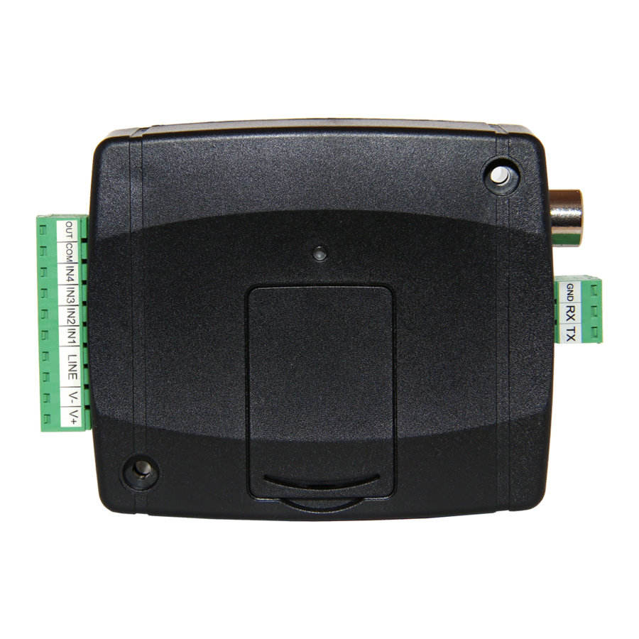
2 Connecting the terminals and putting into operation Attention! Do NOT connect the metallic parts of the GSM antenna connector or the terminals of the device directly or indirectly to the protective ground, because this may damage the device! 2.1 Connections and wiring System terminal inputs and outputs: Supply voltage 12…24V DC (min. -
Page 8: Input Wiring
Insert the SIM card in the holder. The services to be activated on the SIM card installed into the Adapter2 device should be chosen according to which services of the device you wish to use. Basically, for communication with receivers and servers it requires a SIM card with mobile Internet access that may use either public or private APN. -
Page 9: Connecting The Antenna
• You can power up the device (12-24V DC). Make sure that the power source is sufficient for the operation of the Adapter2 device. The nominal current consumption of the Adapter2 device is 120mA, however it may increase up to 500mA during communication and output control. -
Page 10: Status Led Signals
2.8 Status LED signals Normal operation, Slowly flashing green connected to the GSM or WiFi network The GSM or WiFi service is unavailable, Flashing red or system startup/restart in progress SIM card error Permanent red (only for models equipped with a modem) 2.9 Technical specification 12…24V DC Supply voltage range:... -
Page 11: Configuring The Adapter2
The latest version of the programming software is available on the manufacturer’s website (http://www.tell.hu). The Adapter2 programming software can be used to configure all Adapter2 device models. 3.1 The user interface and configuration options of the software The user interface language can be selected during installation. -
Page 12: Methods For Connecting To The Device
You can use this option if the device is connected to the cloud. Peer-to-peer: direct remote IP connection over the Internet. This option can be used if the computer running the programming software, and the SIM card installed in the Adapter2 device are in the same VPN or a private APN. -
Page 13: Configuring Directly Via Usb
3.2.2 Configuring directly via USB To start programming the device, follow the instructions below: • Open the Adapter2 programming software. • Select the USB option in the “Connection type” menu, power up the device and connect it to the computer using a USB-A to USB-B cable. -
Page 14: Remote Connecting To Devices Via Cloud Service
3.2.3 Remote connecting to devices via cloud service This connection type can be used if the Adapter2 device is connected to the cloud. For this, the APN settings should be configured in the “General” settings menu, and a SIM card with... - Page 15 Connecting to the device through the cloud: • Select the “Cloud” option in the “Connection type” menu. • If you have already registered the device in the "Device register" menu, select the device you want to connect to from the "Device Name" drop-down menu. Otherwise, you can either enter the data needed for connecting, in the corresponding fields, which will be recorded automatically in the device register using the entered device ID as the device name, when you start connecting to the device.
- Page 16 Possible error messages: Missing APN The APN is not configured. The device is unable to connect to the Internet due to an Network connection error error, faulty settings, or missing Internet service. If the APN settings are not configured in the device, or if they are wrong, you can configure this using the following SMS commands.
-
Page 17: Remote Connecting To Devices Via Peer-To-Peer Connection
SIM cards in the given APN should be enabled. The SIM card installed in the Adapter2 device you wish to connect remotely to, should have a static IP address and should be part of the given private APN, respectively VPN, just like the computer from which you wish to connect to the device. - Page 18 Connecting to the device through peer-to-peer connection: • Select the “Peer-to-peer” option in the “Connection type” menu. • If you have already registered the device in the "Device register" menu, select the device you want to connect to from the "Device Name" drop-down menu. Otherwise, you can either enter the data needed for connecting, in the corresponding fields, which will be recorded automatically in the device register using the entered device ID as the device name, when you start connecting to the device.
-
Page 19: Remote Connecting To Devices Which Are Using The Tex Protocol
“Server register” menu. TEX group ID: the CMS identifier of the Adapter2 to which you want to connect to. The TEX group ID can be configured in the device settings. Its format is: FFF (3 hexadecimal characters). -
Page 20: Remote Connecting To Devices Which Are Using The Tellmon Protocol
3.2.6 Remote connecting to devices which are using the TELLMon protocol This connection type can be used if the Adapter2 device you want to access remotely is connected to a TELLMon receiver or an MVP.next server, and it has been configured to communicate with the given server or receiver using the TELLMon protocol. - Page 21 • Click on the “Connect” button. • The Adapter2 device that communicates using the TELLMon protocol is not online continuously. The device connects to the server or receiver only when it sends a supervision message or reports an event. Therefore, after clicking on the “Connect”...
-
Page 22: Adapter2 Programming Software Usage And Feature Descriptions
Adapter2 device model and to configure and save the settings in advance offline, without connecting the device. If you wish to view the settings options of a Adapter2 device model, or to configure and save settings without connecting the device, click on the arrow found next to the “Offline device selector”... -
Page 23: Connection Type
4.1.2 Connection type In the “Connection type” menu you can select the method for connecting to the device (USB or different options for connecting over the Internet), view information about the connection process, change the admin and superadmin passwords, restart the device, and restore the factory default settings in the device. - Page 24 • Updating the firmware: By clicking on the “Firmware update” button, you can update the firmware of the device. Clicking on this button will open a new window, where you can browse the firmware file with the tf3 extension. When uploading the firmware is finished, the window that shows the progress will close automatically, and then 5 seconds later, the device will restart with the new firmware.
-
Page 25: Device Register
If needed, you can import a database exported from an earlier version of the program using the MMTool software which is included in the setup of the Adapter2 programming software. If your devices are connected to an MVP.next server and you have a registered MVP.next remote monitoring account, it is possible to read and save the data of your devices automatically in the device register. - Page 26 Function buttons available in the “Device register” menu: : update the records from database : quick remote connect to the selected device : create a shortcut on the desktop, used to connect immediately to the selected device : add new device : clone entry (duplicate) : edit entry : delete entry...
- Page 27 Device IP address: for devices with a modem, this is the IP address of the SIM card installed in the device. The peer-to-peer connection only works with a static IP used in a private APN! For a WiFi device, this is the static WAN IP address of the router to which the device is connected, or the local IP address of the device, in case that you want to access the device in the local network only.
-
Page 28: Server Register
4.1.4 Server register The server register is used for storing the contact details of the monitoring servers and receivers and to facilitate quick remote connecting to the devices. In the “Server register” menu you can record your monitoring servers and receivers, and then you can associate them with your devices in the “Device register”... - Page 29 Function buttons available in the “Server register” menu: : update the records from database : read devices from MVP.next server : add new server, receiver or network : clone entry (duplicate) : edit entry : delete entry Data stored in the server register: Server/Receiver/Network name: custom server, receiver, or network name.
- Page 30 Remote access of devices via the MVP.next server: If your devices are connected to an MVP.next server and you have a registered MVP.next remote monitoring account, it is possible to download and save the data of your devices automatically in the device register.
-
Page 31: Device Settings Menu
4.2 Device settings menu You can configure the device settings in the submenus available in the “Device settings” menu. • Changing the device settings: To change the device settings, first you must read the actual settings from the device by clicking the “Read” button in a submenu in either “Device settings”... -
Page 32: General Device Settings
4.2.1 General device settings In this menu you can configure the general settings of the device. Available options: • Reading the settings from the device: To read the settings from the device, click on the “Read” button. This will read all settings in all menus. - Page 33 • Saving settings to file: To save all device settings to file, click on the “Save to file” button. • Loading settings from file: To load saved settings from file, click on the “Load from file” button. Please note that after you make changes, you must write the settings into the device to be applied.
- Page 34 WiFi (WiFi model only): WiFi settings are available in the “General” device settings menu when you connect the WiFi product model. Configuring the WiFi settings: • Read the settings from the device by clicking on the “Read settings” button. • Select the “Scan…” option in the “WiFi network (SSID)” drop-down menu to start scanning available WiFi networks.
- Page 35 Do not fill in the account ID section with zeros! Device name: in this field you can enter a custom name for your Adapter2 device. For the PRO model, the system will use this name in the subject of e-mail notifications.
- Page 36 Internet. Configure the settings according to the requirements of the device (alarm control panel or other device) connected to the serial port of the Adapter2. Available options: baud rate, parity and stop bits.
- Page 37 GSM network after the delay configure in the “Dialing delay” section, upon picking up the receiver of the landline phone device connected to the Adapter2. When the automatic dialing function is used, the device can also be used with an alarm control panel, if an appropriate dialing delay is configured.
- Page 38 SMS forwarding daily limit: with this setting you can limit the number of SMS messages to be forwarded per day. When the configured limit is reached, the device will not forward new incoming SMS messages for 24 hours. After 24 hours the message counter resets automatically, and incoming messages will be forwarded again up to the configured limit.
-
Page 39: Mobile Devices (Adapter2 Pro Only)
4.2.2 Mobile devices (Adapter2 PRO only) In this menu you can manage the access of mobile applications. The device supports access of up to 4 mobile devices, for which you can configure here the registration password requested upon assigning the mobile application to the device, and it is also possible to delete a mobile device if needed, i.e., to cancel its registration. - Page 40 Device manager: In case of assigning a mobile application to the Adapter2 device, receiving alerts from the device will become available through Push notification too. For this, when configuring events, you can select which of the up to 4 (PUSH1…PUSH4) assigned mobile devices you wish to receive a Push notification on when the given event occurs.
-
Page 41: Reporting Channels
In the “Reporting channels” menu you can configure the availabilities where notifications should be sent, such as monitoring servers or receivers, user phone numbers for calls and SMS sending, and e-mail addresses for notification by e-mail in case of using the Adapter2 PRO model. Available options: •... - Page 42 Protocol: select the appropriate communication protocol for the given server or receiver from the drop-down menu. Available protocols: • TELLMon (custom TELL protocol for the TELLMon receiver and the MVP.next server); • TEX (custom TELL protocol for the TEX-MVP and the TEX BASE/PRO servers); • SIA IP (SIA DC-09).
- Page 43 Phone number: the CMS phone number where you want to forward the reports via SMS. It is recommended to enter the phone number in international format (e.g.: +3630…). Message: the text of the message for backup reporting. This can be a specific custom message, or you can use the variables supported by the device, which the device will replace automatically with the data of the report received from the alarm system, as follows: $cn: event name, $cp: partition name, $cz: zone name,...
- Page 44 Regardless of this setting, when a call is received from a user phone number, a related service event is generated for which you can configure output control or notification sending. E-mail notification recipients (Adapter2 PRO only): You can configure up to 4 e-mail addresses (MAIL1 to MAIL4) to which the device will send notification upon event occurrence, according to the event settings.
-
Page 45: Notification Templates
4.2.4 Notification templates Notification templates should only be configured if reporting to CMS is needed. In this menu you can configure different templates according to which the device will send reports to CMS servers and receivers. For quick and easy setup, the device contains 2 built-in templates, named as “DEFAULT”... - Page 46 Additionally, if a reporting channel fails, the devices will keep sending supervision messages to the given server/receiver by the configured supervision sending interval to check its availability, and will send the report as soon as it becomes available. The device will no longer try to report events for which reporting failed for more than 1 hour.
-
Page 47: Inputs
4.2.5 Inputs In the “Inputs” menu you can configure the default state of the 4 contact inputs, activation sensitivity, and input restore sensitivity can also be configured. Available options: • Reading the settings from the device: To read the settings from the device, click on the “Read” button. This will read all settings in all menus. -
Page 48: Input Events
Settings: Input type: the input can be normally open (NO), or normally closed (NC). When set to NO, an input event will be generated when the open contact between the given input (IN1…IN4) and the V- terminal (or the COM terminal) becomes closed. When set to NC, an input event will be generated when the closed contact between the given input (IN1…IN4) and the V- terminal (or the COM terminal) becomes open. - Page 49 Available options: • Reading the settings from the device: To read the settings from the device, click on the “Read” button. This will read all settings in all menus. • Writing the settings into the device: After changing the settings or entering new settings, to take effect, it is necessary to write the new settings into the device by clicking on the “Write”...
- Page 50 Remote monitoring: In this section you can configure the Contact ID event code for reporting to CMS and can select one of the preconfigured notification templates for the given event. The Contact ID event code should only be configured if reporting to CMS is used, otherwise select the notification template named “EMPTY”.
- Page 51 Output: In this section you can configure the output to be controlled when the given input event occurs. Output control mode: in this section you can configure the control mode of the output. Available options: • None: the output will not be used. •...
- Page 52 $ps: the momentarily measured supply voltage value (e.g.: 13563 mV). Camera (Adapter2 PRO only): in this section you can select the IP camera which you wish to assign to the given event. IP cameras should be configured in advance in the “IP cameras” menu.
-
Page 53: Service Events
4.2.7 Service events In the “Service events” menu you can configure the custom service events of the device and notifications to be sent when a service event occurs. Service events you wish to use should be added and configured. If a service event is not added, the given event will not be generated, and the device will not send notifications related to that event. - Page 54 Available options: • Reading the settings from the device: To read the settings from the device, click on the “Read” button. This will read all settings in all menus. • Writing the settings into the device: After changing the settings or entering new settings, to take effect, it is necessary to write the new settings into the device by clicking on the “Write”...
- Page 55 - Low supply voltage: the device has built-in supply voltage monitoring function. Low supply voltage event is generated when the supply voltage level is continuously on, or drops below the configured low supply voltage threshold value, for at least 30 seconds. Low supply voltage restore event is generated when the supply voltage level is continuously on, or returns above the configured low supply voltage restore threshold value, for at least 30 seconds, after a “Low supply voltage”...
- Page 56 - Settings changed: this type of event is generated when the Superadmin user changes a protected setting, that the Admin user has no access to (which is disabled in the “Admin access” menu.) - SMS sending daily limit reached: this type of event is generated when the number of event SMS messages sent by the device on the given day reaches the value configured at the “SMS sending daily limit”...
- Page 57 Output: In this section you can configure the output to be controlled when the given service event occurs. Output control mode: in this section you can configure the control mode of the output. Available options: • None: the output will not be used. •...
- Page 58 $ps: the momentarily measured supply voltage value (e.g.: 13563 mV). Camera (Adapter2 PRO only): in this section you can select the IP camera which you wish to assign to the given event. IP cameras should be configured in advance in the “IP cameras” menu.
-
Page 59: Custom Events
4.2.8 Custom events In this menu you can configure custom events, which the device generates upon receiving a custom command by text message (SMS). You can freely configure the custom command for each event. Just like input and service events, custom events enable sending reports to remote monitoring station, notifications to users, as well as controlling the output. - Page 60 PWD: the device password can be specified using this parameter. The superadmin and admin passwords are both accepted (default superadmin password: 1234). The PWD is an optional parameter which should be used only when sending commands from phone numbers which are not configured in the device in the Reporting channels menu, in the User phone number settings section –...
- Page 61 Event: Name: custom name of the event. The name entered in this section is used for identification of the given event within the program and in the event logs. The name should not be longer than 20 characters, and the following characters cannot be used: ^ ~ < > = | $ % " '. Custom text command: enter any text command which you want to send in a text message (SMS) to the device’s phone number to generate the given custom event, and send report, notifications and execute controls configured for the given event.
- Page 62 Output: In this section you can configure the output to be controlled upon occurrence of the given custom event. Output control mode: in this section you can configure the control mode of the output. Available options: • None: the output will not be used. •...
- Page 63 $ps: the momentarily measured supply voltage value (e.g.: 13563 mV). Camera (Adapter2 PRO only): in this section you can select the IP camera which you wish to assign to the given event. IP cameras should be configured in advance in the “IP cameras” menu.
-
Page 64: Ip Cameras (Adapter2 Pro Only)
4.2.9 IP cameras (Adapter2 PRO only) In this menu you can configure the availabilities of up to 4 IP cameras with ONVIF support, which then can be assigned to events in the event settings. If e-mail notifications are configured for events, the URL of the IP camera assigned to the given events will be sent along with the messages in the given e-mails when the events occur. - Page 65 IP address and port in the URL obtained using the ONVIF camera detector program, with the external (WAN) IP address of your router and the external port, and after this enter the modified URL in the Adapter2 programming software. Example for modification of the stream URL, if using only one camera: Original URL: rtsp://192.168.1.240:554/cam/realmonitor?channel=1&subtype=0&unicast=true&proto=Onvif...
-
Page 66: Voice Messages
4.2.10 Voice messages In this menu you can upload audio files used for notifications via voice calls, and you can also configure a custom name for each voice message. The audio files can be uploaded in mp3 or wav format. Uploaded audio files are automatically converted by the software into the format appropriate for the device. - Page 67 • Editing the name of an audio file: To edit the name of the selected audio file, click on the “Edit” button. • Uploading an audio file: To upload an audio file to the selected voice message, click on the “Audio file upload”...
-
Page 68: Admin Access
4.2.11 Admin access In this menu you can configure permissions for the Admin user to access protected settings. The Admin user can only modify the settings enabled in the list. The Admin access options can only be configured by the Superadmin. The settings that don’t have a checkmark, i.e. -
Page 69: Advanced Settings
4.2.11 Advanced settings In this menu you can configure advanced settings which affect communication to CMS over DTMF-based voice call and the in-call volume for calls to users (siren tone, voice messages). Special DTMF communication parameters can be configured to adjust signals in case of experiencing problems with reporting to CMS over DTMF-based voice call. - Page 70 • Searching mobile operators: To search mobile operators, click on the “Search operators” button. This is needed when you want to select a certain operator in the “Operator selection” drop-down menu to force the modem to use the given operator. After clicking on this button, the device will restart the modem and will reconnect to the mobile network to start operator searching.
- Page 71 3G network usage is supported by the 3G(A).IN4.R1 and the 4G(A).IN4.R1 model of the Adapter2 only! LTE network usage is supported by the 4G(A).IN4.R1 model only! Use automatic selection upon network errors: if this option is enabled, the device will select an available network when service error occurs, even if the use of a specific network is selected in the settings (2G, 3G, or LTE).
-
Page 72: Alarm System Events Menu
4.3 Alarm system events menu In this menu group you can configure settings of events sent by the alarm system. 4.3.1 Alarm system events The “Alarm system events” menu can be used to filter Contact-ID event codes received from the alarm control panel connected to the device. - Page 73 The device chooses in each case the added alarm system event filter which matches best the event code received from the alarm control panel. For example if it finds two added alarm system event filters at which the event type, the event code and the partition matches the event received from the alarm control panel, but at one of them the zone section matches too, while at the other one the zone section is filled in with "...
- Page 74 Event: Name: custom name of the event. The name entered in this section is used for identification of the given event within the program and in the event logs. The name should not be longer than 20 characters, and the following characters cannot be used: ^ ~ < > = | $ % " '. Type: the type of the event.
- Page 75 Push notification (Adapter2 PRO only): in this section you can select the mobile devices to which Push notification should be sent when the given event occurs. The mobile devices should be configured in advance in the “Mobile devices”...
- Page 76 $ps: the momentarily measured supply voltage value (e.g.: 13563 mV). Camera (Adapter2 PRO only): in this section you can select the IP camera which you wish to assign to the given event. IP cameras should be configured in advance in the “IP cameras” menu.
-
Page 77: Custom Event Code Names
4.3.2 Custom event code names The table found in the “Custom event code names” menu contains the default Contact ID event codes and event names. If needed, you can rename the events generated by the connected alarm control panel, or add new custom events if your alarm control panel would use an evet code that is missing from the event code table of the device. - Page 78 Available options: • Reading the settings from the device: To read the settings from the device, click on the “Read” button. This will read all settings in all menus. • Writing the settings into the device: After changing the settings or entering new settings, to take effect, it is necessary to write the new settings into the device by clicking on the “Write”...
- Page 79 The structure requirements of the CSV file to be imported: The program considers the first line of the CSV file as the header. Therefore, it will not process the firs line! The file should contain the entries starting from the second line. The line should start with the 3-digit event code, followed by the event type indicator (0=zone related event, 1=user related event), the custom new event name, and then the custom restore event name, each separated by a semicolon.
-
Page 80: Custom User Names
4.3.3 Custom user names In the “Custom user names” menu you can associate names with users configured in the alarm control panel, by the user number. The device can use the custom user names configured here in text-notifications (SMS, Push, e-mail). The $cz variable written in the text of the message will be replaced by the device automatically with the user name associated with the user number received from the alarm control panel, when the device reports a user related event. - Page 81 Available options: • Reading the settings from the device: To read the settings from the device, click on the “Read” button. This will read all settings in all menus. • Writing the settings into the device: After changing the settings or entering new settings, to take effect, it is necessary to write the new settings into the device by clicking on the “Write”...
- Page 82 The structure requirements of the CSV file to be imported: The program considers the first line of the CSV file as the header. Therefore, it will not process the firs line! The file should contain the entries starting from the second line. The line should start with the 3-digit user number, followed by a semicolon, and then the user name.
-
Page 83: Custom Partition Names
4.3.4 Custom partition names In the “Custom partition names” menu you can associate names with partitions configured in the alarm control panel, by the partition number. The device can use the custom partition names configured here in text-notifications (SMS, Push, e-mail). The $cp variable written in the text of the message will be replaced by the device automatically with the partition name associated with the partition number received from the alarm control panel, when sending the message. - Page 84 Available options: • Read the settings from the device: To read the settings from the device, click on the “Read” button. This will read all settings in all menus. • Write the settings into the device: After changing the settings or entering new settings, to take effect, it is necessary to write the new settings into the device by clicking on the “Write”...
- Page 85 The structure requirements of the CSV file to be imported: The program considers the first line of the CSV file as the header. Therefore, it will not process the firs line! The file should contain the entries starting from the second line. The line should start with the 2-digit partition number, followed by a semicolon, and then the partition name.
-
Page 86: Custom Zone Names
4.3.5 Custom zone names In the “Custom zone names” menu you can associate names with zones configured in the alarm control panel, by the zone number. The device can use the custom zone names configured here in text-notifications (SMS, Push, e-mail). The $cz variable written in the text of the message will be replaced by the device automatically with the zone name associated with the zone number received from the alarm control panel, when the device reports a zone related event. - Page 87 Available options: • Reading the settings from the device: To read the settings from the device, click on the “Read” button. This will read all settings in all menus. • Writing the settings into the device: After changing the settings or entering new settings, to take effect, it is necessary to write the new settings into the device by clicking on the “Write”...
- Page 88 The structure requirements of the CSV file to be imported: The program considers the first line of the CSV file as the header. Therefore, it will not process the firs line! The file should contain the entries starting from the second line. The line should start with the 3-digit zone number, followed by a semicolon, and then the zone name.
-
Page 89: Device Status Menu
4.4 Device status menu 4.4.1 Status monitoring The “Status monitoring” menu provides information on actual system status. Please note that for faster communication, in case of remote connection some of the options are not available. Status information loads and refreshes automatically only when connected through USB. The system logs are shown in the window on the right hand side, which provides information about the internal processes of the device and communication. - Page 90 Counters: • System time: the system date and time. • IP uptime: elapsed time since the device has last connected to the Internet. • Device uptime: elapsed time since the device has been powered up. • GSM uptime: elapsed time since the device has last connected to the GSM network. •...
-
Page 91: Event Monitoring
• Activate output: You can activate the output (OUT) by clicking on this button. The output remains activated until deactivated manually or by an event, which has been configured to control the given output in a way that deactivates it, or a power loss occurs. •... - Page 92 Available options: • Start monitoring: By clicking on this button, the program will download the stored and will display new events as well. By clicking on the arrow next to this button, you can choose from the drop-down menu, how many events you want to see in the list: last 10, 20 or all. •...
-
Page 93: System Event Logs
4.4.3 System event logs Events related to device operation are shown in the system event logs. To download the system event logs from the device, open the “Read” drop-down menu, select how many events you want to download from the latest ones (10, 20 or all), and then click on the “Read”... -
Page 94: Software Settings Menu
4.5 Software settings menu 4.5.1 Settings In the “Settings” menu you can change the user interface skin and language. Available options: • Restore default layout: To restore the user interface default layout, click on the “Restore default layout” button. User interface: Theme: the user interface appearance can be changed using this dropdown-menu. -
Page 95: About
Show the QR code containing the device ID in the Status monitoring menu: if this option is enabled, the QR code that contains the device ID will be shown in the “Status monitoring” menu. This is used by the manufacturer to record devices produced. 4.5.2 About The “About”... -
Page 96: Transparent Serial Port
Adapter2 device and the Remote Serial Client software. For this, the serial port of the Adapter2 should be connected to the serial port of the alarm control panel, and the programming software of the alarm system connects to the virtual serial port created by the Remote Serial Client software. -
Page 97: Paradox Alarm Systems
TELL offers its own level driver interface produced for this purpose. Connect the serial port output of the level driver interface to the serial port of the Adapter2, then link the level driver interface with the alarm control panel using the supplied special cable, as shown in the figure above. - Page 98 Remote Serial Client software. This client software ensures the connection between the PC and the Adapter2 device, as well as it creates a virtual serial port for the programming software of the alarm system.
- Page 99 Example for selecting the serial communication port in the Babyware programming software: For Spectra alarm control panels: Baud rate=9600 baud For EVO alarm control panels: Baud rate=57600 baud Start connecting: Then the programming software will open the serial port and will establish the connection with the alarm control panel.
- Page 100 After you have finished remote programming the alarm control panel, you can delete the created virtual serial port by clicking on the “Delete port” button.
-
Page 101: Dsc Alarm Systems
5.1.2 DSC alarm systems • Installation: Connect the supplied special cable to the serial port of the Adapter2 device as shown in the figure above, then plug it onto the alarm control panel. • Software settings: Configure the serial port settings in the “Serial port” section of the “General” menu, in the... - Page 102 Remote Serial Client software. This client software ensures the connection between the PC and the Adapter2 device, as well as it creates a virtual serial port for the programming software of the alarm system.
- Page 103 Start connecting: Then the programming software will open the serial port and will establish the connection with the alarm control panel. After you finished remote programming the alarm control panel, you can delete the created virtual serial port by clicking on the “Delete port” button.
-
Page 104: Premier And Premier Elite Alarm Systems
TELL offers its own level driver interface produced for this purpose. Connect the serial port output of the level driver interface to the serial port of the Adapter2, then link the level driver interface with the alarm control panel using the supplied special cable, as shown in the figure above. - Page 105 Remote Serial Client software. This client software ensures the connection between the PC and the Adapter2 device, as well as it creates a virtual serial port for the programming software of the alarm system.
- Page 106 Example for selecting the serial communication port in the Wintex programming software: Then the programming software will open the serial port and will establish the connection with the alarm control panel. After you have finished remote programming the alarm control panel, you can delete the created virtual serial port by clicking on the “Delete port”...
-
Page 107: Bentel Alarm Systems
5.1.4 Bentel alarm systems • Installation: Connect the supplied special cable to the serial port of the Adapter2 device as shown in the figure above, then plug it onto the alarm control panel. • Software settings: Configure the serial port settings in the “Serial port” section of the “General” menu, in the... - Page 108 Remote Serial Client software. This client software ensures the connection between the PC and the Adapter2 device, as well as it creates a virtual serial port for the programming software of the alarm system.
- Page 109 Start connecting: Then the programming software will open the serial port and will establish the connection with the alarm control panel. After you finished remote programming the alarm control panel, you can delete the created virtual serial port by clicking on the “Delete port” button.
-
Page 110: Inim Alarm Systems
5.1.5 Inim alarm systems • Installation: Connect the supplied special cable to the serial port of the Adapter2 device as shown in the figure above, then plug it onto the alarm control panel. • Software settings: Configure the serial port settings in the “Serial port” section of the “General” menu, in the... - Page 111 Remote Serial Client software. This client software ensures the connection between the PC and the Adapter2 device, as well as it creates a virtual serial port for the programming software of the alarm system.
- Page 112 Example for selecting the serial communication port in the Ability Suite programming software, in the “Settings / Application settings” menu: Example for selecting the serial communication port in the Smart League programming software, in the “Settings / Application settings” menu:...
- Page 113 Start connecting with the Ability Suite programming software: Start connecting with the Smart League programming software: Then the programming software will open the serial port and will establish the connection with the alarm control panel.
-
Page 114: Arming And Disarming The Alarm Control Panel Through The Mobile Application
“Pulse control” option, and then apply the changes. You can leave the duration of control at the default value (1 second). To arm and disarm the alarm control panel, activate the output of the Adapter2 PRO in the mobile application. Each output activation creates a short circuit between the OUT and COM terminals for the configured period of time (1 second), and then reverts to default open state automatically. -
Page 115: Updating The Firmware
You can update the firmware of your Adapter2 device locally via USB, or remotely via the Internet. You can find the firmware file or the desktop update application needed for the update on the manufacturer's website (https://tell.hu/en) in the product downloads section. -
Page 116: Restoring The Factory Default Settings
The following methods are available for updating the Adapter2 device’s firmware remotely: • Updating in case that you use a TELLMon receiver: Directly from the TELLMon receiver, by loading the firmware file in the receiver. Using the programming software, via the TELLMon protocol.
Need help?
Do you have a question about the Adapter2 and is the answer not in the manual?
Questions and answers