
Summary of Contents for G.S.M Activate AUTO DIALLER PLUS
- Page 1 GSM 3G AUTO DIALLER PLUS Control and Monitoring from your mobile phone www.gsm-activate.co.uk MODEL NUMBER 3GADV2 Page 1...
- Page 2 Contents ● 2 - Contents. ● 3 - Product Information. - Specification. ● 4 - PCB Reference. ● 5 - Installing Your Simcard. - Signal Strength Test. ● 6 - Storing and Deleting Contact Numbers. ● 7 - How to Store Input Text Messages. - How to Set Phone Call Alerts and Text Messages.
-
Page 3: Product Information
Product Information A Multi Purpose GSM Auto Dialler with 2G and 3G capabilities. It is compatible with all alarm panels with negative triggering through two inputs as well as having relay outputs for switching on external devices, temperature monitoring, mains failure monitoring with battery backup and alarm input for PIR’s and IR beams. -
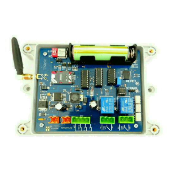
Page 4: Dip Switch
PCB Reference IMPORTANT - PLEASE READ PLEASE MAKE SURE YOU DISCONNECT THE POWER FROM POWER INPUT AND REMOVE THE BATTERY LINK WHEN YOU FIT THE SIMCARD AND YOU PLACE THE SIMCARD WITH THE CLIPPED CORNER FACING OUT WARDS. PLEASE SEE PICTURE ABOVE. Signal LED (blue) - The blue LED flashes once per second to indicate when a signal has... -
Page 5: Installing Your Simcard
Installing your simcard New SIM cards will need registering before they can be used. Full details of how this is done can normally be found in the SIM card pack. It will normally require that the SIM card is inserted into a mobile phone, a number dialed and instructions followed. While the SIM is in the mobile phone it would be a good time to disable call diverts, ring back and to disable features such as voicemail and text alerts. - Page 6 Programming Contact Numbers The 3G Auto Dialler has two inputs for a connection to electrical equipment plus separate hardware for temperature, tilt, mains failure and external sensing. When these are triggered the unit will call or text up to 3 separate numbers which can be stored on to the unit. To programme the numbers you want to use, follow the examples below by sending the text message command to the simcard in the auto dialler.
- Page 7 How to program the (sms) text message You can now change the alarm message to one of your choosing. To change the message send the text command as follows. #MESS1=YOURMESSAGE# - This sets your custom message to input 1 #MESS2=YOURMESSAGE# - This sets your custom message to input 2 The default message is ALARM 1 and ALARM 2 Note - You can only use a maximum of 16 characters including spaces for your customised...
- Page 8 How to Use the Relay Outputs The 3G Auto Dialler has two relay outputs which can be used to switch on external electric devices such as lighting, sirens etc. Relay 1 is independent and can be activated by sms message Relay 2 is also independent but also linked to the inputs and will go on for 30 seconds when an input is triggered Activation by SMS Text Message (Relay 1 )
-
Page 9: Battery Backup
Mains Failure Alarm By connecting to mains power via a 9/24v power supply the auto dialler can act as a mains failure alarm. It will monitor the power connected to the power input and send a text message alert if power is disconnected. When the power is disconnected for a period of 4 minutes, you will receive a text message alert POWER LOSS. -
Page 10: Temperature Monitoring
Temperature Monitoring The Auto dialler has its own temperature sensor which can monitor temperatures from -30 up to +99 degrees centigrade. Additionally you can monitor temperatures at -40 and -50 degrees centigrade. The temperature sensor can be used in two ways. 1: To read the current temperature. - Page 11 Quick Programming Page 11...
- Page 12 Inputs 1 & 2 Inputs 1 & 2 - Automatically Reset They are triggered by a negative pulse eg: pulled to the ground for a period of not less than one second. The image (to the left) is a typical application of how to connect the unit to an alarm panel.
- Page 13 I M P O R T A N T I N S TA L L E R N O T E S When installing the aerial antenna cable please ensure that the cable leaves the box by the shortest possible route and is not coiled up and left inside the box. Do not stick the aerial onto any metal surface.
- Page 14 DIAGRAMS For more technical support please browse the FAQ’s on our website www.gsm-activate.co.uk or alternatively email our technical support team at technical@gsm-activate.co.uk and we will reply or call back within 24 hours Monday - Friday. 03/10/18 AD Page 14...
Need help?
Do you have a question about the AUTO DIALLER PLUS and is the answer not in the manual?
Questions and answers