Table of Contents
Advertisement
9201-B San Mateo Blvd N.E.
Albuquerque, New Mexico 87113 U.S.A.
CAGE: 6PC31
Telephone: 855-250-7027 (Toll Free U.S.A./Canada)
Telephone: 505-903-6148 (International Direct)
Website:
www.BendixKing.com/support
KGX 150/130 Transceivers and Receivers
Part Number
89000016-130
89000016-131
89000016-150
89000016-151
Export Control
This document contains technical data and is subject to U.S. export regulations. These commodities, technology, or
software were exported from the United States in accordance with the export administration regulations. Diversion contrary
Publication Number D201405000059, Revision 1
© Honeywell International Inc. Do not copy without express permission of Honeywell.
System Installation Manual
Legal Notice
to U.S. law is prohibited.
ECCN: 7E994.
CAGE
6PC31
6PC31
6PC31
6PC31
Page T-1
Initial 19 Jan 2015
Revised 22 Dec 2016
Advertisement
Chapters
Table of Contents

Related Manuals for BENDIXKing KGX 150

Summary of Contents for BENDIXKing KGX 150
- Page 1 9201-B San Mateo Blvd N.E. Albuquerque, New Mexico 87113 U.S.A. CAGE: 6PC31 Telephone: 855-250-7027 (Toll Free U.S.A./Canada) Telephone: 505-903-6148 (International Direct) Website: www.BendixKing.com/support System Installation Manual KGX 150/130 Transceivers and Receivers Part Number CAGE 89000016-130 6PC31 89000016-131 6PC31 89000016-150 6PC31...
- Page 2 SYSTEM INSTALLATION MANUAL 89000016 Proprietary Information Honeywell - Confidential THIS COPYRIGHTED WORK AND ALL INFORMATION ARE THE PROPERTY OF HONEYWELL INTERNATIONAL INC., CONTAIN TRADE SECRETS AND MAY NOT, IN WHOLE OR IN PART, BE USED, DUPLICATED, OR DISCLOSED FOR ANY PURPOSE WITHOUT PRIOR WRITTEN PERMISSION OF HONEYWELL INTERNATIONAL INC.
- Page 3 SYSTEM INSTALLATION MANUAL 89000016 License Agreement or will terminate simultaneously with the termination or expiration of your applicable product support agreement, authorized repair facility agreement, or your formal designation as a third party service provider. Upon termination of this License Agreement, you will return these Materials to Honeywell without retaining any copies and will have one of your authorized officers certify that all Materials have been returned with no copies retained.
- Page 4 SYSTEM INSTALLATION MANUAL 89000016 Copyright - Notice Copyright 2015, 2016 Honeywell International Inc. All rights reserved. Honeywell is a registered trademark of Honeywell International Inc. All other marks are owned by their respective companies. THIS IS THE CMM FOSI - DATE: 20101217 Page T-4 22 Dec 2016 ©...
- Page 5 89000016 TRANSMITTAL INFORMATION REVISION NUMBER 1 DATED 22 DEC 2016 TO HOLDERS OF KGX 150/130 TRANSCEIVERS AND RECEIVERS SIM PUB. NO. D201405000059 ISSUED FOR USE IN SUPPORT OF THE FOLLOWING: Table TI-1 shows the applicable components. Table TI-1. Applicable Components...
- Page 6 Paragraph 1.A. Added a new last sentence in Step (3). Page 1001 Paragraph 3.A. Updated KGX descriptions in Table 1001. Page 1004 Paragraph 4.A. Added new Garmin and BendixKing part numbers and changed the model number for the Garmin manufacturer in Table 1007. Page 1004 Paragraph 5.
- Page 7 SYSTEM INSTALLATION MANUAL 89000016 Table of Highlights (Cont) Task/Page Description of Change Effectivity Page 1011 Paragraph 10.B. Changed I/O for J1-43 from I to O in Table 1012. Page 1013 Paragraph 10.E. Added RS-232 and note to serial Port 6 data in Step (2) and in Table 1015.
- Page 8 SYSTEM INSTALLATION MANUAL 89000016 Table of Highlights (Cont) Task/Page Description of Change Effectivity Page 2001 Paragraph 1. Replaced Paragraphs 1 thru 10 with new Paragraphs 1 thru 6. The subsequent paragraphs are renumbered. Replaced Figures 2001 thru 2008. Added Figures 2009 thru 2012 and applicable text and tables. Page 3001 Paragraph 1.A.
- Page 9 SYSTEM INSTALLATION MANUAL 89000016 Table of Highlights (Cont) Task/Page Description of Change Effectivity Page 3021 Figure 3008. Added Tera Term WiFi Connection Settings Initial MPI Connection graphic. Page 3021 Figure 3009. Updated graphic to include the latest data. Page 3022 Paragraph 4.C.
- Page 10 SYSTEM INSTALLATION MANUAL 89000016 Table of Highlights (Cont) Task/Page Description of Change Effectivity Page 3035 Figure 3034. Updated graphic to include the latest data. Page 3036 Figure 3035. Updated graphic to include the latest data. Page 3036 Figure 3036. Updated graphic to include the latest data. Page 3037 Figure 3037.
- Page 11 SYSTEM INSTALLATION MANUAL 89000016 Table of Highlights (Cont) Task/Page Description of Change Effectivity Page 4002 Paragraph 3.A. Added WARNING display data in Step (1). Updated Table 4003 and Table 4004. Page 5002 Paragraph 2.A. Table 5002: Changed altitude from 50,000 feet (15, 240 m) to 35,000 feet (10,668 m).
- Page 12 SYSTEM INSTALLATION MANUAL 89000016 Blank Page EFFECTIVITY Page TI-8 22 Dec 2016 © Honeywell International Inc. Do not copy without express permission of Honeywell.
- Page 13 SYSTEM INSTALLATION MANUAL 89000016 RECORD OF REVISIONS For each revision, write the revision number, revision date, date put in the manual, and your initials in the applicable column. NOTE: Refer to the Revision History in the TRANSMITTAL INFORMATION section for revision data. EFFECTIVITY Page RR-1 22 Dec 2016...
- Page 14 SYSTEM INSTALLATION MANUAL 89000016 Blank Page EFFECTIVITY Page RR-2 22 Dec 2016 © Honeywell International Inc. Do not copy without express permission of Honeywell.
- Page 15 SYSTEM INSTALLATION MANUAL 89000016 RECORD OF TEMPORARY REVISIONS Instructions on each page of a temporary revision tell you where to put the pages in your manual. Remove the temporary revision pages only when discard instructions are given. For each temporary revision, put the applicable data in the record columns on this page.
- Page 16 SYSTEM INSTALLATION MANUAL 89000016 Blank Page EFFECTIVITY Page RTR-2 22 Dec 2016 © Honeywell International Inc. Do not copy without express permission of Honeywell.
- Page 17 Refer to Table INTRO-2 for other applicable service information documents not listed in the Service Bulletin List. Service Bulletin / Date Put in Revision Number Title Modification Manual 89000016-34-0001 NAVIGATION - KGX 150/130 TRANSCEIVERS 22 Dec 2016 (D201603000071) AND RECEIVERS AUTOMATIC DEPENDENT SURVEILLANCE BROADCAST (ADS-B) UNIVERSAL ACCESS TRANSMITTERS (UAT) - Software Upgrade Service Bulletin EFFECTIVITY...
- Page 18 SYSTEM INSTALLATION MANUAL 89000016 Blank Page EFFECTIVITY Page SBL-2 22 Dec 2016 © Honeywell International Inc. Do not copy without express permission of Honeywell.
- Page 19 SYSTEM INSTALLATION MANUAL 89000016 LIST OF EFFECTIVE PAGES Subheading and Page Date Subheading and Page Date Title TC-8 22 Dec 2016 TC-9 22 Dec 2016 22 Dec 2016 TC-10 22 Dec 2016 22 Dec 2016 TC-11 22 Dec 2016 22 Dec 2016 TC-12 22 Dec 2016 22 Dec 2016...
- Page 20 SYSTEM INSTALLATION MANUAL 89000016 LIST OF EFFECTIVE PAGES (Cont) Subheading and Page Date Subheading and Page Date * 22 Dec 2016 * 22 Dec 2016 1009 3003 * 22 Dec 2016 * 22 Dec 2016 1010 3004 * 22 Dec 2016 1011 22 Dec 2016 3005...
- Page 21 SYSTEM INSTALLATION MANUAL 89000016 LIST OF EFFECTIVE PAGES (Cont) Subheading and Page Date Subheading and Page Date * 22 Dec 2016 * 22 Dec 2016 3042 5002 3043 22 Dec 2016 5003 22 Dec 2016 3044 22 Dec 2016 5004 22 Dec 2016 * 22 Dec 2016 3045...
- Page 22 SYSTEM INSTALLATION MANUAL 89000016 Blank Page EFFECTIVITY Page LEP-4 22 Dec 2016 © Honeywell International Inc. Do not copy without express permission of Honeywell.
-
Page 23: Table Of Contents
BendixKing Customer Support ........ - Page 24 KGX Electrical Connections (All Models) ..........1009 KGX 150/130 Transceivers and Receivers Interface - Pinout ..... 1009 10.
- Page 25 15. GPS Antenna Installation (KGX 150 Series Only) ....... . .
- Page 26 SYSTEM INSTALLATION MANUAL 89000016 TABLE OF CONTENTS (Cont) LIST OF SECTIONS (Cont) Title Page General ................. . 2019 Equipment Compatibility and Functions .
- Page 27 SYSTEM INSTALLATION MANUAL 89000016 TABLE OF CONTENTS (Cont) LIST OF SECTIONS (Cont) Title Page Local Voltage Supply Test ............. 3056 KGX Control Panel Altitude Encoder Calibration .
- Page 28 SYSTEM INSTALLATION MANUAL 89000016 TABLE OF CONTENTS (Cont) LIST OF SECTIONS (Cont) Title Page Parts and Equipment ..............8002 Installation .
- Page 29 KGX 150/130 Transceivers and Receivers ........
- Page 30 SYSTEM INSTALLATION MANUAL 89000016 TABLE OF CONTENTS (Cont) LIST OF FIGURES (Cont) Figure Description Page 3004 Reverse Video Examples when KGX Control Panel is in External Control Mode . . 3003 3005 ADS-B MPI Screenshot ..............3018 3006 Tera Term Terminal Setup .
- Page 31 SYSTEM INSTALLATION MANUAL 89000016 TABLE OF CONTENTS (Cont) LIST OF FIGURES (Cont) Figure Description Page 3035 “set acsize” Command ..............3036 3036 “set uatant”...
- Page 32 SYSTEM INSTALLATION MANUAL 89000016 TABLE OF CONTENTS (Cont) LIST OF FIGURES (Cont) Figure Description Page 3065 GPS NAC Velocity Display ............. . . 3052 3066 Aircraft Length Display .
- Page 33 KGX 150/130 Installation Kit, PN 89000016-004 ........
- Page 34 SYSTEM INSTALLATION MANUAL 89000016 TABLE OF CONTENTS (Cont) LIST OF TABLES (Cont) Table Description Page 2001 System Interconnect Diagrams ............2001 2002 Equipment Specific Wiring Diagrams .
- Page 35 SYSTEM INSTALLATION MANUAL 89000016 TABLE OF CONTENTS (Cont) LIST OF TABLES (Cont) Table Description Page 4001 Troubleshooting Guide ..............4001 4002 UAT Status LED/Discrete Fault Indications .
- Page 36 SYSTEM INSTALLATION MANUAL 89000016 Blank Page EFFECTIVITY Page TC-14 22 Dec 2016 © Honeywell International Inc. Do not copy without express permission of Honeywell.
-
Page 37: Introduction
SYSTEM INSTALLATION MANUAL 89000016 INTRODUCTION How to Use This Manual General This publication gives maintenance instructions for the equipment shown on the Title page. Standard maintenance procedures that technicians must know are not given in this manual. This publication is written in agreement with the ATA Specification. Warnings, cautions, and notes in this manual give the data that follows: •... - Page 38 SYSTEM INSTALLATION MANUAL 89000016 Figure INTRO-1. (Sheet 1 of 2) Geometric Tolerance Symbols EFFECTIVITY Page INTRO-2 22 Dec 2016 © Honeywell International Inc. Do not copy without express permission of Honeywell.
- Page 39 SYSTEM INSTALLATION MANUAL 89000016 Figure INTRO-1. (Sheet 2 of 2) Geometric Tolerance Symbols EFFECTIVITY Page INTRO-3 22 Dec 2016 © Honeywell International Inc. Do not copy without express permission of Honeywell.
-
Page 40: Units Of Measure
SYSTEM INSTALLATION MANUAL 89000016 The symbols in Figure INTRO-2 show ESDS and moisture sensitive devices. Figure INTRO-2. (Sheet 1 of 1) Symbols Units of Measure Measurements, weights, temperatures, dimensions, and other values are expressed in the USMS followed by the appropriate SI metric units in parentheses. Some standard tools or parts such as drills, taps, bolts, nuts, etc. -
Page 41: Bendixking Customer Support
Honeywell/Vendor Publications Honeywell publications related to the content of this manual are shown in the list that follows: • Pub. No. D201405000060, BendixKing KGX 150/130 ADS-B Certified Transceivers and Receivers Pilot’s Guide • ATA No. 20-00-03 (Pub. No. A09-1100-004), Standard Repair Procedures for Honeywell Avionics Equipment Instruction Manual. - Page 42 SYSTEM INSTALLATION MANUAL 89000016 Acronyms and non-standard abbreviations used in this publication are as follows. List of Acronyms and Abbreviations Term Full Term µs microsecond advisory circular air data computer automatic direction finder ADS-B automatic dependent surveillance-broadcast altitude/air data sensor amplitude modulation ampere ANSI...
- Page 43 SYSTEM INSTALLATION MANUAL 89000016 List of Acronyms and Abbreviations (Cont) Term Full Term ESDS electrostatic discharge sensitive estimated time of arrival ETSO European technical standard order end-of-text end-of-transmission equipment under test Fahrenheit Federal Aviation Administration Federal Aviation Regulation Federal Communications Commission FIS-B flight information service-broadcast Flight Management System...
- Page 44 SYSTEM INSTALLATION MANUAL 89000016 List of Acronyms and Abbreviations (Cont) Term Full Term in-Hg inches of mercury internet protocol kilo kBaud kilobaud kilogram kilometer local area network liquid crystal display light-emitting diode m/sec meters per second meter milliampere maximum METAR meteorological terminal air report megahertz minimum...
- Page 45 SYSTEM INSTALLATION MANUAL 89000016 List of Acronyms and Abbreviations (Cont) Term Full Term power switching unit Pub. publication power quantity RAIM receiver autonomous integrity monitering radio frequency resolution instruction RTCA Radio Technical Commission for Aeronautics request-to-send receive SATCOM satellite communication SBAS S-band antenna switch International System of Units...
-
Page 46: Service Information Documents
Manual D201608000055 KGX Series, PN 89000016-130, -131, -150, and -151 22 Dec 2016 - Software Release 001H, Added Compatibility with BendixKing KSN 765/770 as a Global Positioning System (GPS) Input Source EFFECTIVITY Page INTRO-10 22 Dec 2016 © Honeywell International Inc. Do not copy without express permission of Honeywell. -
Page 47: General Information
SIGMETs, etc.) information, system health/status, etc. are output on multiple configured serial links and/or discrete signals to be connected to pilot displays. In Figure 1, the installation shows a display controller, KGX 150 transceiver, two UAT antennas, and a GPS antenna. Additionally, connections are shown to an external altitude sensor (shared with the transponder), the transponder suppression bus, and an air/ground detection switch. - Page 48 SYSTEM INSTALLATION MANUAL 89000016 Refer to Figure 1 and Figure 2 for a typical installation. These figures also depict installations using an aircraft mounted KGX WiFi module in place of a dedicated MPI port. This allows traffic and weather data to be shared with a portable electronic device in flight, and can be used to simplify system configuration during maintenance activities.
- Page 49 SYSTEM INSTALLATION MANUAL 89000016 Figure 2. (Sheet 1 of 1) Typical KGX 150R/130R Receiver Installation The main difference between installations is the receiver installation does not require any connections to a transponder or transponder transmit control and is not required to obtain pressure altitude data from the same altitude sensor used by the transponder.
-
Page 50: Kgx 150/130 Features
LEDs, configurable serial interfaces (controller input, GPS input/output, altitude/air data input, TCAS input, multiple display outputs, and maintenance port interface), Discrete input/output, and a personality module interface. A short summary of the KGX 150/130 transceiver and receiver features follows. -
Page 51: Kgx Control Panel (Optional)
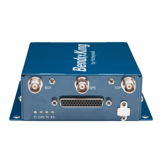
SYSTEM INSTALLATION MANUAL 89000016 Figure 3. (Sheet 1 of 1) KGX 150/130 Transceivers and Receivers KGX Control Panel (Optional) Installations where the transponder and/or display can’t give the required control and status, the KGX control panel can optionally be used to control the UAT transmitter and display status. -
Page 52: Uat Antenna Requirements
Input Power It receives low-voltage power from the KGX 150/130 transceivers. Serial Interface An RS-485 serial data link is used to connect the KGX control panel to the KGX 150/130 transceivers. Remote On/Off System on/off power is controlled with the mode selection knob. -
Page 53: Gps Antenna Requirements
TSO-C145c Class Beta 2, 3, 4 navigation sensors and avoids the need for a GPS antenna change at that time. The performance of the KGX 150 series internal GPS is affected by the gain, noise figure, impedance, and frequency selectivity characteristics of the antenna. The KGX series must only be used with the recommended antenna and cable. -
Page 54: Kgx Control Panel
SYSTEM INSTALLATION MANUAL 89000016 Table 2. KGX 150/130 Transceivers and Receivers Leading Particulars (Cont) Characteristic Specification Transmitter power 40 watts MAX at antenna after 2-dB connector/cable losses Receiver sensitivity 99 dBm Refer to Table 3 for the avionics interfaces. Table 3. Avionics Interfaces... - Page 55 SYSTEM INSTALLATION MANUAL 89000016 Table 4. KGX Control Panel Leading Particulars (Cont) Characteristic Specification Power requirements 5.5 to 10 VDC, 0.3 AMP MAX at 6.5 VDC, powered by the KGX Interfaces Type: RS-485 I/O • KGX control panel RS-232 output •...
- Page 56 SYSTEM INSTALLATION MANUAL 89000016 Blank Page EFFECTIVITY Page 10 22 Dec 2016 © Honeywell International Inc. Do not copy without express permission of Honeywell.
- Page 57 Mode A and IDENT without increased pilot workload. Transponders with serial control data out capability must be connected through a KGX 150/130 transceiver serial port to control Mode A code and IDENT. Mode A/C transponders without serial control data out can use the...
- Page 58 89000016-017 WiFi module installation kit Installation Kits The items included in the KGX installation kit are listed in Table 1002. Table 1002. KGX 150/130 Installation Kit, PN 89000016-004 Description DB-44 male crimp connector DB-44 backshell Crimp pin AWG 24 to 28 The KGX control panel has an installation kit included.
- Page 59 SYSTEM INSTALLATION MANUAL 89000016 Table 1003. KGX Control Panel and Installation Kit, PN 89000016-001 (Cont) Item Description Connector accessory backshell nine-way D-Sub three-way entry 4-40UN jackscrew Connector standard mount nine-way D-receptacle to M24308 Crimp socket contact wire size AWG 20 to 24 The items included in the optional personality module and installation kit, PN 89000016-006, are listed in Table 1004.
- Page 60 KSN 765/770 Safety Navigator 066-01204-1101 066-01213-0101 066-01213-1101 List of Other Approved WAAS GPS Antennas The KGX 150 series, PN 89000016-150 or -151, can be installed with the WAAS GPS antennas summarized in Table 1008. Table 1008. Other Approved WAAS GPS Antennas Manufacturer Model/Description...
- Page 61 SYSTEM INSTALLATION MANUAL 89000016 The FT -9000 ramp tester kit part number can be ordered as an optionaI item using the part number specified in Table 1009. Table 1009. FT-9000 RAMP Tester Kit Part Number Description Quantity 87579-00 FT-9000 ADS-B RAMP Tester Kit Equipment Mounting KGX Control Panel Mounting The KGX control panel must be mounted rigidly in the aircraft panel.
- Page 62 SYSTEM INSTALLATION MANUAL 89000016 Figure 1001. (Sheet 1 of 1) KGX Control Panel Dimensions KGX Mounting (All Models) The KGX is designed to be mounted in any convenient location in the cockpit, the cabin, or an avionics bay. The following installation procedure must be followed, remembering to supply adequate space for installation of cables and connectors.
- Page 63 SYSTEM INSTALLATION MANUAL 89000016 Figure 1002. (Sheet 1 of 1) KGX Mounting Dimensions KGX Control Panel Cut-Out Options General The KGX control panel can be fitted to either the compact mounting hole or a conventional 2.25-inch (57-mm) instrument cut-out. The compact mounting is a truncated 58-mm opening. Note that the mounting screws are not in the same location for the two options.
- Page 64 SYSTEM INSTALLATION MANUAL 89000016 NOTE: Figure 1003 and Figure 1004 are intended to be to scale; however, variations in the printing process mean that you must check all dimensions before using it as a template. Figure 1003. (Sheet 1 of 1) KGX Control Panel Ultra-Compact Mounting Hole Cut-Out Option Figure 1004.
- Page 65 BendixKing Warranty. KGX Electrical Connections (All Models) KGX 150/130 Transceivers and Receivers Interface - Pinout Refer to Table 1010 for the KGX interface - pinout. Table 1010. KGX Interface - Pinout...
- Page 66 SYSTEM INSTALLATION MANUAL 89000016 Table 1010. KGX Interface - Pinout (Cont) J1 - Power and I/O Connector (DB-44) Signal Electrical Description 232 RxD3 RS-232 Serial Port 3 RS-232 data in (not used with KGX control panel) 232 TxD3 RS-232 Serial Port 3 RS-232 data out (not used with KGX control panel) 232 RxD4 RS-232...
- Page 67 SYSTEM INSTALLATION MANUAL 89000016 10. KGX Interface Details (All Models) Power Input Aircraft power is provided to the KGX through the J1 power and I/O connector. The power supply input can be 10 to 40 VDC. Use a 2-AMP circuit breaker for power supply protection. Power input resides on the pins shown in Table 1011.
- Page 68 SYSTEM INSTALLATION MANUAL 89000016 Table 1012. Personality Module Interface (Cont) Signal Electrical Description J1-43 CLK_PM Personality module clock J1-44 DATA_PM Personality module data NOTE: The PM has no lightning protection so the wire length between the PM and the power and I/O connector must be less than 4 inches (101.6 mm).
- Page 69 SYSTEM INSTALLATION MANUAL 89000016 • Low voltage +7 VDC power (J1-18 & J1-2) • Serial Port 3 RS-485 communication (J1-20 & J1-28). NOTE: The KGX control panel uses Serial Port 3 so when it is installed, the Serial Port 3 RS-232 pins (J1-23 & J1-24) must not be connected to other equipment (Display, etc.) NOTE: The REM ON pin (J1-32) MUST be connected to ground when not using remote...
- Page 70 SYSTEM INSTALLATION MANUAL 89000016 Table 1015. Serial Ports Signal Electrical Description J1-4 232 RxD1 RS-232 Serial Port1 RS-232 data in J1-5 232 TxD1 RS-232 Serial Port 1 RS-232 data out J1-3 232 RxD2 RS-232 Serial Port 2 RS-232 data in J1-33 232 TxD2 RS-232...
- Page 71 SYSTEM INSTALLATION MANUAL 89000016 Table 1016. ARINC 429 Ports (Cont) Signal Electrical Description J1-35 429 IN 1A ARINC 429 ARINC 429 input Port 1A J1-36 429 IN 2B ARINC 429 ARINC 429 input Port 2B Discrete Inputs Three discrete inputs are available to supply control inputs to the UAT. Discrete input connection pins are shown in Table 1017.
- Page 72 SYSTEM INSTALLATION MANUAL 89000016 Traffic Test Input The traffic test input indicates the traffic test status of a 429 traffic display. The KGX will send traffic test data to ARINC OUT 1 when the traffic test input is active. Anonymous Mode Input The anonymous mode allows the KGX to broadcast a self-assigned random temporary address and no call sign when enabled.
- Page 73 SYSTEM INSTALLATION MANUAL 89000016 Time Mark I/O (PPS) The time mark I/O is an RS-422 differential pair conforming to the ARINC 743 A/B specification for the one PPS input from an external GPS or output when the KGX has an internal GPS. The time mark I/O from a GPS provides the timing synchronization for sending ADS-B messages.
- Page 74 11. KGX Control Panel Electrical Connections KGX Control Panel Connection - Pinout The connection from the KGX 150/130 transceivers and receivers to the KGX control panel uses a minimum of six signal lines: • TMAP pair •...
- Page 75 SYSTEM INSTALLATION MANUAL 89000016 Table 1021. KGX Control Panel Connections (DB-9) (Cont) Signal Electrical Description Ground Signal common REM ON Open/GND Remote power control (Ground: ON, Open: OFF) POWER 6 to 10 VDC KGX control panel power Ground KGX control panel power common 12.
- Page 76 SYSTEM INSTALLATION MANUAL 89000016 Table 1022. KGX to KGX Control Panel Connections (Cont) KGX (DB-44) KGX Control Panel (DB-9) Signal Signal J1-20 TRxD3+ TMAPA J1-21 TRxD3- TMAPB 13. Personality Module Installation General The personality module is intended to be installed inside the DB-44 connector backshell of the cable harness in the aircraft.
- Page 77 SYSTEM INSTALLATION MANUAL 89000016 Figure 1006. (Sheet 1 of 1) PM Assembly 14. UAT Antenna Installation General The antenna must be installed according to the manufacturer’s instructions. Selecting appropriate UAT antenna locations is critical to the correct performance of the KGX. The following considerations must be taken into account when selecting the antenna location.
- Page 78 SYSTEM INSTALLATION MANUAL 89000016 The antenna must be mounted on the bottom and/or top surface of the aircraft and in a vertical position when the aircraft is in level flight. Avoid mounting the antenna within 3 feet (91.44 cm) of the ADF sense antenna or any COMM antenna and 6 feet (182.88 cm) from the transponder and DME antennas.
- Page 79 General The antenna must be installed according to the manufacturer’s instructions. Selecting appropriate GPS antenna locations is critical to the correct performance of the KGX 150 series. The following considerations must be taken into account when selecting the antenna location.
- Page 80 Antenna Power The internal GPS of the KGX 150 series utilizes an active antenna which means the antenna includes a low noise amplifier. The power for the low noise amplifier is provided from the GPS receiver through the antenna coax cable.
- Page 81 NOTE: Certified installations must be approved by a STC or a TC. TSO-C145c (KGX 150 Series Only) “The conditions and tests required for TSO approval of this article are minimum performance standards. Those installing this article, on or in a specific type or class of aircraft, must determine that the aircraft installation conditions are within the TSO standards.
- Page 82 To comply with the G-Dest category, the KGX 150 series with an internal GPS operates neither at altitudes above 60,000 feet (18,287 meters) MSL, nor at velocities more than 513 m/sec (about 1,000 knots). If either condition is detected, the GPS discontinues outputting signals and position data on its RS-232 port.
- Page 83 Figure 2001 Transponder Chelton FlightLogic Display, GSL-71 Controller, No Transponder Figure 2002 Aspen Display and Control, GTX 327 Transponder Figure 2003 BendixKing KSN 765/770 Display and GPS, GTX-327 Figure 2004 Transponder Mode A/C Transponder, KGX control panel Figure 2005 Garmin GNS 480, SL-70 Transponder, TCAS...
- Page 84 SYSTEM INSTALLATION MANUAL 89000016 Blank Page EFFECTIVITY Page 2002 22 Dec 2016 © Honeywell International Inc. Do not copy without express permission of Honeywell.
- Page 85 SYSTEM INSTALLATION MANUAL 89000016 Figure 2001. (Sheet 1 of 1) Garmin GNS 430W/530W Display and GPS, GTX-330 Transponder Interconnect Diagram EFFECTIVITY Pages 2003/2004 22 Dec 2016 © Honeywell International Inc. Do not copy without express permission of Honeywell.
- Page 86 SYSTEM INSTALLATION MANUAL 89000016 Figure 2002. (Sheet 1 of 1) Chelton FlightLogic Display, GSL-71 Controller, No Transponder Interconnect Diagram EFFECTIVITY Pages 2005/2006 22 Dec 2016 © Honeywell International Inc. Do not copy without express permission of Honeywell.
- Page 87 SYSTEM INSTALLATION MANUAL 89000016 Figure 2003. (Sheet 1 of 1) Aspen Display and Control, GTX 327 Transponder Interconnect Diagram EFFECTIVITY Pages 2007/2008 22 Dec 2016 © Honeywell International Inc. Do not copy without express permission of Honeywell.
- Page 88 SYSTEM INSTALLATION MANUAL 89000016 Figure 2004. (Sheet 1 of 1) BendixKing KSN 765/770 Display and GPS, GTX-327 Transponder Interconnect Diagram EFFECTIVITY Pages 2009/2010 22 Dec 2016 © Honeywell International Inc. Do not copy without express permission of Honeywell.
- Page 89 SYSTEM INSTALLATION MANUAL 89000016 Figure 2005. (Sheet 1 of 1) Mode A/C Transponder, KGX Control Panel Interconnect Diagram EFFECTIVITY Pages 2011/2012 22 Dec 2016 © Honeywell International Inc. Do not copy without express permission of Honeywell.
- Page 90 SYSTEM INSTALLATION MANUAL 89000016 Figure 2006. (Sheet 1 of 1) Garmin GNS 480, SL-70 Transponder, TCAS Interconnect Diagram EFFECTIVITY Pages 2013/2014 22 Dec 2016 © Honeywell International Inc. Do not copy without express permission of Honeywell.
- Page 91 SYSTEM INSTALLATION MANUAL 89000016 Figure 2007. (Sheet 1 of 1) Garmin MX-20 Display and Control, No Transponder Interconnect Diagram EFFECTIVITY Pages 2015/2016 22 Dec 2016 © Honeywell International Inc. Do not copy without express permission of Honeywell.
- Page 92 SYSTEM INSTALLATION MANUAL 89000016 Figure 2008. (Sheet 1 of 1) Garmin GMX-200 Display, GTX-330 Transponder Interconnect Diagram EFFECTIVITY Pages 2017/2018 22 Dec 2016 © Honeywell International Inc. Do not copy without express permission of Honeywell.
- Page 93 SYSTEM INSTALLATION MANUAL 89000016 Equipment Specific Installations General Refer to Table 2002 for a list of the equipment specific wiring diagrams Table 2002. Equipment Specific Wiring Diagrams Equipment Figure Number FreeFlight Systems 1201 GPS Figure 2009 FreeFlight Systems 1203C GPS Figure 2010 Figure 2009.
- Page 94 Refer to Table 2004 for the minimum compatible software versions as tested with the KGX series. Table 2004. Compatible Software Versions Device Permitted Software Version BendixKing KGX control panel Software Version 1.13 or later FAA-approved version Aspen EFD1000 PFD MAP 2.7.2 or later FAA-approved version Aspen EFD1000 MFD IOP 2.0.5 or later FAA-approved version...
- Page 95 SYSTEM INSTALLATION MANUAL 89000016 Table 2004. Compatible Software Versions (Cont) Device Permitted Software Version Chelton FlightLogic EFIS Software Version 6.0B WiFi module All software versions FreeFlight Model 1201 GPS as a position Software Version 0306 or later FAA-approved version source FreeFlight Model 1203C GPS Software Version 200B or later FAA-approved version Garmin 400W/500W series as a position...
- Page 96 SYSTEM INSTALLATION MANUAL 89000016 Figure 2012. (Sheet 1 of 1) Serial-to-WiFi Module Wiring Diagram Warning Disclaimer General WARNING: THE KGX SERIES PROVIDES FIS-B INFORMATION THAT CAN BE USED AS AN AID FOR SITUATIONAL AWARENESS ONLY. FIS-B INFORMATION PROVIDED MUST BE USED FOR ADVISORY USE ONLY AND SHOULD NOT BE USED FOR FLIGHT SAFETY CRITICAL INFORMATION AND OPERATION.
- Page 97 SYSTEM INSTALLATION MANUAL 89000016 In a certified installation, MIL-W-16878E/4 or equivalent wire must be used. Wire gauge must be AWG 24 for all wires. Shielded, twisted wiring is recommended for the TMAP pair (and all serial data communication pairs) to improve electromagnetic emissions and susceptibility; one twist for each 1 to 2 inches (25.4 to 50.8 mm) is adequate.
- Page 98 SYSTEM INSTALLATION MANUAL 89000016 Blank Page EFFECTIVITY Page 2024 22 Dec 2016 © Honeywell International Inc. Do not copy without express permission of Honeywell.
- Page 99 More detailed operating procedures are contained in Pub. No. D201405000060, BendixKing KGX 150/130 ADS-B Certified Transceivers and Receivers Pilot’s Guide. The list that follows identifies Honeywell publications that are related to this section: • Pub. No. D201405000060, BendixKing KGX 150/130 ADS-B Certified Transceivers and Receivers Pilot’s Guide. Continued Airworthiness Requirements The KGX requires no periodic maintenance or calibration.
- Page 100 When non-standard atmospheric conditions apply this might not match the altimeter indicated altitude but will be correctly reported in the ADS-B message. Refer to Figure 3003 for the KGX 150/130T powered on in the airborne transmission mode with a pressure altitude of flight level 500 feet being displayed.
- Page 101 SYSTEM INSTALLATION MANUAL 89000016 Figure 3002. (Sheet 1 of 1) KGX Control Panel Wave Symbols Figure 3003. (Sheet 1 of 1) Display in ALT mode Figure 3004. (Sheet 1 of 1) Reverse Video Examples when KGX Control Panel is in External Control Mode System Messages If the KGX detects a malfunction, the screen displays the MSG icon in the center of the LCD to indicate warning messages are present.
- Page 102 Table 1009 for more information). Use of the FFS STC data requires the use of the FT-9000 for installation verification. Refer to Pub. No. D201405000060, BendixKing KGX 150/130 ADS-B Certified Transceivers and Receivers Pilot’s Guide for more information about System Messages.
- Page 103 SYSTEM INSTALLATION MANUAL 89000016 Paragraph 3.B. thru Paragraph 3.C. describe the system installation configuration details necessary for configuring the KGX installation. Installers must review the information in these sections to make sure of the correct system configuration. It is important to carefully review Paragraph 3.C.
- Page 104 SYSTEM INSTALLATION MANUAL 89000016 Table 3001. Serial and ARINC Port Configuration Settings (Cont) Default Configuration Item Function/BAUD Setting ARINC IN 1 Configuration: Function UNUSED Speed ARINC IN 2 Configuration: Function UNUSED Speed ARINC OUT 1 Configuration: Function UNUSED Speed NOTE: Serial Port 3 is not configurable on the KGX control panel.
- Page 105 SYSTEM INSTALLATION MANUAL 89000016 Table 3002. ADS-B Transmit Configuration Settings (Cont) Default Setting Configuration Item Disable Squawk Transmit 1200 VFR Squawk Code NOTES: Disable squawk transmit is not configurable on the KGX control panel. VFR squawk code is only set on the KGX control panel. Table 3003.
- Page 106 SYSTEM INSTALLATION MANUAL 89000016 The KGX serial and ARINC ports must be configured to enable these data interfaces and are described in Table 3004. Table 3004. Data Interfaces for KGX Installation Interface Description Control input Control inputs such as flight plan ID (squawk code), call sign, and mode control (IDENT, Altitude Inhibit, transmit Standby) are needed by the KGX.
- Page 107 SYSTEM INSTALLATION MANUAL 89000016 Table 3004. Data Interfaces for KGX Installation (Cont) Interface Description GPS Output The KGX series models with internal GPS can output GPS position, velocity, time, and integrety data thru the RS-232 and/or ARINC 429. Internal GPS models automatically output GPS data in the FFS/Chelton protocol on Port 1.
- Page 108 (GPS internal) Input use of the internal GPS (KGX 150 series only). Baud rate must be set to 19200. Internal GPS is only valid for serial Port 1. The internal GPS data is used by the KGX 150 series and GPS data is automatically output at 19200 baud on serial output Port 1using the FFS/Chelton protocol.
- Page 109 SYSTEM INSTALLATION MANUAL 89000016 Table 3005. Serial Port Input Configuration Settings (Cont) SYSTEM INTERCONNECT DIAGRAMS Table 2001 Table 2004 Refer to for examples of wiring with one or two pin time mark output. If any port is configured with these settings on a system with a KGX control panel installed, the KGX control panel does not accept inputs and instead mirrors the control inputs coming from the transponder or the display.
- Page 110 SYSTEM INSTALLATION MANUAL 89000016 Table 3007. Serial Port Output Configuration Settings (Cont) Xpndr-Monitor selection requires a serial input and output port for operation. If, i.e., Port 2 output is set to Xpndr-Monitor then serial Port 2 input is automatically used for Xpndr-Monitor input and serial Port 2 input should be set to ‘UNUSED’.
- Page 111 SYSTEM INSTALLATION MANUAL 89000016 Table 3009. ARINC 429 Port Input Configuration Settings (Cont) Setting Interface Description Traffic TCAS Input TCAS Intruder Traffic data input. Format for TCAS that output (Other 1) the Labels listed in the Traffic Input Table 3016. GPS-PRAIM-743 GPS Input Accepts PRAIM input labels from FMS or other ARINC 743...
- Page 112 SYSTEM INSTALLATION MANUAL 89000016 Table 3011. GPS-743 Input ARINC Labels (Cont) Label Description Velocity vertical FOM Velocity horizontal FOM UTC, fine UTC, fine fraction NOTE: Data content must conform to the navigation data block of ARINC 743 A/B. Table 3012. GPS-PRAIM-743 Input ARINC Labels Label Description PRAIM destination ETA...
- Page 113 SYSTEM INSTALLATION MANUAL 89000016 Table 3015. AHRS Format Input ARINC Labels Label Description True heading Table 3016. Traffic Format Input ARINC Labels Label Description TCAS output - Receiver health in system status Fault summary - TA only mode set in RI field True heading RTS and ETX words for intruder file Intruder range...
- Page 114 SYSTEM INSTALLATION MANUAL 89000016 Table 3019. Traffic Format Output ARINC Labels Label Description Intruder range Intruder altitude Intruder bearing Vertical resolution advisory TCAS output - Receiver health in system status Fault summary - TA only mode set in RI field RTS and ETX words for intruder file Table 3020.
- Page 115 Refer to Paragraph 4.B. for descriptions on connecting the above devices from the KGX to a PC or Tablet. The WiFi module (BendixKing PN 89000016-002) can use the available MPI Tablet Application. The MPI Tablet Application provides a complete GUI for configuring, troubleshooting, and updating the system.
- Page 116 SYSTEM INSTALLATION MANUAL 89000016 Figure 3005. (Sheet 1 of 1) ADS-B MPI Screenshot The following paragraphs describe interfacing directly to the MPI using a terminal interface program on a PC, like “Tera Term”, to enter MPI commands. Any of the two interface devices mentioned above can be used to interface to the PC.
- Page 117 Once connected to the MPI with a serial or WiFi connection, push the <Enter> key three times to remove the maintenance lockout. The following prompt must be displayed in the terminal window. • KGX-150T> / KGX-130T> (KGX 150T/130T Transceivers) or • KGX-150R> / KGX-130R> (KGX 150/130 Receivers). EFFECTIVITY Page 3019 22 Dec 2016...
- Page 118 SYSTEM INSTALLATION MANUAL 89000016 Figure 3006. (Sheet 1 of 1) Tera Term Terminal Setup Figure 3007. (Sheet 1 of 1) Tera Term Serial Port Setup EFFECTIVITY Page 3020 22 Dec 2016 © Honeywell International Inc. Do not copy without express permission of Honeywell.
- Page 119 SYSTEM INSTALLATION MANUAL 89000016 Figure 3008. (Sheet 1 of 1) Tera Term WiFi Connection Settings Initial MPI Connection KGX Maintenance Interface Diagrams Maintenance Interface Diagrams for configuring the KGX through the MPI are represented in Figure 3009 and Figure 3010. Figure 3009.
- Page 120 SYSTEM INSTALLATION MANUAL 89000016 Figure 3010. (Sheet 1 of 1) KGX WiFi Module Terminal Maintenance Commands Overview The available commands are summarized in Table 3023. Table 3023. Available Maintenance Commands Command Description Display data from the altitude/air data input Display built-in test status clear Clear the screen comm...
- Page 121 SYSTEM INSTALLATION MANUAL 89000016 Table 3023. Available Maintenance Commands (Cont) Command Description help or ? Display command help info Display info - SN, operation hours, versions, etc. Reset Reset and restart the unit resetpw Disable MPI access password (See Section 6, G) rxstatus Display receiver status info - continuous set <item>...
- Page 122 SYSTEM INSTALLATION MANUAL 89000016 “bit” Command This command displays BIT information about the health of the KGX. Refer to Figure 3013 for an example. Figure 3013. (Sheet 1 of 1) “bit” Command “comm” Command This command continually displays serial port communication status information: •...
- Page 123 SYSTEM INSTALLATION MANUAL 89000016 “control” Command This command displays the control, squawk and mode status including the squawk code, IDENT status, altitude control status, call sign, transmit control status and vertical status. Refer to Figure 3015. Figure 3015. (Sheet 1 of 1) “control” Command “gps”...
- Page 124 SYSTEM INSTALLATION MANUAL 89000016 Figure 3017. (Sheet 1 of 1) “info” Command “Reset” Command This command causes the KGX to restart. Refer to Figure 3018. Push the <Enter> key three times to return to the maintenance interface. Figure 3018. (Sheet 1 of 1) “Reset” Command (10) “rxstatus”...
- Page 125 SYSTEM INSTALLATION MANUAL 89000016 NOTE: Ground stations will time out being tracked if no ADS-B uplink message is received from the ground station for more than 40 seconds. Type the “stop” command to stop updating rxstatus and return to the prompt. Figure 3019.
- Page 126 SYSTEM INSTALLATION MANUAL 89000016 Figure 3020. (Sheet 1 of 1) “cnfg” Command (12) “set” Command This command is used to modify configuration settings such as ICAO address, call sign, and serial port function. Help on this command is displayed by entering “set ?”. Example “set ?”...
- Page 127 SYSTEM INSTALLATION MANUAL 89000016 Figure 3021. (Sheet 1 of 1) “set” Command (13) “cnfg defaults” Command This command resets all configuration values to default factory settings. Refer to Figure 3022. Figure 3022. (Sheet 1 of 1) “cnfg defaults” Command Serial and ARINC Port Settings This section describes the configuration settings for serial and ARINC port functionality.
- Page 128 SYSTEM INSTALLATION MANUAL 89000016 Figure 3023. (Sheet 1 of 1) “set serial in” Command “set serial out” Command This command sets the serial port output configuration options. Help on this command is displayed by entering “set serial out ?”. Refer to Figure 3024 for an example. NOTE: Refer to Paragraph 3.C.
- Page 129 SYSTEM INSTALLATION MANUAL 89000016 Figure 3024. (Sheet 1 of 1) “set serial out” Command “set arinc in” Command This command sets the ARINC 429 input configuration for Ports 1 and 2. Refer to Figure 3025 for an example. NOTE: Refer to Paragraph 3.C. , Step (4) for information on selecting ARINC input settings.
- Page 130 SYSTEM INSTALLATION MANUAL 89000016 Figure 3025. (Sheet 1 of 1) “set arinc in” Command “set arinc out” Command This command sets the ARINC 429 output configuration for Port 1. Note that there is only one ARINC 429 output port. Refer to Figure 3026 for an example. NOTE: Refer to Paragraph 3.C.
- Page 131 SYSTEM INSTALLATION MANUAL 89000016 ADS-B Transmit Settings This section describes configuration settings mainly for transmitting ADS-B messages. Some of these settings are relevant for receiver only units as well. “set addr” Command This command is used to set the ICAO address of the aircraft. For example, to set the ICAO address to ABCD12, enter “set addr ABCD12”.
- Page 132 SYSTEM INSTALLATION MANUAL 89000016 “set nacv” Command This command sets the Navigation Accuracy Category for velocity (NACv) for the GPS input. Internal GPS must be set to 3 (auto). For external GPS units, refer to the GPS manufacturer’s data for setting NACv. This must be set for all KGX products. Refer to Figure 3030.
- Page 133 SYSTEM INSTALLATION MANUAL 89000016 Figure 3032. (Sheet 1 of 1) “set emit cat” Command “set squat” Command This command sets the active state (low or high) for the squat switch of the aircraft or to indicate there is no active squat switch. The squat switch (or other air/ground determination discrete) is an automatic means to indicate when the aircraft is on the ground or in the air.
- Page 134 SYSTEM INSTALLATION MANUAL 89000016 Figure 3034. (Sheet 1 of 1) “set threshold” Command (10) “set acsize” Command This command sets the aircraft size that is used to set the aircraft size code transmitted by the transceiver. Setting this parameter is only required for transceivers. Refer to Figure 3035.
- Page 135 SYSTEM INSTALLATION MANUAL 89000016 Figure 3037. (Sheet 1 of 1) “set gpsant” Command (13) “set modeArx” Command This command enables/disables Mode A code reception from the on-aircraft Mode A/C transponder. When enabled Flight Plan ID (squawk code) and IDENT are received from the on aircraft’s Mode A/C transponder through its RF transmissions.
- Page 136 SYSTEM INSTALLATION MANUAL 89000016 Figure 3039. (Sheet 1 of 1) “set disableSquawkTx” Command Display Output Settings This section describes configuration settings for controlling traffic display output typically for legacy displays. “set max trgs” Command This command sets the maximum number of targets to be sent on any configured serial or ARINC 429 port configured for traffic display output.
- Page 137 SYSTEM INSTALLATION MANUAL 89000016 “set trafVelVal” Command This command enables/disables the DO-317A/TSO-C195a Traffic Velocity Validation\Invalidation of legacy ADS-B Transmitters that transmit NACv values of 0. This parameter defaults to “enable” and must ONLY be set to “disable” when interfacing to legacy displays that are (1) not TSO-C195a compliant and (2) do not adequately display non-directional traffic symbols.
- Page 138 SYSTEM INSTALLATION MANUAL 89000016 Terminal Maintenance Port Interface Security General The KGX provides additional security features to prevent unauthorized access to the maintenance port interface. Installers now have the option to set a password to restrict access. In order to use the commands, the installer must have access to the MPI through a terminal interface, either through a PC using Tera Term, or using the ADS-B MPI App with a WiFi connection.
- Page 139 SYSTEM INSTALLATION MANUAL 89000016 Figure 3045. (Sheet 1 of 1) “checkpw” Command “resetpw” Command (refer to Figure 3047) This command is used to remove password protection from the MPI. Figure 3046. (Sheet 1 of 1) “resetpw” Command “maint ascii pw” Command (refer to Figure 3047) Once a password has been set, pressing the Enter button three times no longer removes the maintenance lockout.
- Page 140 SYSTEM INSTALLATION MANUAL 89000016 Entering Configuration Mode CAUTION: DO NOT USE CONFIGURATION MODE IN FLIGHT. To enter configuration mode on the KGX control panel, complete the following steps: Hold down the FN button while turning the mode selection knob from OFF to any operating mode.
- Page 141 SYSTEM INSTALLATION MANUAL 89000016 VFR Squawk Code VFR squawk code is a preprogrammed default code when the pilot is flying VFR and not in contact with ATC. When the pilot presses the VFR button the VFR squawk code will replace the current squawk code. In the USA the VFR squawk code is 1200 and in most parts of Europe the VFR squawk code is 7000.
- Page 142 SYSTEM INSTALLATION MANUAL 89000016 aircraft types only. The KGX uses the groundspeed threshold configuration to determine a maximum ON GROUND speed. There are 10 options to select groundspeed threshold: • Unknown • 30 knots • 40 knots • 50 knots •...
- Page 143 SYSTEM INSTALLATION MANUAL 89000016 The display screen is as shown in Figure 3053 with one of the options from above. Rotate the CODE knob either clockwise or counterclockwise to display the options above and select the correct aircraft category. Once selected, press the ENT key to confirm your selection and move to the next configuration item in the configuration mode.
- Page 144 SYSTEM INSTALLATION MANUAL 89000016 • Air data computer • Altitude encoder • Control panel • GTX remote • TIS/FIS. Channel 4: • Not Used • GPS-FreeFlight • GPS-Aviation • GPS-GNS ADS-B • Air data computer • Altitude encoder • Control panel •...
- Page 145 SYSTEM INSTALLATION MANUAL 89000016 NOTE: X = Channel number. The following options are offered for selecting the serial input baud rate for each channel data type: • 4800 • 9600 • 19200 • 38400 • 57600 • 115200 • 230400. The display screen is as shown in Figure 3056 with one of the options from above.
- Page 146 SYSTEM INSTALLATION MANUAL 89000016 Channel 6: • Not used • Encoded altitude • TIS/FIS • ADS-B pass thru • XPDR monitor • MX-20. NOTE: XPDR monitor is only used in conjunction with FTM-190C, external Transponder Monitor. The display screen is as shown in Figure 3057 with one of the options from above. Rotate the CODE knob either clockwise or counterclockwise to display the options above and select the correct serial output type.
- Page 147 SYSTEM INSTALLATION MANUAL 89000016 Figure 3058. (Sheet 1 of 1) Serial OUT Channel X Line Speed Display (12) ARINC IN Channel X Data Type NOTE: X = Channel number. The KGX can receive data through two ARINC 429 input channels. The following options are offered for selecting ARINC 429 input type for each individual channel of the KGX: •...
- Page 148 SYSTEM INSTALLATION MANUAL 89000016 Rotate the CODE knob either clockwise or counterclockwise to display the options above and select the correct ARINC input interface speed. Once selected, press the ENT key to confirm your selection and move to the next configuration item in the configuration mode. Figure 3060.
- Page 149 SYSTEM INSTALLATION MANUAL 89000016 Figure 3062. (Sheet 1 of 1) ARINC OUT Chan 1 Interface Speed Display (16) Select MAX Targets Output This option controls the maximum number of targets which will be sent out the serial or ARINC 429 channels when traffic output has been configured. There are 24 total options offered for selecting MAX targets.
- Page 150 SYSTEM INSTALLATION MANUAL 89000016 Figure 3064. (Sheet 1 of 1) GPS Certification Display (18) GPS NAC Velocity The GPS source used in the installation must have a navigation accuracy category for velocity (NACv) setting specified by the GPS manufacturer. Use the GPS manufacturer’s setting to set this.
- Page 151 SYSTEM INSTALLATION MANUAL 89000016 The display screen is as shown in Figure 3067. Figure 3067. (Sheet 1 of 1) Aircraft Width Display (21) GPS Reference Position Offset There are three modes by which the GPS reference offset can be set: •...
- Page 152 SYSTEM INSTALLATION MANUAL 89000016 Figure 3069. (Sheet 1 of 1) Antenna Distance From Nose Display Figure 3070. (Sheet 1 of 1) Antenna Lateral Offset Display (22) Mode A/C Receiver Sets Squawk This mode has two options: • Enable • Disable. Set to “enable”...
- Page 153 SYSTEM INSTALLATION MANUAL 89000016 (24) UAT Receiver Installed The display screen is as shown in Figure 3073 with either YES or NO options. Rotate the CODE knob either clockwise or counterclockwise to display either YES or NO and select the correct option. Once selected, press the ENT key to confirm selection and move to the next configuration item in the configuration mode.
- Page 154 SYSTEM INSTALLATION MANUAL 89000016 Figure 3075. (Sheet 1 of 1) Check Ground on UAT Antenna Display KGX Control Panel Test and Calibration Local Voltage Supply Test The KGX control panel utilizes a DC supply voltage of 5.5 to 8 volts. The display typically shows the supply voltage between 6.5 to 7.1 volts as shown in Figure 3076.
- Page 155 SYSTEM INSTALLATION MANUAL 89000016 aircraft. The pitot-static test set must be able to drive the altitude down to sea level, and above the service ceiling of the aircraft. No test set is required. The calibration procedure displays all the information you need on the screen of the KGX control panel.
- Page 156 SYSTEM INSTALLATION MANUAL 89000016 Read the primary altimeter value. Rotate the CODE knob either clockwise or counterclockwise until the altitude displayed on the KGX control panel matches the aircraft primary altimeter. Press ENT and the display will move to the test altitude screen which is the next configuration item in the configuration mode.
- Page 157 SYSTEM INSTALLATION MANUAL 89000016 Pressure Altitude Reported Pressure altitude is displayed after the altitude calibration setup has been completed. The display shows the reported pressure altitude and must match the altitude reported by the primary altimeter. Refer to Figure 3082. Figure 3082.
- Page 158 SYSTEM INSTALLATION MANUAL 89000016 Blank Page EFFECTIVITY Page 3060 22 Dec 2016 © Honeywell International Inc. Do not copy without express permission of Honeywell.
- Page 159 SYSTEM INSTALLATION MANUAL 89000016 TROUBLESHOOTING General Overview This section provides information for troubleshooting problems that occur after KGX installation. This section contains information on how to use the KGX LEDs and KGX control panel (if installed) to troubleshoot installation problems. Refer to the CONFIGURATION, CALIBRATION, AND CHECKOUT section to setup and configure the system.
- Page 160 SYSTEM INSTALLATION MANUAL 89000016 Table 4002. UAT Status LED/Discrete Fault Indications (Cont) Problem Reported Reported By RF transmission power too low PBIT GWSS not communicating or reporting fault PBIT RF transmit power supply low PBIT Internal temperature too high PBIT RF transmit reverse power too high PBIT Nominal message rate not once for each second...
- Page 161 SYSTEM INSTALLATION MANUAL 89000016 Table 4003. KGX Control Panel System Messages (Cont) System Message Description Remote Hot KGX internal temperature too high No ADS-B Pos The unit is not receiving digital serial communication from the GPS GPS Fault GPS has reported unavailable position or a fault Top ant Fault Top antenna disconnected (if DC ground check configured) Bot ant Fault...
- Page 162 SYSTEM INSTALLATION MANUAL 89000016 Table 4004. KGX Control Panel System Message Troubleshooting Guide (Cont) System Potential Cause Troubleshooting Top ant Fault Top antenna disconnected Check UAT antenna connection. Make sure antenna is DC grounded. Disable DC ground check in config if antennas are not DC grounded.
- Page 163 SYSTEM INSTALLATION MANUAL 89000016 RTCA DO-160 ENVIRONMENTAL QUALIFICATION KGX UAT DO-160 Qualification General Refer to Table 5001 for the KGX UAT DO-160 qualification. Table 5001. KGX UAT DO-160G Qualification Condition Paragraph Category Spec. Temperature and altitude C4/D/A 40 to +158 F ( 40 to +70 C) Operating low temperature 4.5.2...
- Page 164 SYSTEM INSTALLATION MANUAL 89000016 Table 5001. KGX UAT DO-160G Qualification (Cont) Condition Paragraph Category Spec. Audio frequency conducted susceptibility - Power inputs Induced signal susceptibility Radio frequency susceptibility Emission of radio frequency energy Lightning, induced transient susceptibility A2J3L3 (shielded) A2H3L3 (unshielded) Lightning direct effects Icing...
- Page 165 SYSTEM INSTALLATION MANUAL 89000016 Table 5002. KGX Control Panel DO-160F Qualification (Cont) Condition Paragraph Category Spec. Shock/crash safety Vibration U (Curve G) Explosive atmosphere Waterproofness W (front face only) - Fluids susceptibility Sand and dust Fungus resistance Salt fog Magnetic effect Power input Voltage spike Audio frequency conducted susceptibility -...
- Page 166 SYSTEM INSTALLATION MANUAL 89000016 Blank Page EFFECTIVITY Page 5004 22 Dec 2016 © Honeywell International Inc. Do not copy without express permission of Honeywell.
- Page 167 SYSTEM INSTALLATION MANUAL 89000016 SERIAL INTERFACE SPECIFICATIONS General Overview Two data formats can be selected to accept input from external altitude sensors: • Encoder altitude - Gray-code to serial altitude converters, etc. • Air data computer - To select a data format, refer to Paragraph 3. Altitude Encoder Format General The altitude encoder data format accepts messages with the following parameters:...
- Page 168 SYSTEM INSTALLATION MANUAL 89000016 Air data messages are accepted when the serial port is set to ENCODER. A packet consists of a set of ASCII message strings. The first character of each packet is an ASCII start-of-text (STX = 02H). The last character of each packet will be an ASCII end-of-text (ETX = 03H). Each message string begins with one ASCII character to identify it as an air data message (Z).
- Page 169 SYSTEM INSTALLATION MANUAL 89000016 ADS-B COMPLIANCE General ADS-B Parameters Supported Table 7001 lists the supported ADS-B parameters. Table 7001. Supported ADS-B Parameters Comments Input Data Element (Use Within KGX) ICAO 24-bit address Installation configuration Address selection (ICAO vs temporary) Anonymous discrete input Latitude From GPS data Longitude...
- Page 170 SYSTEM INSTALLATION MANUAL 89000016 Table 7001. Supported ADS-B Parameters (Cont) Comments Input Data Element (Use Within KGX) Non-Gilham altitude sensors only BARO Capability codes Installation configuration TCAS installed and operational Installation configuration TCAS/ACAS resolution advisory flag TCAS RA serial data input IDENT switch active From controller interface Call sign identification...
- Page 171 89000016 WIFI MODULE General Information Introduction This section contains the system installation guidance for the BendixKing WiFi module, PN 89000016-002. The WiFi module provides a robust and affordable solution of transmitting data wirelessly. System Description The BendixKing WiFi module is a complete stand-alone embedded wireless LAN access device.
- Page 172 Technical Characteristics Refer to Table 8002 for the WiFi module technical specifications. Table 8002. WiFi Module, PN 89000016-002, Technical Characteristics Characteristic Specification PMA compliance Contact BendixKing FCC ID (WiFi unit) T9J-RN1711 Physical dimensions (with antenna): 1.0 inch (25.6 mm) • Height 3.1 inches (83.8 mm)
- Page 173 DB-15 female crimp connector DB-15 backshell Crimp pin, AWG 24 to 28 Crimp pin (barrel type) 24 to 28 AWG The items listed in Table 8006 are required, but not supplied by BendixKing. Table 8006. Required Accessories Item Quantity Description Wiring AWG 24 shielded, twisted pair recommended but not required.
- Page 174 SYSTEM INSTALLATION MANUAL 89000016 Avoid sharp bends and placing the cables near aircraft control cables. Attach the WiFi module on a flat surface according to the WiFi module mounting requirements illustrated in Figure 8002. Figure 8002. (Sheet 1 of 1) WiFi Module Mounting Dimensions Electrical Interface Electrical interconnection to the WiFi module is made through a 15-pin D-sub connector.
- Page 175 SYSTEM INSTALLATION MANUAL 89000016 Table 8007. Interface Pin Out Name Function Level Reset Optional module reset signal 100k pull up, Input Active low apply pulse of at least 160 µs, 3.3-volt tolerant. 232 TXD1 Serial Port 1 RS-232 data out Output RS-232 232 RXD1...
- Page 176 SYSTEM INSTALLATION MANUAL 89000016 Figure 8003. (Sheet 1 of 1) Example Screen Shots for Connecting to Wireless Network in Windows EFFECTIVITY Page 8006 22 Dec 2016 © Honeywell International Inc. Do not copy without express permission of Honeywell.
- Page 177 SYSTEM INSTALLATION MANUAL 89000016 Figure 8004. (Sheet 1 of 1) Example Screen Shots for Connecting to Wireless Network on an Apple iPad Figure 8005. (Sheet 1 of 1) Example Screen Shots for Wireless Windows Connection EFFECTIVITY Page 8007 22 Dec 2016 ©...
- Page 178 SYSTEM INSTALLATION MANUAL 89000016 Figure 8006. (Sheet 1 of 1) Example Screen Shots for Wireless Apple iPad Connection RTCA DO-160G Environmental Qualification WiFi Module Refer to Table 8008 for the WiFi module DO-160G environmental qualifications. Table 8008. WiFi Module DO-160G Environmental Qualifications Compliance Environmental Test Section...
- Page 179 SYSTEM INSTALLATION MANUAL 89000016 Table 8008. WiFi Module DO-160G Environmental Qualifications (Cont) Compliance Environmental Test Section Category Method Magnetic effect Power input Voltage spike Audio frequency conducted susceptibility - Power inputs Induced signal susceptibility Radio frequency susceptibility Emission of radio frequency energy Lightning, induced transient susceptibility A3XXXX Lightning direct effects...
- Page 180 SYSTEM INSTALLATION MANUAL 89000016 Blank Page EFFECTIVITY Page 8010 22 Dec 2016 © Honeywell International Inc. Do not copy without express permission of Honeywell.
- Page 181 SYSTEM INSTALLATION MANUAL 89000016 Figure 8007. (Sheet 1 of 1) Typical KGX and WiFi Module Interconnect Diagram EFFECTIVITY Pages 8011/8012 22 Dec 2016 © Honeywell International Inc. Do not copy without express permission of Honeywell.
Need help?
Do you have a question about the KGX 150 and is the answer not in the manual?
Questions and answers