
Related Manuals for Sourcetronic MD-5075 Series


Summary of Contents for Sourcetronic MD-5075 Series
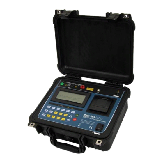
- Page 1 MD-5075x 5kV Insulation tester User’s Guide © 2009 Sourcetronic. All rights reserved.
-
Page 2: Used Symbols
Safety warnings • Before to use this instrument the User’s guide and Safety warnings must be read and understood. • Safety procedures and rules for working near high voltage energized systems must be observed during the use of this equipment. The generated voltages may be dangerous. -
Page 3: Table Of Contents
Index Used symbols _______________________________________________________ 4 1. Description _______________________________________________________ 6 2. Panel control functions ______________________________________________ 7 3. Keyboard ________________________________________________________ 8 4. Display __________________________________________________________ 9 5. Charging Battery _________________________________________________ 10 6. Connecting the MD-5075x __________________________________________ 10 7. Use of “Guard” (G) terminal _________________________________________ 12 8. -
Page 4: Description
1. Description The digital insulation tester model MD-5075x is at the cutting edge of SOURCETRONIC insulation analyzer equipment and it is one of the more complete and sophisticated of the international market. It uses an efficient well experienced technology, which provides safe, reliable and accurate measurements of insulation resistances up to 5TΩ... -
Page 5: Panel Control Functions
2. Panel control functions Voltage output terminal (-V) Zero reference terminal (+R) Guard (G) Terminal Display Keyboard High Voltage led On / Off key ... -
Page 6: Keyboard
3. Keyboard Function Α Turns the printer on/off Indicates that the printer is turned on. Β Hold – Freeze the last reading on the display The Hold function is on Χ Battery – exhibits the battery load status on Indicates that the battery the display charger is on ∆... -
Page 7: Display
Π Selection of 5kV test voltage Indicates 5kV selected Θ These keys (decrease or increase) enable – the selection of the value that is being Ρ programmed. Λ Activates/ enables programming of the limit Indicates when the for the “Pass / Fail” test measured resistance is lower than programmed limit... -
Page 8: Charging Battery
5. Charging Battery The MD-5075x uses a rechargeable Ni-MH 12V – 3Ah battery. This battery should be recycled at the end of its service life or placed in an appropriate site, in order to protect the environment. Charging Procedure: Test if the MD-5075x is off and connect it to the mains. The charging Χ... - Page 9 ELEMENT TO BE MEASURED RED TERMINAL BLACK BNC SAFETY CONNECTOR TERMINAL BLACK TERMINAL The terminals in the picture are merely illustrative, so there can be differences between them and the ones which really come with the equipment. Observation: At the time of the connection, the equipment automatically enters in the voltmeter mode and begins to exhibit both the circuit voltage and current in the display.
-
Page 10: Use Of "Guard" (G) Terminal
7. Use of “Guard” (G) terminal Depending on the measurement to be made, the Guard (G) may be used or not. During measurements, the equipment should be electrically grounded to avoid unsteady readings. When insulation is measured regarding grounding, the R terminal is connected to earth and the condition by means of which the equipment potential setting is fulfilled. -
Page 11: Test Voltage Definition
8.1. Test voltage definition In order to define the test voltage value, first it is necessary to select one of Ι ϑ Κ voltage adjustment keys: . These keys enable both the pre- Μ Ν Ο Π Θ Ρ programmed voltage selection ( ) and the keys which increase or decrease the value of the step voltage test for 25V, 100V... -
Page 12: Svt Mode (Step Voltage Tests)
8.2.3. SVT Mode (step voltage tests) Η The use of key allows the MD-5075x setting for the performance of a step voltage test; when this mode is selected, the display shows the SVT abbreviation. Under this operation mode, the user does not define a specific voltage test, but a maximum voltage value the device will start tests applying a 500V voltage and increase this value in 500V steps each minute until reaching the programmed voltage. -
Page 13: How To Perform Tests
9. How to perform tests Σ After having set the desired measurement, press key. The HIGH VOLTAGE indicator will turn on indicating that the megohmmeter is applying high voltage to the element under test. During some seconds the intelligent auto- range system will search for the most convenient range for the value under measure. -
Page 14: Measurement Of The Polarization Index (Pi)
9.1. Measurement of the Polarization Index (PI) Ε When pressing the key during the tests, the Polarization Index (PI) value will be exhibited on the display. It is only possible to apply this function after a minimum of 10 minutes of measurement; in case the key is pressed before this minimum limit, the display will show the message of value exhibition of PI value, but will not show any value. -
Page 15: Other Functions
10. Other functions 10.1.1. Backlight Φ The equipment display has a backlight. In order to activate it, press key. After 10 seconds the backlight will auto-turn off in order to economize the Φ battery charge. If you want to reactivate it, press key again. -
Page 16: Capacitance Measurement
10.1.5. Capacitance Measurement The capacitance value is obtained by measuring the insulation resistance. Γ After finishing measuring (When the Υ key has been pressed), press the key and the capacitance value will be exhibited on the display. Voltage Capacitance 500V 50nF up to 10µF 1.000V 50nF up to 5µF... -
Page 17: Auto Power-Off
10.1.8. Auto power-off The MD-5075x auto-turns off after 10 minutes of inactivity, or after 35 minutes of measuring without checking the battery status. 11. Data Transfer In order to transfer data from the MD-5075x to a computer, please use the cable provided with the accessories Connect it to the RS 232 port of the MD-5075x and the computer. -
Page 18: Megalogg2 Software
12. MegaLogg2 Software This software makes communication between MD-5075x and a computer with Windows operative system easier. It makes the transference of all the data recorded in the apparatus memory, enabling the user to synchronize the date and time of the equipment internal clock with the computer date and time, to generate graphics and reports of tests and to clear the memory of the megohmmeter. -
Page 19: Cleaning
14. Cleaning The panel, terminals and connectors of the equipment must stay dry and clean. Cleaning should be made using a wet cloth in water and a soft detergent or isopropyl alcohol (be sure that the products to be used for cleaning does not affect plastic goods). -
Page 20: Technical Specifications
15. Technical specifications Test voltages : 500 - 1,000 - 2,500 - 5,000V with fast selection. From 500V to 5kV selectable in 25V, 100V or 500V steps. DC, negative in relation to grounding. Maximum resistance reading : 5TΩ @ 5kV DC Voltmeter : 30V up to 600Vcc Precision: ±... - Page 21 Built-in chronometer : Indicates elapsed time from the beginning of the measurement mm: ss format, up to 90:00 Environmental protection : IP-54 (with closed lid) index Safety : Meets the requirements of IEC 61010-1/1990, IEC 61010 1/1992 amendment 2 Electromagnetic : In accordance with IEC 61326-1 compatibility (E.M.C) Electro magnetic irradiation...
-
Page 22: Application Note 32
16. Application note 32 Use of “Guard” terminal in megohmmeters When insulation resistance measurements are performed with megohmmeters, specially with high sensitivity instruments measuring high resistance values, the use of the GUARD terminal avoids the harmful influence of stray resistances. In order to better explain the function of this terminal, let us start reviewing the megohmmeter basic circuit diagram of Fig. - Page 23 If megohmmeter (terminals Vt and R) is connected to transformer terminals A and B, and considering that the resistance of the coils on each side of the transformer may be disregarded, Rx appears to be in parallel with (R1 + R2). The situation is changed if we connect the transformer housing to GUARD terminal.
-
Page 24: Warranty
This warranty is exclusive and is instead of all other warranties, express or implied, including but not limited to any implied warranty or merchantability or fitness for a particular purpose or use. SOURCETRONIC will not be responsible for any special, indirect, incidental, or consequential damages or loss of data, whether in contract, or otherwise.
Need help?
Do you have a question about the MD-5075 Series and is the answer not in the manual?
Questions and answers