
Related Manuals for Sourcetronic ST9110/A


Summary of Contents for Sourcetronic ST9110/A
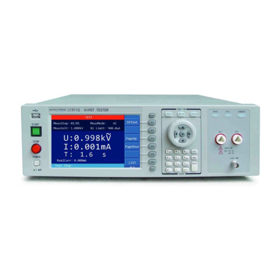
- Page 1 SOURCETRONIC − Quality electronics for service, lab and production User Manual AC/DC HiPot and IR Tester ST9110/A...
-
Page 2: Table Of Contents
Content Chapter 1 Overview ............................ 4 1.1 Introduction .................................4 1.2 Conditions of Use ..............................5 1.2.1 Power .................................... 5 1.2.2 Ambient Temperature and Humidity ............................5 1.2.3 Preheating ..................................5 1.2.4 Precautions ..................................5 1.3 Volume and Weight .............................6 1.4 Safety Requirements ............................6 1.4.1 Insulation Resistance ................................ - Page 3 4.6.2 Operation instruction ..............................37 4.7 File Storage................................ 39 4.8 HANDLER ................................ 40 4.8.1 Brief Introduction ................................40 4.8.2 External Control Line Legend ............................. 42 Chapter 5 Interface and Communication ....................45 5.1 Remote Control Interface ..........................45 5.1.1 RS232C Interface Instruction.............................. 45 5.1.2 GPIB Interface Instruction ..............................
-
Page 4: Chapter 1 Overview
Chapter 1 Overview Thank you for purchasing and using our device. Before using this device, please refer to the last chapter of “Warranty” in this manual to check and confirm, if there is any differences, please contact with us in order to protect your rights and interests. 1.1 Introduction ST9110/ST9110A AC/DC withstanding voltage &... -
Page 5: Conditions Of Use
to external equipment (such as a computer) or automatic test system conveniently. RS-232C interface: RS-232C provides convenient serial communication with the peripheral, the peripheral can conduct the set up of various functions and parameters of the tester through this interface. -
Page 6: Volume And Weight
filter. Do not use the tester in locations affected by strong magnetic or electric fields. Operation in a location subject to magnetic or electric fields may cause the tester to malfunction, resulting in electrical shock or fire. Do not use the tester in locations near a sensitive measuring instrument or receiver. Operation in a location subject, may cause such equipment may be affected by noise generated by the tester. -
Page 7: Electromagnetic Compatibility
1.5 Electromagnetic Compatibility Power Transient Sensitivity, refer to requirements of GB6833.4 Conductance Sensitivity, refer to requirements of GB6833.6 Radiative Interference, refer to requirements of GB6833.10 ◇7... -
Page 8: Chapter 2 Precautions On Handling
Chapter 2 Precautions on Handling This chapter describes the precautions to be followed in the handling of this tester. When using the tester, take utmost care to ensure safety. ! WARNING: The tester generates a 5kVAC or 6kVDC test high voltage, incorrect or wrong operation can cause accidents which will result in human injury or death. - Page 9 high voltage is remote controlled, so the operator can not know the actual working state of the tester through the interface. Please pay special attention to the reliability of remote control connection: [STOP] key must be connected reliably, and the [STOP] key must be pressed before changing the DUT.
-
Page 10: Handling Meansures
If the time constant of the DUT is known, then the time required to discharge to 30V can be calculated by the above formula after the output is cut off. 8) Turning ON or OFF the Power Switch Once the power switch is turned off, be sure to allow several seconds or more before turning it ON again, never turn on and off the power switch repeatedly, so as not to cause erroneous actions. - Page 11 Warning: Keep away from the instrument after turning off the power and prevent other people from approaching. Do not immediately disassemble the test circuit. Immediately call our distributor or agent. High voltage may remain in the interior of the instrument. It is hazardous for an unqualified person to attempt to troubleshoot any tester problem.
-
Page 12: Chapter 3 Panel Description
Chapter 3 Panel Description The contents of this chapter are only for a brief description. For details of operation and detailed explanation, refer to Chapter 4 for the corresponding content. 3.1 Front Panel Figure 3-1 gives a brief description of the front panel. Figure 3-1 1. -
Page 13: Rear Panel
setting interface; SYSTEM key: press the key and the corresponding key lights up, the system setting interface will be displayed; 9. Arrow keys, selection wheel Move the cursor on the screen by pressing the keys or turning the wheel, the selected parameter is displayed in blue. - Page 14 The high potential terminal of high voltage output, this is the high voltage output terminal, when DANGER light is on, it means there is high voltage delivering, touching is forbidden. 3. RTN/LOW Terminal High voltage test return/reference terminal, which is low potential terminal. 4.
-
Page 15: Chapter 4 Basic Operation
Chapter 4 Basic operation 4.1 Interface structure overview The following figure is the interface structure: TEST Start Test SETUP STEP:01/01 Insert Delete Save AC(AC WV) DC (DC WV) Parameters SYSTEM Test Parameters Environment Parameter FILE SAVE Communication Setup LOAD Figure 4-1 Operation Steps Interface Instructions: ... -
Page 16: System Setup
4.2 SYSTEM Setup 4.2.1 System Test Parameter Settings Operation Instructions: 1. Press the [SYSTEM] key to enter the system setting interface shown in Figure 4-2. 2. Press F1~F3 key to change the measurement, environment and interface related system settings. 3. Press [▲], [▼] key to move the cursor to the parameters you want to set. Change the parameter settings with F1~F5 keys or numeric keys. - Page 17 Setup items Range Default Explanation Manual Set the trigger mode of the instrument to start the Trg. Mode External Manual test, only accept the trigger signal in the current trigger mode. Set the delay time from the receipt of the trigger Trg.
- Page 18 signal in the current trigger mode and the trigger signal is only valid under the TEST interface. Before the completion of one measurement, the tester ignores other triggers. It can only be triggered again after the measurement is finished, or press the [STOP] key to exit the current measurement, and then trigger the measurement again.
- Page 19 Figure 4-3 4.2.1.4 Auto Range When the auto range, that is, the withstanding voltage auto range function is set to ON, at 0.6s before the completion of the test, if the measured current can be expressed by a lower current range, the current range is automatically changed to that lower current range.
- Page 20 3. Then at 0.6s before the completion of the test, the current range is switched to the appropriate lower range, which is 0.092mA in Figure 4-4.3. Figure 4-4.3 4.2.1.5 Electric Shock Protection (GFI) Note: The output power of this tester can reach 500VA and the output current reaches 100mA (AC withstanding voltage testing mode).
- Page 21 b) When the electric shock protection is set to FLOAT, the high-voltage output high terminal HV1 and low terminal HV2 are in a float state, as shown in Figure 4-6. When the human body accidentally touches the test high voltage terminal, as the low terminal HV2 of the high voltage circuit is not grounded, but isolated from the ground, equivalent to connecting a high insulation resistance, the current through the human body will not exceed 3 mA even if there are charged capacitors in the DUT, thus ensuring the safety of the operator, as shown in Figure 4-7.
-
Page 22: System Environment Parameters Setting
4.2.2 System Environment Parameters Setting Operation Instructions: 1. Press [SYSTEM] to enter the system setting interface shown in Figure 4-2. 2. Press [F2] key to enter the environment-related system settings shown in Figure 4-8. 3. Press [▲], [▼] to move the cursor to the parameter to be set. Change parameter settings via F1~F5 keys or numeric keys. -
Page 23: System Communication Setup
b) Press [F6], the key is locked; press [F6] again to unlock. There are corresponding icons and text prompts in the lower left corner of the page. 系 统 设 m F3 置 中 m F4 测 试 系 相 统... -
Page 24: Meas Setup
4.3 Meas SETUP Operation Instructions: 1. Press [SETUP] to enter the measurement setup interface shown in Figure 4-11. 2. INSERT, DELETE, NEW, SAVE or select up or down by pressing the F1~F6. 3. Press the right arrow key to move the cursor to the test mode option, as shown in Figure 4-12, uses the F1~F5 keys to select whether the test mode is AC withstand voltage, DC withstand voltage, insulation resistance, pause mode or open short circuit detection OSC. -
Page 25: Ac Withstanding Voltage Test Mode
4.3.1 AC Withstanding Voltage Test Mode 系 统 设 m F3 置 中 m F4 测 试 相 系 统 关 参 设 Figure 4-12 Meas Mode Setup 数 置 Setting Item Range Default Explanation 中 设 置 测 0.050~5.000kV, CLOSE Set the voltage required for AC MeasVolt... -
Page 26: Dc Withstanding Voltage Test Mode
The ramp time it takes to drop from the set voltage to low voltage. 0.1~999.0s, FallTime CLOSE CLOSE means that when the test time is 0 — CLOSE finished, the voltage output is cut off directly. Table 4-3 4.3.2 DC Withstanding Voltage Test Mode Figure 4-13 DC Withstanding Voltage Setup Setting item Range... - Page 27 When the RampJudg is set to ON, the DC withstanding voltage testing judges whether the current test value exceeds the set value of current high limit while performing the ramp time. RampJudg CLOSE or ON CLOSE When the RampJudg is set to Close, the DC withstand voltage testing does not judge whether the current test value exceeds the set value of current high limit while...
-
Page 28: Insulation Resistance Test Mode
4.3.3 Insulation Resistance Test Mode Figure 4-14 IR Test Setup Setting item Range Default Explanation Set the voltage required for the insulation 0.050~5.000kV, CLOSE MeasVolt resistance test. Must be changed from CLOSE to 0 —CLOSE (no test) a voltage for the step to become valid. 1.000MΩ... -
Page 29: Pause Mode
MeasRang: Select the appropriate current range for IR, calculate the current value according to the test voltage and the expected insulation impedance of the DUT, ie I = U/R, and then select the appropriate current range accordingly. Relationship between the current range and resistance measurement range is shown in table 4-6. -
Page 30: Osc Detection Mode Setup
4.3.5 OSC Detection Mode Setup Figure 4-16 OSC Detection Setup Set Up Range Default Explanations Set the conditions for judging the test 10%~100%, result as open, expressed as a percentage Open of the test value and the sampling standard Stepping 1% value. -
Page 31: Test Setup
系 统 设 m F3 置 中 m F4 测 试 相 系 关 统 参 设 Figure 4-17 Sampling Setup 数 置 设 4.4 TEST Setup 中 置 测 Operation Instructions: 如 试 1. Press [TEST] to enter the AC Test interface as shown in Figure 4-18.1. 图... - Page 32 系 统 设 m F3 置 中 m F4 测 试 相 系 关 统 参 设 Figure 4-18.1 AC Test Interface 数 置 设 中 置 测 如 试 系 图 相 统 关 设 所 参 m F3 置...
-
Page 33: 1Offset
系 统 设 m F3 置 中 m F4 测 试 相 系 关 统 参 设 Figure 4-18.4 OSC Test Interface 数 置 设 中 置 测 如 试 系 图 相 统 关 设 所 参 m F3 置... -
Page 34: Test Methods
系 统 设 置 中 m F4 测 试 系 相 统 关 设 参 Figure 4-19 STEP Display Interface 置 数 On the STEP display page, in addition to test steps, test mode information, there is also large font 中... -
Page 35: Sampling Operation Of Standard Capacitor
4.5.2 Sampling Operation of Standard Capacitor 1. Before Open Short-Circuit check mode (OSC) testing or testing a new capacitor DUT or replacing a capacitor DUT, the standard capacitance value must be sampled first, or manually input as the standard value. 2. - Page 36 [STOP] key is pressed. The test result in the lower right corner displays FAIL. Explanation Table for Fail: Displayed Test Result Meaning >High Limit Test value is greater than the set high limit. <Low Limit Test value is smaller than the set low limit. ARC FAIL Current arc exceeds high limit.
-
Page 37: Voltage Breakdown Test
effective capacitance value installed between the test terminals. Take a 3-coil inductor as an example: the capacitance between 1-2 is about 300P, 1-3 is about 200P, 2-3 may be short-circuited. First confirm the open circuit value, do not connect the DUT, sampling: Cs=100P;... - Page 38 系 统 设 m F3 置 中 m F4 测 试 相 系 关 统 参 设 数 置 Figure 4-22 设 中 置 测 如 试 图 系 相 统 关 所 设 参 m F3 示 置 数 中...
-
Page 39: File Storage
AC: 0~High Limit Value CLOSE Low Limit DC: 0~High Limit Value Set the low limit of leakage current. CLOSE 0—CLOSE AC: 0~20mA CLOSE Arc Limit DC: 0~10mA Set the high limit of Arc. CLOSE 0—CLOSE Set whether to continue the test when CONT ON/OFF all the setup steps are completed. -
Page 40: Handler
Function Explanation Create a new file. Save Save the currently loaded file. Load Load the file as the current file. Copy All Copy all files for batch processing. Copy Copy internal files to U disk, copy U disk files to internal. Delete Delete the current file. - Page 41 Interface Pin Description: Input/Out Pin# Signal Name Description /OPEN OSC OPEN output, used together with /PASS and /FAIL /SHORT OSC SHORT output, used together with /PASS and /FAIL The output is LOW when the test result is FAIL, at this time at /FAIL least one of /HIGH, /LOW, /ARC_FAIL, /GFI_FAIL and /SHORT_FAIL signal also will have output (LOW action).
-
Page 42: External Control Line Legend
4.8.2 External Control Line Legend Take the Internal Power Supply as an Example ◇42... - Page 43 Take the External Power Supply as an Example ◇43...
- Page 44 Timing Diagram Timing Diagram——Take 2 test steps as an example Time Range Explanations External trigger signal (/EXT_START) continuous active time, need at least >10mS about >10ms External trigger signal (/EXT_START) time needed from start until /EOT <20mS signal is cleared, <20ms ----------- Time setup for the trigger delay -----------...
-
Page 45: Chapter 5 Interface And Communication
Chapter 5 Interface and Communication The instrument can use RS232C serial interface (standard) or GPIB parallel interface (optional) for data communication and remote control without instrument panel, but they can not be used at the same time. They have the same programming commands but use different hardware configuration and telecommunication protocols. - Page 46 Signal Symbol Connector Pin# Transmit Data Receive Data Grounding This is the most easy and cost effective way to use serial ports communication. Note: The serial port pin definition of this tester is basically the same as the pin definition of the standard 9-core RS232C connector, only without the hardware handshake signals.
- Page 47 Press the SYSTEM menu button (F3 soft key) direction key to move the cursor to the port format RS232C soft key. Serial port main parameters Transfer Method Full-duplex asynchronous communication with start and stop bits Baud Rate 9600 bps/19200bps/38400bps/115200bps Data Bit 8 BIT or 7 BIT...
- Page 48 host should also read all loopback characters before reading the query result. 9) For some bus commands that take a long time to complete, such as offset, the host should actively wait for, or respond to the user's keyboard input confirmation to synchronize the execution of the previous command, to avoid the next command being ignored or errored during command execution.
- Page 49 { c = 0; for( m = 100;m;m-- ) { send_port( PORT,*ps ); for( n = 1000;n;n-- ) { delay( 2 ); /* wait about 2ms, use dos.h libray funtion */ if( kbhit() && ( getch() == 27 ) ) /* if escape key keypress */ { printf( "\nE20:Write Canceled!"...
- Page 50 /* send a character to serial port */ void send_port( int port,char c ) union REGS r; r.x.dx = port; /* serial port */ r.h.ah = 1; /* int14 function1:send character */ r.h.al = c; /* character to be sent */ int86( 0x14,&r,&r );...
-
Page 51: Gpib Interface Instruction
5.1.2 GPIB Interface Instruction 5.1.2.1 GPIB BUS The IEEE488 (GPIB) universal parallel bus interface is an internationally accepted intelligent instrument bus interface standard. IEEE is the English abbreviation of Institute of Electrical and Electronics Engineers, 488 is the standard number. Through this interface, it can communicate with a computer or other intelligent device, and can easily form an automatic test system together with other test instruments. - Page 52 GPIB Cable Connection Method #1: Tester Back Connector Figure5-2 Double Back Connector Staking GPIB Cable Connection Method #2: Figure 5-3 Four-Back Connector Stacking ◇52...
- Page 53 5.1.2.2 GPIB Interface Function This tester provides most of the general functions of GPIB except the controller, see the following table: Code Function Support all data source contact functions Support all digital panel meter contact functions Basic talk function; Talk only function; Talking cancelled when MLA; Do not support serial roll call Basic listen function;...
-
Page 54: Serial Port Commands Instruction
5.2 Serial Port Commands Instruction Brief Description of the Command Format: 1. The tester commands only describe the actual characters received or sent. 2. Command characters are all ASCII characters. 3. The data "<???>" of the command is an ASCII string. The default format of the system is integer or floating point number. -
Page 55: Function Subsystem Commands
--Example: Set the display page to measurement display. Command Syntax: DISP: PAGE TEST Query syntax: DISPlay:PAGE? Return format: TEST Set measurement page display mode: 0, step mode; 1, list mode Command Syntax: DISP:MODE 0 Query Syntax: DISP:MODE? Return Format: 0 5.2.3 FUNCtion Subsystem Commands 5.2.3.1 FUNCtion Subsystem Commands FUNCtion subsystem command is mainly used to set the test parameters of test function. - Page 56 Set the voltage for ACW test in STEP1 as 1000V. Command message: FUNC:SOUR:STEP 1:AC:VOLT 1000 Query message: FUNC:SOUR:STEP 1:AC:VOLT? Return value: 1000 FUNC:SOURce:STEP:AC:UPPC To set/inquiry about the UPPER current for ACW test. --Syntax: Command message: FUNC:SOUR:STEP <sn>:AC:UPPC<current> Query message: FUNC:SOUR:STEP <sn>:AC:UPPC? --Data<voltage>: Data format: float Data range: 0.001~120.000mA (voltage <4000V)
- Page 57 Query message: FUNC:SOUR:STEP <sn>:AC:TTIM? --Data<time>: Data format: float Data range: 0, 0.3~999.0s (0 is OFF) Data accuracy: 0.1s Data unit: s --Example: Set the TEST time for ACW test in STEP1 as 1s. Command message: FUNC:SOUR:STEP 1:AC:TTIM 1 Query message: FUNC:SOUR:STEP 1:AC:TTIM? Return message: 1.0 FUNC:SOURce:STEP:AC:RTIM To set /inquiry about the RISE time for ACW test.
- Page 58 Query message: FUNC:SOUR:STEP 1:AC:FTIM? Return message: 1.0 FUNC:SOURce:STEP:AC:ARC To set /inquiry about the ARC upper current for ACW test. --Syntax: Command message: FUNC:SOUR:STEP <sn>:AC:ARC<current> Query message: FUNC:SOUR:STEP <sn>:AC:ARC? --Data<current>: Data format: float Data range: 0, 1.0~20.0mA (0 is OFF) Data accuracy: 0.1mA Data unit: mA --Example: Set the ARC upper current for ACW test in STEP1 as 1mA.
- Page 59 Data range: 1~50 Data accuracy: 1 --Data<voltage>: Data format: float Data range: 50~6000 Data accuracy: 1 Data unit: V --Example: Set the voltage for DCW test in STEP1 to 1000V Command message: FUNC:SOUR:STEP 1:DC:VOLT 1000 Query message: FUNC:SOUR:STEP 1:DC:VOLT? Return value: 1000 FUNC:SOURce:STEP:DC:UPPC To set /inquiry about the UPPER current for DCW test.
- Page 60 FUNC:SOURce:STEP:DC:TTIM To set /inquiry about the TEST time for DCW test. --Syntax: Command message: FUNC:SOUR:STEP <sn>:DC:TTIM<time> Query message: FUNC:SOUR:STEP <sn>:DC:TTIM?--Data<time>: --Data format: float Data range: 0, 0.3~999.0s (0 is OFF) Data accuracy: 0.1s Data unit: s --Example: Set the test time for DCW test in STEP1 to 1s Command message: FUNC:SOUR:STEP 1:DC:TTIM 1 Query message: FUNC:SOUR:STEP 1:DC:TTIM? Return value: 1.0...
- Page 61 FUNC:SOURce:STEP:DC:WTIM To set /inquiry about the wait time for DCW test. --Syntax: Command message: FUNC:SOUR:STEP <sn>:DC:WTIM<time> Query message: FUNC:SOUR:STEP <sn>:DC:WTIM? --Data<time>: Data format: float Data range: 0~999.0s (0 is OFF) Data accuracy: 0.1s Data unit: s --Example: Set the wait time for DCW test in STEP1 as 1s. Command message: FUNC:SOUR:STEP 1:DC:WTIM 1 Query message: FUNC:SOUR:STEP 1:DC:WTIM? Return message: 1.0...
- Page 62 Set the RAMP arc for DCW test in STEP1 to 1mA. Command message: FUNC:SOUR:STEP 1:DC:RAMPARC 1 Query message: FUNC:SOUR:STEP 1:DC:RAMPARC? Return message: 1.0 FUNC:SOURce:STEP:DC:RAMPARC To set /inquiry about the RAMP state for DCW test. --Syntax: Command message: FUNC:SOUR:STEP <sn>:DC:RAMP<ON/OFF>or<1/0> Query message: FUNC:SOUR:STEP <sn>:DC:RAMP? --Data<voltage>: Data format: character...
- Page 63 Data accuracy: 1.0 MΩ Data unit: MΩ --Example: Set the upper resistance for IR test in STEP1 to 1 MΩ. Command message: FUNC:SOUR:STEP 1:IR:UPPR 1 Query message: FUNC:SOUR:STEP 1:IR:UPPR? Return value: 1 FUNC:SOURce:STEP:IR:LOWR To set /inquiry about the LOWER resistance for IR test. --Syntax: Command message: FUNC:SOUR:STEP <sn>:IR:LOWR<resistance >...
- Page 64 Data range: 0~999.0s (0 is OFF) Data accuracy: 0.1s Data unit: s --Example: Set the rise time for IR test in STEP1 to 1s. Command message: FUNC:SOUR:STEP 1:IR:RTIM 1 Query message: FUNC:SOUR:STEP 1:IR:RTIM? Return value: FUNC:SOURce:STEP:IR:FTIM To set /inquiry about the FALL time for IR test. --Syntax: Command message: FUNC:SOUR:STEP <sn>:IR:FTIM<time>...
- Page 65 Data format: characters --Example: Set the PA message in STEP1 to HELLO! Command message: FUNC:SOUR:STEP 1:PA:MESSAge HELLO! Query message: FUNC:SOUR:STEP 1:PA:MESSAge? Return value: HELLO! FUNC:SOURce:STEP:PA:TIME To set /inquiry about the PA state continue time. –Syntax: Command message: FUNC:SOUR:STEP <sn>:PA:TIME<time> Query message: FUNC:SOUR:STEP <sn>:PA:TIME? --Data<time>: Data format: float Data range: 0, 0.3~999.0s...
- Page 66 Query message: FUNC:SOUR:STEP <sn>:OS:SHOT? --Data< rate>: Data format: integer Data range: 0, 100~500 (0 is OFF) Data accuracy: 10 Data unit: --Example: Set the SHOT rate for OS test in STEP1 as 100%. Command message: FUNC:SOUR:STEP 1:OS:SHOT 100 Query message: FUNC:SOUR:STEP 1:OS:SHOT? Return value: FUNC:SOURce:STEP:OS:GET Outputs the capacitance.
- Page 67 Data format: integer Data range: 0 ~ 1 (0: normal step; 1: voltage step) --Example: Set the step mode for breakdown test to 1 (voltage step). Command message: FUNC:BREAK:STEPMODE 1 Query message: FUNC:BREAK: STEPMODE? Return value: FUNC:BREAKdown:STEP To set /inquiry about the STEP for voltage breakdown test. --Syntax: Command message: FUNC:BREAK:STEP<step>...
- Page 68 Data range: 0 ~ 1 (0: AC; 1: DC) --Example: Set the mode for breakdown test: 1 (DC) Command message: FUNC:BREAK:MODE 1 Query message: FUNC:BREAK: MODE? Return value: FUNC:BREAKdown:VOLTStart To set /inquiry about the VOLTAGE START for voltage breakdown test. --Syntax: Command message: FUNC:BREAK:VOLTS<voltage >...
- Page 69 --Data<current>: Data format: float Data range: 0.0001~25mA (DC); 0.001~100mA (AC) Data accuracy: 0.0001mA (DC); 0.001mA (AC) Data unit: mA --Example: Set the upper current for breakdown test to10mA. Command message: FUNC:BREAK:UPPC 10 Query message: FUNC:BREAK:UPPC? Return value: 10.000 FUNC: BREAKdown:LOWC To set /inquiry about the LOW CURRENT for voltage breakdown test.
- Page 70 --Syntax: Command message: FUNC:BREAK:RTIM<time> Query message: FUNC:BREAK:RTIM? --Data<time>: Data format: float Data range: 0~999.0s (0 is OFF) Data accuracy: 0.1s Data unit: s --Example: Set the rise time for breakdown test to1s. Command message: FUNC:BREAK:RTIM 1 Query message: FUNC:BREAK:RTIM? Return value: FUNC: BREAKdown:WTIM To set /inquiry about the WAIT TIME for voltage breakdown test.
-
Page 71: System Subsystem Commands
FUNC:BREAKdown:CONTinue To set /inquiry about the CONTINUE ON OFF for voltage breakdown test. --Syntax: Command message: FUNC:BREAK:CONT<ON OFF> Query message: FUNC: :BREAK: CONT? --Data<ON OFF>: Data format: integer Data range: 0, 1 (0: OFF; 1: ON) --Example: Set the continue test on off for breakdown test to 1(ON). Command message: FUNC:BREAK: CONT 1 Query message: FUNC:BREAK: CONT? Return value: 1... - Page 72 Data accuracy: 0.1s Data unit: s --Example: Set the trigger delay to 1.0s. Command message: SYSTem:MEA:TRGDLY 1.0 Query message: SYSTem:MEA:TRGDLY ? Return value: 1.0 SYSTem:MEA:MEAMODE To set /inquiry about the MEASURE MODE for test. --Syntax: Command message: SYSTem:MEA:MEAMODE<mode> Query message: SYSTem:MEA:MEAMODE ? --Data<mode>: Data format: characters Data range: 0~2 (0:normal, 1:repeat, 2:cycle)
- Page 73 --Example: Set the test interval to 1.0s. Command message: SYSTem:MEA:RPTINT 1.0 Query message: SYSTem:MEA:RPTINT ? Return value: 1.0 SYSTem:MEA:AFTERFAIL To set /inquiry about the AFTER FAIL status. --Syntax: Command message: SYSTem:MEA:AFTERFAIL<status > Query message: SYSTem:MEA:AFTERFAIL ? --Data<mode>: Data format: characters Data range: 0~2 (0:continue, 1:repeat, 2:stop) --Example: Set the after fail status to continue.
- Page 74 Set the step hold interval to 1.0s. Command message: SYSTem:MEA:STEPHOLD 1.0 Query message: SYSTem:MEA:STEPHOLD ? Return value: 1.0 SYSTem:MEA:HARDAGC To set /inquiry about HARDWARE COMPENSATION status. --Syntax: Command message: SYSTem:MEA:HARDAGC <ON/OFF>or<1/0> Query message: SYSTem:MEA:HARDAGC? --Data<ON/OFF>: Data format: characters Data range: OFF(0),ON (1) --Example: Set the hardware compensation to ON.
- Page 75 --Syntax: Command message: SYSTem:MEA:GFI <ON/OFF/FLOAT>or<1/0/2> Query message: SYSTem:MEA:GFI? --Data<ON/OFF/FLOAT>: Data format: characters Data range: OFF (0), ON (1), FLOAT (2) --Example: Set GFI to 1. Command message: SYSTem:MEA:GFI 1 Query message: SYSTem:MEA:GFI? Return value: 5.2.4.2 Commands for ENV Setup Function SYSTem:ENV:KEYVOL To set /inquiry about the state for KEY VOLUME.
- Page 76 --Data<ON/OFF>: Dataformat: characters Data range: OFF (0), ON (1) --Example: Set the pass volume to ON. Command message: SYSTem:ENV:PASSVOL 1 Query message: SYSTem:ENV:PASSVOL? Return value: 1 SYSTem:ENV:FAILVOL To set /inquiry about the state for FAIL VOLUME. --Syntax: Command message: SYSTem:ENV:FAILVOL <ON/OFF>or<1/0> Query messa: SYSTem:ENV:FAILVOL? --Data<ON/OFF>: Data format: characters...
- Page 77 Command message: SYSTem:ENV:KEYLOCK 0 Query message: SYSTem:ENV:KEYLOCK? Return value: 0 SYSTem:ENV:KEYLOCK:UNLOCK To set /inquiry about the state for UNLOCK. --Example: Release the button lock status under the bus unlock setting condition Command message: SYSTem:ENV:KEYLOCK:UNLOCK SYSTem:ENV:BRIght To set /inquiry about the state for backlight BRIGHT. --Syntax: Command message: SYSTem:ENV:BRIght <brightness>...
-
Page 78: Mmem Subsystem Commands
Command message: SYSTem:ENV:TIME 16 23 23 Query message: SYSTem:ENV:TIME? Return value: 16, 23, 23 5.2.5 MMEM Subsystem Commands MMEM:SAVE SAVE the current settings to a file stored internally as <filename>. --Syntax: Command messag: MMEM:SAVE <file name> --Data<file name>: Data format: characters Return value: OK --Example: Set save file name: ST9110TEST... -
Page 79: Usb Subsystem Commands
5.2.6 USB Subsystem Commands USB:SAVE SAVE current settings to external storage file name. --Syntax: Command message: USB:SAVE <file name> --Data<file name>: Data format: characters Return value: OK --Example: Set the save file name to ST9110TEST. Command message: USB:SAVE ST9110TEST USB:LOAD LOAD current settings to external storage file name. -
Page 80: Other Commands
*IDN Inquiry about the model and version information of the instrument. Return message: <manufacturer>,<model>,<firmware><NL^END> Where, <manufacturer> Gets the manufacturer name (Sourcetronic) <model> Gets the machine model (such as ST9110/9110A) <firmware> Gets the version number of firmware (such as Version1.0.5) For example: *IDN? -
Page 81: Chapter 6 Technical Parameter
Chapter 6 Technical Data Model ST9110 ST9110A Withstanding Voltage Test Range 0.05-5.0kV Waveform 50/60Hz ±0.1% Sinusoidal Wave Output 500VA (5.0kV 100mA) Output Voltage Power Range 0.05-6.0kV Output 150VA (6.0kV 25mA) Power Load Regulation ± (1%set value + 0.2%full scale) (rated power) Voltage Resolution Voltage Accuracy ±... - Page 82 OSC Detection Sampling Standard Capacitance Range 0.001~40nF Open Circuit Judgement Range 10%~100% Short Circuit Judgement Range 100%~500% Time Setting Test Time 0.3~999s, 0 indicates continuous testing Rise Time 0.1~999s, 0 is OFF Fall Time 0.1~999s, 0 is OFF Wait Time 0.1~999s, 0 is OFF (on DC withstanding voltage) Safety Protection Function ————————...
-
Page 83: Chapter 7 Warranty
Chapter 7 Warranty Warranty period: the warranty period is one year calculated from the date of shipment from our company. The warranty card should be issued for the warranty service. During the warranty period, if the buyer damages the tester due to improper operation, the maintenance cost shall be borne by the buyer. - Page 84 SOURCETRONIC GMBH Fahrenheitstrasse 1 28359 Bremen Germany T +49 421 2 77 99 99 F +49 421 2 77 99 98 info@sourcetronic.com www.sourcetronic.com skype: sourcetronic www.sourcetronic.com...
Need help?
Do you have a question about the ST9110/A and is the answer not in the manual?
Questions and answers