
Related Manuals for Sourcetronic ST2826


Summary of Contents for Sourcetronic ST2826
- Page 1 ST2826/A High Frequency LCR Meter SOURCETRONIC GMBH Email: info@sourcetronic.com Website:http:// www.sourcetronic.com...
-
Page 3: Table Of Contents
ST2826 Operation manual Ver1.0 CONTENT CHAPTER 1 THE INTRODUCTION AND INSTALLATION ..........1 1.1 I ........................1 NTRODUCTION 1.2 I .......................... 1 NSPECTION 1.3 P ......................1 OWER CONNECTION 1.4 F ............................. 2 1.5 E ........................2 NVIRONMENT 1.6 T .................... - Page 4 ST2826 Operation manual Ver1.0 3.3.1Parameter ........................18 3.3.2Nominal ........................18 3.3.3Bin ..........................18 3.3.4High and low limit ....................... 18 3.3.5Count ........................... 18 3.3.6 (AUX) ......................... 19 3.3.7(OUT) .......................... 19 3.3.8File management ......................19 3.3.9Auxdiary tools ......................19 3.4 <L >...
- Page 5 ST2826 Operation manual Ver1.0 3.6.3 Nomianl value setting ....................34 3.6.4 Compare function ON/OFF ..................34 3.6.5 Aux bin ON/OFF ..................... 34 3.6.6 High and low limit ....................34 3.6.7 File management ...................... 35 3.6.8 Auxdiary tool ......................35 <L >...
- Page 6 ST2826 Operation manual Ver1.0 4.2.1Introduction of save/load function ................45 4.2.2Folder /structure in U disk ................... 45 4.2.3(*.STA) ........................46 4.2.4 Operational step of file management ............... 48 4.3 <N > ....................48 ETWORK SETTING PAGE 4.3.1Network card status ..................... 49 4.3.2Host name ........................
- Page 7 7.2.2GPIB address ....................... 83 7.2.3 GPIB Bus Fucntion ..................... 83 7.2.4(SCPI) ........................83 7.3 LANR ..................84 EMOTE CONTROL SYSTEM 7.3.1 visit ST2826 by browser ..................... 85 7.3.2 Visit ST2826 by labview ..................... 85 7.4USB R ..................85 EMOTE CONTROL SYSTEM...
- Page 8 7.5USBCDCV ..................... 86 IRTUAL PORT 7.5.1 system configuration ....................86 7.5.2 Install drive ......................... 86 CHAPTER 8 ST2826 COMMANDS ..................87 8.1S ST2826 ................87 UBSYSTEM COMMANDS FOR 8.1.1 DISPlay subsystem command set ................87 8.1.2FREQuency subsystem command set ................89 8.1.3VOLTage subsystem command set ................
- Page 9 ST2826 Operation manual Ver1.0 : : : The description in the manual doesn‘t mean all contents in instrument. Sourcetronic reserves the rights to change the performance, function, inner structure, appearance, accessory and package without any inform!
-
Page 11: Chapter 1 The Introduction And Installation
Introduction ST2826 series component tester is the new generation impedance tester which meets the LXI standard,it can fit all test requirement of component and material with its 0.1% basic accuracy and 20Hz ~ 5MHz frequency. It can test low ESR capacitor and high Q inductor and also be applied in analyze of the electrical performance in microphone, oscillator, inductor, ceramic capacitor, LCD, variode, transformer.etc. -
Page 12: Fuse
ST2826 Operation manual Ver1.0 Fuse The fuse is available, be sure to use our own fuse. —————————————————————————————————— Warning:The position of fuse should fit the feed voltage range. —————————————————————————————————— Environment (1)Please do not operate the instrument in the place that is vibrative, dusty, under direct sunlight, or where there is corrosive air. -
Page 13: Chapter 2 Panel And Operation
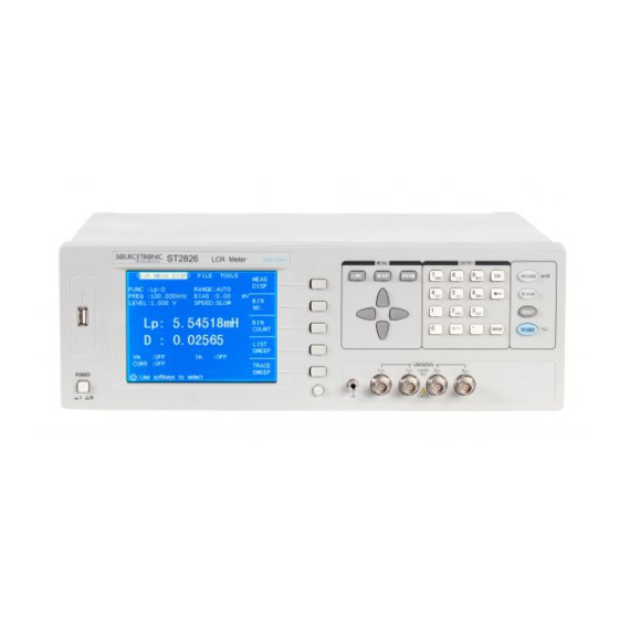
ST2826 Operation manual Ver1.0 Chapter 2 Panel and operation In this chapter, it introduces the basic operational feature of ST2826 series. Before using ST2826 series,please read this chapter to help you learn how to operate ST2826. 2.1 Front panel In figure 2-1 the front panel of ST2826 is introduced briefly. - Page 14 ST2826 Operation manual Ver1.0 Ground The terminal is connected with the case of instrument which can be used to protect and shield the ground terminal. UNKNOWN Four terminal pair test terminal which is used to connect four terminal pair fixture or cable.
-
Page 15: Rear Panel
[ENTER] [ENTER] is used to stop data being input,confirm and save the data displayed in inputting line(the bottom line in LCD). 2.2Rear panel In figure 2-2 the rear panel of ST2826 is introduced briefly。 DC BIAS INTERFACE IEEE-488 RATING FUSE... -
Page 16: Definition Of Displayed Zone
Warning:The position of fuse should fit the feed voltage range. —————————————————————————————————— (11)Ground The terminal is connected with case of instrument for protecting or shielding ground connection. 2.3Definition of displayed zone ST2826 adopts 320×240 LCD, and the displayed content is divided as the following zones, in figure 2-3. ◇6... - Page 17 ST2826 Operation manual Ver1.0 Figure 2-3 Display zone Indicates the name of page. File zone Move cursor to this zone to operate file management, which includes:load, save and delete. Tools zone Where some uncommon functions are listed,not displaying in corresponding zone.
-
Page 18: Main Menu And Corresponding Displayed Page
For entering system setting page, about the start key of system setting and file list function, the function pare includes: System setting 2.5Basic operation The basic of ST2826 is listed as below: Use([LCRZ],[SETUP],[SYSTEM])and softkey to select the displayed page you need. (In figure 2-5)... - Page 19 ST2826 Operation manual Ver1.0 instrument is set up, and the open picture is displayed. If user sets the password protection,then inputting password is required,input the password according to the note in screen,press [ENTER] to enter main menu. —————————————————————————————————— : : in this series, the password is set ,...
-
Page 20: Chapter 3[Lcrz]
ST2826 Operation manual Ver1.0 Chapter 3[LCRZ] 3.1 <LCRZ> page After pressing [LCRZ],<LCRZ> will be displayed on the screen. As figure 3-1: Figure 3-1 On the page above,the test result is displayed by large character. The following parameters can be set on this page. -
Page 21: 1Measure
ST2826 Operation manual Ver1.0 3.1.1Measure In ST2826, two parameters of impedance component can be tested meanwhile:Primary parameter and secondary parameter. The parameter is as below: Primary parameter (Module of impedance) (Module of admittance) (Inductance) (Capacitance) (Resistance) ... -
Page 22: 2Range
The range can be selected according to the impedance value of LCR component. ST2826 has 10 AC ranges:1Ω, 10Ω, 30Ω, 100Ω, 300Ω, 1kΩ, 3kΩ, 10kΩ、100kΩ and 1MΩ. ST2826 has 10 DCR ranges: 1Ω, 10Ω, 30Ω,100Ω, 300Ω, 1kΩ, 3kΩ, 10kΩ,、100kΩ and 1 MΩ. -
Page 23: 3Frequency
(Hz, kHz, and MHz), which can be used to input unit and data. When using [ENTER] to input frequency,the default unit is Hz. 3.1.4Test level The test level of ST2826 is set as the valid value of sine wave. The frequency of sine signal is ◇13... -
Page 24: 5Dc Bias
There are 4 kinds if signal source input impedance in ST2826. When test function is selected as DCR,Frequency zone displays―----‖. : : In ST2826, the current is the output current value when the tested terminal is shorted. :... -
Page 25: 6Speed
Refer to 4.2<File management>. 3.1.8Other tools In ST2826, the test result is displayed with 5 digits of floating point. The arithmetic point lock function can make ST2826 output result by means of fixed point position. This function is used to change the displayed digit of test result. -
Page 26: Bin No.display> Page
ST2826 Operation manual Ver1.0 Arithmetic point lock B Press Arithmetic point lock A to lock the position of arithmetic point in primary parameter result. When the arithmetic point is locked,―▲‖ is displayed. Press Arithmetic point lock A once,the last digit will be deleted, and the displayed digit will be reduced by one. -
Page 27: 1Comparator Function
3.2.1Comparator function The internal compare function of ST2826 can be divided into 10 bins at most(BIN1 to BIN9 and BIN OUT) . 9 pairs of primary parameter limit and a pair of secondary bin limit can be set. If the primary parameter of DUT is within the bin limit range, but its secondary one is not, then the DUT is sorted to subsidiary bin. -
Page 28: 1Parameter
ST2826 Operation manual Ver1.0 Figure 3-3 The following parameters can be set on <Bin count display> File management(File) Other tools(Tool) There are 3 zones,which are :Bin No. count display,File and Tool. Each function will be introduced below. The test result/condition zone displays the information below. The monitor zone can‘t be set on this page, but can be set on <Limit list setting>... -
Page 29: Aux)
Press NO,cancel the reset operation. 3.4 <List sweep display> page In ST2826 Max.10 points of frequency, level or DC bias can be output on <List sweep setting> page. Each list sweep test point can be set high and low value, which will be tested automatically;... -
Page 30: Sweep Mode
In ST2826, Max. 10 points of frequency, level or DC bias can be tested automatically. There are two types of list sweep mode in ST2826: SEQ and STEP. In SEQ mode, press [TRIGGER] once,all list sweep points are tested for once. In STEP,press [TRIGGER] once, only test a sweep point. -
Page 31: Frequency(Hz)
ST2826 Operation manual Ver1.0 displayed. STEP Press SEQ,select SEQ mode. Press STEP, select STEP mode. 3.4.2 Frequency(Hz) The current parameter mode and unit are displayed. The parameter item of sweep list is 其正 displayed. 3.4.3 Cp[F] D[ ] The ―function‖... -
Page 32: Trigger Mode
EXT(external trigger) and BUS(bus trigger). When the trigger mode is set as INT mode,ST2826 can test constantly. When the trigger mode is set as MAN mode, press [TRIGGER] once,ST2826 performs a test. When the trigger mode is set as EXT mode, once HANDLER receives a trigger signal of positive pulse,ST2826 performs a test. -
Page 33: Auto Level Control Function
ST2826 Operation manual Ver1.0 performs a test. BUS trigger mode can‘t be set on the front panel. : : when ST2826 is in the process of test , : a trigger signal is received, it will be ignored. ST2826 send trigger signal after test ends. -
Page 34: Average Time
ST2826 Operation manual Ver1.0 3.4.10 Average time The average function of ST2826 can calculate the result of 2 tests or more in average. The setting range is from 1 to 255 with the stepper of 1. Operational step of average setting Set average time according to the operation below. -
Page 35: Signal Source Internal Resistance
3.4.13 Signal source internal resistance ST2826 provides 4 kinds of signal source internal mode:30 Ω、100 Ω、10 Ω/CC(Constant Current) and 50 Ω. When the inductance is tested, in order to compare the data of other tester, the signal source internal mode should be same. -
Page 36: File Management
Measure When the component is connected to the test terminal,press Measure. ST2826 tests the component, and the result is output automatically to be the value of reference A andB. Use softkeyMeasure or numeric key to input the reference value of primary parameter. -
Page 37: Auxdiary Tools
On <Measure>, the tools provides the function of system reset and clear setting. The system reset can restart ST2826. The operational step Execute the operation to reset ST2826 and load the setting parameter on <Measure> . Move cursor to Tool zone,the following softkeys are displayed. System reset ... -
Page 38: Open Correction
[kHz] [kHz] [kHz] [MHz] ST2826 can set 3 open correction frequency point: Freq 1, Freq 2 and Freq 3. Move cursor to Freq 1,Freq 2 or Freq 3 ,use open single clear to correct 3 set frequency. Operational step of open correction Move cursor to Open,the following softkeys are displayed. -
Page 39: Short Correction
Short full clear to execute the short correction. The 41 fixed frequency points is the same as open correction. ST2826 can set 3 open correction frequency points: Freq 1, Freq 2 or Freq 3 Move cursor to Freq 1,Freq 2 or Freq 3. Use Short single clear to correct 3 set frequency. -
Page 40: Load Correction
The softkey can cancel the current open correction. The former data is reserved. Press DCR open,ST2826 can test short resistance Press ON, the short correction is valid, ST2826 then perform short correction calculation . If frequency1,frequency 2 and frequency 3 is set as OFF, the insertation method is adopted to calculate the date. -
Page 41: Load Correction Test Function
ST2826 Operation manual Ver1.0 Press Open single clear to open correct the set frequency. Move cursor to Open. Press ON. Move cursor to Freq 1,Freq 2 or Freq 3. 10) Use fixture to short. 11) Press Short single clear to short correct the set frequency. -
Page 42: Swop Parameter
As figure 3-9: Figure 3-9 ST2826 can set bin limit of 9 primary parameters and bin limit value of a secondary parameter. The test result can be sorted into 10 bins at most(BIN1 to BIN9 and BIN OUT). If the primary parameter is within BIN1 to BIN9,... -
Page 43: Compare Function Limit Mode
ST2826 Operation manual Ver1.0 former setting. 3.6.2 Compare function limit mode Compare function provides two modes. As figure 3-10. Tolerance mode Set the tolerance value of nominal value as compare limit value. There are two modes:one is percentage tolerance and the other is absolute value one. -
Page 44: Nomianl Value Setting
3.6.4 Compare function ON/OFF ST2826 can set bin limit of 9 primary parameter and bin limit value of a secondary parameter. The test result is sorted to 10 bins at most(BIN1 to BIN9 and BIN OUT). Operational step of setting compare function ON/OFF Move cursor to Comp. -
Page 45: File Management
ST2826 Operation manual Ver1.0 Operational step of setting high and low limit Set Param,Nomi and Mode. Move cursor to Tool. Move cursor to Low limit of Bin 1. if you select tolerance mode, execute step 4 to step 7; if you select sequentional mode, execute step8 to 12. -
Page 46: Mode
ST2826 Operation manual Ver1.0 Figure 3-11 ST2826 can test 10 frequency,level or bias voltage. The following sweep parameters can be set on <List sweep setting>. (Mode) ( [Hz], level [V], level [I], bias [V], bias [I]) (sweep point) ... -
Page 47: Trace Sweep Setting
ST2826 Operation manual Ver1.0 3.8 <Trace sweep setting> Press [SETUP],Measure,Correction,Limit setting,List setting and Trace setting are displayed. Press Curve setting. The following page is displayed. As figure 3-12: Figure 3-12 3.8.1 Mode ―Mode‖ includes [Hz], level [V], level [A], bias [V], bias [A]. -
Page 48: Trace Sweep Display
ST2826 Operation manual Ver1.0 3.9 <Trace sweep display> Press [LCRZ],Measure,Correction,Limit setting,List setting and Trace setting are displayed Press Trace sweep. The following page is displayed. Figure 3-13 Press 【TRIGGER】to start sweeping. 3.9.1 A max and A)value 3.9.2 A min and a)value 3.9.3... - Page 49 ST2826 Operation manual Ver1.0 of curve for each sweep; Lock PressRatio:Lock,it displays Ratio:Auto,now system locks the display ratio of curve. 3) Load Press Load ,it displays Load ,which means load data status. Now the following figure is displayed: :...
- Page 50 ST2826 Operation manual Ver1.0 sweep,when user presses [TRIGGER] once,then the instrument sweeps curve. PressTrigger: MAN, the zone displaysTrigger: EXT, which means external trigger sweep,when the external interface or computer triggers once, then instrument sweeps curve. Press Trigger:EXT,the zone displaysTrigger:INT,which means internal trigger sweep,after instrument sweeps curve, it performs next time automatically.
- Page 51 ST2826 Operation manual Ver1.0 Figure 3-15 ◇41...
-
Page 52: Chapter 4 [System] Menu And File
ST2826 Operation manual Ver1.0 Chapter 4 [SYSTEM] menu and file 4.1<System> Press [SYSTEM],then [System setting] to enter <System setting> page. Shown as figure 4-1: Figure 4-1 This page includes LCR contrast, beeper, alarm, language, password, bus mode, bus address .etc. -
Page 53: 4Fail Beeper
ST2826 Operation manual Ver1.0 HIGH LONG HIGH SHORT LOW LONG TWO SHORT 4.1.4Fail beeper The zone is used to control and display the test result as beeper mode when interior products are tested. Operational step of setting fail beeper:... -
Page 54: 8Bus Address
ST2826 Operation manual Ver1.0 RS232C GPIB USBTMC USBCDC Press RS232C to select RS232C interface bus. Press GPIB to select GPIB bus. Press LAN to select LAN bus. Press USBTMC to select USBTMC bus. Press USBCDCto select USBCDC bus. -
Page 55: File Management Page
Include the test result such as *.CSV file. Include configuration information, such as *.STA file. Include the serene picture as *.BMP file. Note : The folder of CSV,STA and BMP can be valid when U disk is connected to ST2826. ◇45... -
Page 56: Sta
ST2826 Operation manual Ver1.0 The folder and file structure in U disk is shown as Figure 4-2: E:(U disk) \STA 2826001.STA 2826002.STA 2826003.STA 2826999.STA \CSV 2826001.CSV 2826002.CSV 2826003.CSV 2826999.CSV \BMP 2826001.BMP 2826002.BMP 2826003.BMP 2826020.BMP …… Figure 4-2 4.2.3(*.STA) The instrument can save 20 groups of *.STA file. - Page 57 ST2826 Operation manual Ver1.0 The set parameter on <Limit list> page Function(Swap parameter) Nominal value(Reference value) Compare mode(%-TOL/ABS-TOL/SEQ-MODE) Aux Bin (ON/OFF) Compare function (ON/OFF) High and low limit value of each bin The set parameter on <List sweep > page ...
-
Page 58: Operational Step Of File Management
ST2826 Operation manual Ver1.0 4.2.4 Operational step of file management A. Check the existed file Press File manage to enter <File management > page. User can switch in ―I:(Internal file list)‖ and ―E:(External file list)‖by[←] [→]. Use [↑] [↓] to check one by one. -
Page 59: 1Network Card Status
DHCP is the abbreviation of Dynamic Host Configuration Protocol. Operation of setting DHCP: Move cursor toDHCP. The following softkeys are displayed. Turn on DHCP Note:there must be a DHCP server in LAN,ST2826 can obtain a correct net parameter. Don‘t use DHCP. 4.3.4Auto IP When DHCP is available,select auto IP,ST2826 can obtain a correct net parameter. -
Page 60: Ip Add
ST2826 Operation manual Ver1.0 Use static IP. 4.3.5 IP Add Operation of setting IP address: (1)Move cursor to IP add. Move cursor to where the IP address is modified. (2)The following softkeys are displayed. ↑(+) Increase the value of IP address. - Page 61 ST2826 Operation manual Ver1.0 ◇51...
-
Page 62: Chapter 5 Measurement Procedure And Examples
ST2826 Operation manual Ver1.0 Chapter 5 Measurement procedure and examples This chapter covers basic measurement procedures and examples. It also offers various measurement hints. 5.1Clear (CORRECTION OPERATION) To prevent the stray capacitance from disturbing the measurement accuracy, you must do the OPEN/SHORT CORRECTION. -
Page 63: Dot Frequency Clear (For Single Frequency)
ST2826 Operation manual Ver1.0 Press OFF, close the dot frequency clear function for frequency 2. Move the cursor to FREQ 3 field. ON, OFF, MEAS OPEN, MEAS SHORT and MEAS LOAD will be displayed in the softkey area. Press OFF, close the dot frequency clear function for frequency 3. -
Page 64: The Right Connection Between The Test Fixture And The Dut
If you do the test with high accuracy, to use the test fixture is recommended. No matter you use the test fixture provided by Sourcetronic Company, Kelvin test leads or the test fixture made by yourself, the following requirement must be met: 1) The distributed resistance must be decreased to the minimum, especially when the high resistance DUT is tested. - Page 65 ST2826 Operation manual Ver1.0 Shielded ground Test terminal Metal conductor Figure 5-1 the disturb of the stray capacitance Shielded ground Shielded board Test terminal Metal conductor Figure 5-2 the method of eliminating the disturb of the stray capacitance When the DUT is High Impedance (e.g.: small capacitance), the disturbance of the stray capacitance should not be neglected.
-
Page 66: Inductance Test Example
ST2826 Operation manual Ver1.0 of the test error is electromagnetic coupling between the test leads. ST2826 employs a four-terminal pair measurement configuration to eliminate the effect of the coupling. Because the current in HD, LD and the one in the shielding terminal are the same size, but the opposite direction, the magnetic fields are eliminated. - Page 67 5) Insert the test capacitance to test fixture. 6) Perform the measurement. Press [LCRZ], ST2826 will display LCR MEAS DISP page.ST2826 can test continually and display the test result in the middle of the screen as figure 5-3 shows. Figure 5-3 LCR MEAS DISP page...
-
Page 68: Multi-Frequency List Sweep For Capacitance Test
0.0100 Beep: HIGH Alarm mode: out Procedures: 1) Turn on the ST2826. 2) Set the basic parameters: Press [LCRZ], LCR MEAS DISP page will be displayed. The FUNC field is Cp-D, the LEVEL field is 1.000V. At the same time, MEAS DISP, BIN NO, BIN COUNT, LIST SWEEP and MORE 1/3 will be displayed in the softkey area. - Page 69 ST2826 Operation manual Ver1.0 field will display A, the cursor will be moved to the LOW field automatically. Press [3][2][5], +325 will be displayed in the bottom line of the screen. The usable units (p, n, u, m and MORE 1/2) will be displayed in the softkey area.
-
Page 70: Operation Example For Load Correction
6) Insert the capacitance to test fixture. 7) Perform the following measurement. Press [LCRZ], and press LIST SWEEP.ST2826 will display LIST SWEEP DISP page. The continually sweep test will be performed. The test and compared result will be displayed. The beep will sound when the compared result is H (greater than the high) and L(less than the low). - Page 71 ST2826 Operation manual Ver1.0 (b)Press the softkey CORRECTION. CORRECTION page will be displayed. (c)Move the cursor to OPEN field. ON, OFF and MEAS OPEN will be displayed in the softkey area. (d)Press ON to enable the open correction. (e)Move the cursor to SHORT field. ON, OFF and MEAS SHORT will be displayed in the softkey area.
-
Page 72: Chapter 6 Performance And Test
ST2826 Operation manual Ver1.0 Chapter 6 Performance and test This chapter describes the performance of ST2826. The related parameters for ST2826 are illuminated. 6.1Measurement function 6.1.1 Measurement parameter and sign description C: Capacitance L:Inductance R:Resistance Z:Impedance Y:Admittance X:Reactance B:susceptance G:conductance :phase angle... -
Page 73: 7Delay Time
ST2826 Operation manual Ver1.0 6.1.7Delay time 0-60 s is programmable stepped by 1ms. 6.1.8The unknown terminal HD: High current drive HS: High potential sense LS: Low potential sense LD: Low current drive 6.1.9Measurement speed Fast: approximately 200 times/s Medium: approximately 25 times/s... -
Page 74: 4Internal Resistance Mode
ST2826 Operation manual Ver1.0 10μARMS ( constant ± 20%×set value —20mARMS +10μARMS) 6.2.4Internal resistance mode 10/CC(Constant Current) 、30Ω、50Ω、100Ω 6.2.5Test signal level monitor Figure 0-3 Mode Range Accuracy —5V Voltage ±(10%×Reading+10mV) —100mA ±(10%×Reading+10μA) Current 6.2.4The maximum range of the test and display... -
Page 75: 2Test Speed Factor(C)
ST2826 Operation manual Ver1.0 (1) when frequency is larger than 1.001MHz,basic accuracy must multiply (f(MHz)+3)/4; (2)In the mode of constant voltage or current When range>=100 Range [ ] | Basic accuracy Z(%) or ... -
Page 76: 3Cable Length Factor
ST2826 Operation manual Ver1.0 6.3.3Cable length factor Cable length (100kHz max)1.5+0.015*f[kHz] (100.1kHz min)1.5+0.3*f[kHz] 6.3.4 Temperature factor Temperature Operation temperature=T 0.1*basic accuracy*(T-20) Basic accuracy table 1(0.010V to 0.049V) When range>=100 Range [ ] | ... - Page 77 ST2826 Operation manual Ver1.0 1kΩ A=0.6 B=0.05 A=0.25 B=0.01 A=0.25 B=0.01 B=0.2 6month A=0.5 B=0.01 A=0.15 B=0.01 A=0.15 B=0.01 A=0.5 B=0.02 300Ω A=0.6 B=0.05 A=0.25 B=0.01 A=0.25 B=0.01 B=0.2 A=0.5 B=0.01 A=0.15 B=0.01 A=0.15 B=0.01 A=0.5 B=0.02 100Ω A=0.6 B=0.05 A=0.25 B=0.01...
- Page 78 ST2826 Operation manual Ver1.0 Range [ ] | Basic accuracy Range When range <100 Range [ ] 10 [ ] | Basic accuracy = ...
- Page 79 ST2826 Operation manual Ver1.0 100kΩ A=1.5 B=0.3 A=0.75 B=0.075 A=0.75 B=0.075 A=1.5 B=0.3 A=2.25 B=0.3 A=0.375B=0.075 A=0.375 B=0.075 A=1.5 B=0.15 10kΩ A=0.75 B=0.015 A=0.3 B=0.015 A=0.375 B=0.015 A=0.75 B=0.075 A=5.25 B=3 A=0.525 B=0.015 A=0.225B=0.015 A=0.225 B=0.015 A=0.45 B=0.075 A=2.25 B=1.5 3kΩ...
- Page 80 ST2826 Operation manual Ver1.0 1MΩ A=1 B=1 A=0.7 B=0.5 A=0.7 B=0.5 A=1.2 B=1 A=2 B=0.2 A=0.3 B=0.2 A=0.3 B=0.2 A=1.2 B=0.5 100kΩ A=0.45 B=0.05 A=0.3 B=0.05 A=0.3 B=0.05 A=0.5 B=0.08 A=0.35 B=0.2 A=0.2 B=0.02 A=0.2 B=0.02 A=0.5 B=0.08 10kΩ A=0.4 B=0.01 A=0.15 B=0.01...
- Page 81 ST2826 Operation manual Ver1.0 A=0.45 B=0.015 A=0.12 B=0.015 A=0.12 B=0.015 A=0.15 B=0.03 A=0.3 B=0.075 A=2.25 B=0.3 10Ω A=0.6 B=0.03 A=0.225B=0.03 A=0.225 B=0.03 A=0.375 B=0.03 A=0.75 B=0.045 A=3 B=0.3 A=0.45 B=0.015 A=0.12 B=0.015 A=0.12 B=0.015 A=0.15 B=0.03 A=0.3 B=0.075 A=2.25 B=0.3 1Ω...
- Page 82 ST2826 Operation manual Ver1.0 A=0.25 B=0.005 A=0.05 B=0.005 A=0.05 B=0.005 A=0.08 B=0.02 A=0.15 B=0.02 A=1 B=0.2 30Ω A=0.35 B=0.01 A=0.08 B=0.01 A=0.08 B=0.01 A=0.2 B=0.02 A=0.3 B=0.03 A=1.5 B=0.2 A=0.25 B=0.005 A=0.05 B=0.005 A=0.05 B=0.005 A=0.08 B=0.02 A=0.15 B=0.02 A=1 B=0.2 10Ω...
- Page 83 ST2826 Operation manual Ver1.0 Zx:sample value of impedance Z A,B:basic accuracy factor Accuracy factor of Z (%):value A,B in group 1 Accuracy factor of ):value A,B in group 2 1.001 Wehn , basic accuracy must multiply (f[MHz]+3)/4 45(1.001V to 5.000V)
-
Page 84: Safety Requirement
ST2826 Operation manual Ver1.0 1kΩ 1year A=0.6 B=0.015 A=0.225 B=0.015 A=0.225 B=0.015 A=0.375 B=0.03 A=1.05 B=0.075 A=0.45 B=0.015 A=0.12 B=0.015 A=0.12 B=0.015 A=0.15 B=0.03 A=0.3 B=0.03 300Ω A=0.6 B=0.015 A=0.225 B=0.015 A=0.225 B=0.015 A=0.375 B=0.03 A=1.05 B=0.075 A=0.45 B=0.015 A=0.12 B=0.015 A=0.12 B=0.015... -
Page 85: 3Check The Function
ST2826 Operation manual Ver1.0 The experiment instruments are shown in table 6-10 The instrument name requirement 100pF 1000pF 0.02% 10000pF Standard capacitance (the loss D has been 10nF known) 0.1uF 10Ω 100Ω 1kΩ 0.02% standard resistor 10kΩ 100kΩ 0.1Ω 1Ω... -
Page 86: Frequency
ST2826 Operation manual Ver1.0 multimeter to AC, connect one test stick to the HCUR terminal of the instrument, and the other to the ground terminal. Change the level to 20mv, 100mv, 200mv, 1V and 2 V in turn, the test result must meet the requirement described in this chapter. -
Page 87: 10The Dcr Accuracy
ST2826 Operation manual Ver1.0 Test frequency: 100Hz, 1kHz ,10kHz and 100kHz Level: Range: AUTO Bias: Speed: slow Short correction and open correction should be done before the test. Connect the standard resistor (10Ω, 100Ω, 1kΩ, 10kΩ, and 100kΩ) to the test fixture. Change the test frequency. -
Page 88: Chapter 7 Remote Control
7.1ST2826 RS232C RS232 interface is asynchronous serial communication interface Like the most serial interface used in the world, the serial interface on ST2826 doesn‘t meet RS-232 strictly, but provides one set shown in table 7-1. Table 7-1 ST2826 RS232 interface... - Page 89 Figure 7-1 shows that the pin definition of the ST2826for serial interface is different from that of IBM AT PC. You can buy the cable for the serial interface from Sourcetronic Company. The baud rate can be selected from 9600 to 115200. The frame has no parity, 8 data bits and 1 stop bit.
-
Page 90: St2826 Gpib
GPIB (General Purpose Interface Bus) is an interface standard for connecting computers and the peripherals, which supports the IEEE 488.2. The GPIB interface allows you to control the ST2826 from an external computer. The computer sends commands and instructions to the ST2826 and receives data sent from the ST2826 via the GPIB. - Page 91 ST2826 Operation manual Ver1.0 The test instrument Back-connector Figure7-3 the two- back-connector s uperposition ◇81...
-
Page 92: 1Gpib Gpib Interface Function
ST2826 Operation manual Ver1.0 Figure7-4 the four- back-connector superposition 7.2.1GPIB GPIB interface function GPIB interface provides various function, the instrument can send and receive the data and the command by the GPIB interface and the corresponding bus, which is shown in table 7-2:... -
Page 93: 2Gpib Address
Send control information 7.2.2GPIB address The range of the GPIB address on ST2826 is from 1 to 31.the setting for GPIB can refer to the bus address field on the SYSTEM SETUP page with the SYSTEM menu key being pressed. -
Page 94: Lanremote Control System
LAN remote control system provides two methods to visitST2826. (1)By browser; (2)By labview; System configuration Use cross cable to connect ST2826 with computer. If ST2826 is connected by router,then use equal cable. Parameter setting Move cursor to ‖system‖, press Net setting to enter net parameter setting. -
Page 95: Visit St2826 By Browser
Use USB cable to connect the USB interface on the rear panel to USB port. 7.4.2Install drive When using USB to connect ST2826 with computer at first time,the computer will note: ―New hardware is found‖ Follow the steps to install ―niusbtmc.inf‖ as driver. -
Page 96: Usbcdcvirtual Port
7.5USBCDCVirtual port By selecting bus mode―USBCDC‖, USB can be a virtual port (VCom)。 7.5.1 system configuration Use USB cable to connect the USB interface on the rear panel of ST2826 to the USB port in host computer. 7.5.2 Install drive The method of installing USBCDC drive is the same as that of USBTMC,but when selecting... -
Page 97: Chapter 8 St2826 Commands
ST2826 Operation manual Ver1.0 Chapter 8 ST2826 commands This chapter describes the commands specific for ST2826 The signs in this manual are as follows: NR1: integer, e.g.: 123 NR2: fix-point number, e.g.:12.3 NR3: floating-point number, e.g.:12.3E+5 NL: carriage key, ASCII code: 10 END: EOI signal in IEEE-488 8.1Subsystem commands for ST2826... - Page 98 ST2826 Operation manual Ver1.0 :PAGE is used to set the display page. Char „?‟can can be used to query the current page. Command syntax:DISPlay:PAGE <page name> The following value can be selected for <page name>: MEASurement: set the page to LCR Measurement display.
-
Page 99: 2Frequency Subsystem Command Set
ST2826 Operation manual Ver1.0 is 20. Char „?‟can can be used to query the current measurement theme.The theme string will be displayed in the file list page, and saved as the file name. DISPlay:LINE”<string>” Command syntax: <string> is the ASCII string(the maximum length is 20). -
Page 100: 3Voltage Subsystem Command Set
ST2826 Operation manual Ver1.0 Query syntax: FREQuency? return: <NR3><NL^END> 8.1.3VOLTage subsystem command set VOLTage subsystem command set is used to set the voltage level of the measurement instrument. Char ‗?‘ can be used to query the current level of the test voltage. -
Page 101: 6Output Resister Subsystem Command Set
ST2826 Operation manual Ver1.0 Command syntax: AMPLitude:ALC OFF char ‗1‘(49) is equivalent to ON char ‗0‘(48) is equivalent to OFF. e.g.:WrtCmd(―AMPL:ALC 0‖); set the ALC close query syntax:AMPLitude:ALC? return:<NR1><NL^END> 8.1.6Output RESister subsystem command set Output RESister subsystem command set is used to set the output internal resistance mode. - Page 102 :DC:ISOLation is used to set DC isolation ON/OFF of the DC 100mA/10Vbias source. Char ‗?‘can be used to query the DC isolation ON/OFF. You must ensure that you have bought the DC 100mA/10V bias source (optional) from Sourcetronic company before you perform this command.
-
Page 103: 8Bias Subsystem Command Set
ST2826 Operation manual Ver1.0 8.1.8BIAS subsystem command set BIAS subsystem command set is used to set the internal bias voltage. Command hierarchical chart: BIAS :STATe ON (1) OFF (0) :VOLTage <value> (仅 GPIB) :CURRent <value> :STATe is used to set the bias ON/OFF. Char ‗?‘ can be used to query the state of the bias. -
Page 104: 9Function Subsystem Command Set
ST2826 Operation manual Ver1.0 e.g.:WrtCmd(―BIAS:VOLT MIN‖);set the bias voltage to 0V query syntax:BIAS:VOLTage? return:<NR3><NL^END> :CURRent (only for GPIB) is used to the external bias current. Char ‗?‘ is used to query the bias current. Because the external bias current is controlled by serial interface, this command is supported only by GPIB. - Page 105 ST2826 Operation manual Ver1.0 FUNCtion :IMPedance CPRP CSRS LPRP LSRS DCR(not for ST2826) :RANGe <value> :AUTO ON (1) OFF (0) :Source MONitor :VAC ON (1) OFF (0) :IAC ON (1) OFF (0) :DEV1 :MODE ABSolute PERcent :REFerence <value> :FILL :IMPedance is used to set the function. Char ‗?‘ is used to query the current function parameter.
- Page 106 ST2826 Operation manual Ver1.0 command syntax: FUNCtion:IMPedance <function> the following value can be selected for <function> CPD: set the function to Cp-D LPRP: set the function to Lp-Rp CPQ: set the function to Cp-Q LSD : set the function to Ls-D...
- Page 107 ST2826 Operation manual Ver1.0 e.g.:WrtCmd(―FUNC:IMP:RANG:AUTO ON‖); set the range to AUTO query syntax:FUNCtion:IMPedance:RANGe:AUTO? return:<NR1><NL^END> :Source MONitor:VAC is used to set the monitor for voltage. Char ‗?‘ can be used to query the state of the voltage monitor. Command syntax: ON (1)
-
Page 108: 10List Subsystem Command Set
ST2826 Operation manual Ver1.0 FUNCtion:DEV<n>:MODE PERCent ABSolute:absolute deviation display PERCent:percent deviation display OFF : the direct display for the test value <n>: char ‗1‘(49): set the deviation mode of the main parameters char ‗2‘(50):set the deviation mode of the secondary parameters e.g.:WrtCmd(―FUNC:DEV1:MODE ABS‖);... - Page 109 *‖ shows that the sweep points are 10 points at most. <value> : NR1, NR2 or NR3 format <value>: must be in the range of 20HZ to 300KHZ (20HZ-200KHZ for ST2826) , or return ―error‖. e.g.:WrtCmd(―LIST:FREQ 1E3,2E3,3E3,4E3‖);set the frequency of sweep point to 1KHZ;...
- Page 110 ST2826 Operation manual Ver1.0 <value> : NR1,NR2 or NR3 format e.g.:WrtCmd(―LIST:VOLT 1.5‖) ; set the sweep point 1‘s level to 1.5V. WrtCmd(―LIST:VOLT 1E-2,2E-2,3E-2,4E-2‖) ;set the level of the point 1,2,3 and 4 to 10mV,20mV,30mV and 40mV in turn. Note:this command can be added the postfix V.
- Page 111 *]<NL^END> note: because ST2826 and ST2826 have no internal DC bias current source, the instrument must be used with the external DC bias source(ST1773, must be bought.) together. :MODE is used to set the list sweep mode.
-
Page 112: 11Aperture Subsystem Command Set
ST2826 Operation manual Ver1.0 <high limit n>: NR1,NR2 or NR3 format,the high limit data in the line n. e.g.:WrtCmd(―LIST:BAND1 A,10,20‖) WrtCmd(―LIST:BAND3 OFF‖) query syntax:LIST:BAND<n>? return:<parameter>,<low limit n>,<high limit n> 8.1.11APERture subsystem command set APERtures subsystem command set is used to set the measurement speed, the average times. - Page 113 ST2826 Operation manual Ver1.0 EXTernal HOLD :DELay <value> :IMMediate is used to trigger the instrument only one time. command syntax: TRIGger[:IMMediate] e.g.:WrtCmd(―TRIG‖); :SOURce is used to set the trigger source mode. Char ‗?‘ can be used to query the current mode of the trigger source command syntax:...
-
Page 114: 13Fetch? Subsystem Command Set
:Source MONitor :VAC? :IAC? :fres :acur? :bcur? [:IMP]? is used to notify the ST2826 to transmit the test result to the buffer. query syntax:FETCh[:IMP]? WrtCmd(―TRIG:SOUR BUS‖); e.g.: WrtCmd(―TRIG‖); WrtCmd(―FETC?‖); ST2826 transmits the result with ASCII, the more details are below: SN.NNNNNESNN ,... - Page 115 ST2826 Operation manual Ver1.0 The data format for <state> is ASCII code with 2 bits: SN(S:+/-,N:0 to 4) Note: when the <state> is -1,1 or 2, the test data is 9.9E37. when the <state > is 0,3 or 4, the test data will out of range.
- Page 116 ST2826 Operation manual Ver1.0 SN.NNNNNESNN , SN.NNNNNESNN , SN , SN NL^END <DATA A> <DATA B> <state> <judgment> Figure 8-2 ASCII format 2(for list sweep) <DATA A>,<DATA B>,<state> are the same to the ones above, < judgment > is described as follows:<input/output>format:display the comparison function for list sweep.
-
Page 117: 14Correction Subsystem Command Set
ST2826 Operation manual Ver1.0 and the state is displayed directly. SN: +/-;N:0/1, described as the table below: state description lower good higher 8.1.14CORRection subsystem command set CORRection subsystem command set is used to set the correction function(short, open or load correction). - Page 118 ST2826 Operation manual Ver1.0 CPRP CSRS LPRP LSRS :SPOT1 :STATe ON (1) OFF (0) :FREQuency <value> :OPEN :SHORt :LOAD :STANdard <REF.A>,<REF.B> :USE <channel number> :DATA? <channel number> :LENGth is used to set the length of the correction cable. Char ‗?‘ is used to query the current length of the cable.
- Page 119 ST2826 Operation manual Ver1.0 MULTi SINGle SINGle:set or return the single channel mode. MULTi: set or return the multi-channel mode. e.g.:WrtCmd(―CORR:MEST MULT‖) ;set the instrument to multi-channel mode query syntax:CORRection:MESTod? return: SINGle <NL^END> MULTi :OPEN is used to perform the correction data of 41 preset test points.
- Page 120 ST2826 Operation manual Ver1.0 char ‗1‘(49):enable the short correction, which is equivalent to ON. char ‗0‘(48):forbid the short correction, which is equivalent to OFF. e.g.:WrtCmd(―CORR:SHOR:STAT ON‖) query syntax:CORRection:SHORt:STATe? return:<NR1><NL^END> :LOAD:STATe is used to set the load correction function. Char ‗?‘ is used to query the state of the load correction.
- Page 121 ST2826 Operation manual Ver1.0 query syntax:CORRection:LOAD:TYPE? return:<function><NL^END> :SPOT<n>:STATe is used to set the particular frequency point. Char ‗?‘ is used to query the state of the current frequency point(frequency 1, frequency 2 or frequency command syntax: CORRection:SPOT<n>:STATe OFF char ‗1‘(49) is equivalent to ON char ‗0‘(48) is equivalent to OFF...
- Page 122 ST2826 Operation manual Ver1.0 return:<NR3><NL^END> :SPOT<n>:OPEN is used to perform the open correction for the particular frequency points(point 1,point 2 and point 3). command syntax:CORRection:SPOT<n>:OPEN <n>: 1:frequency point 1 2:frequency point 2 3:frequency point 3 ;perform the open correction for frequency e.g.:WrtCmd(―CORR:SPOT1:OPEN‖)
-
Page 123: 15Comparator Subsystem Command Set
ST2826 Operation manual Ver1.0 query syntax:CORRection:SPOT<n>:LOAD:STANdard? return:<NR3>,<NR3><NL^END> :USE is used to set the channel number for multi-channel. Char ‗?‘ can be used to query the used channel number. command syntax: CORRection:USE <channel number> <channel number>:the channel number from 1 to 127(NR1, NR2 or NR3 format). - Page 124 ST2826 Operation manual Ver1.0 COMParator [:STATe] ON (1) OFF (0) :MODE Absolute TOLerance Percent TOLerance SEQuence :TOLerance :NOMinal <value> :BIN<n> <low limit>,<high limit> :SEQuence :BIN <BIN1 low limit>,<BIN1 high limit>, <BIN2 high limit>,<BIN3 high limit>, …… ,<BINn high limit> :Secondary LIMit <low limit>,<high limit>...
- Page 125 ST2826 Operation manual Ver1.0 COMParator:MODE PTOLerance SEQuence ATOLerance:set the absolute error mode PTOLerance:set the relative error mode SEQuence:set sequence mode e.g.:WrtCmd(―COMP:MODE ATOL‖) query syntax:COMParator:MODE? return: ATOL PTOL <NL^END> :TOLerance:NOMinal is used to set the standard value of the error mode for the comparator(this mode is effective only when the limit mode is error mode.).
- Page 126 ST2826 Operation manual Ver1.0 :SEQuence:BIN is used to set the high limit and the low limit of the comparator on the sequence mode(this function is effective only when the limit mode is set to sequence mode.). command syntax:COMParator:SEQuence:BIN <BIN1 low limit>,<BIN1 high limit>, <BIN2 high limit>,…, <BINn high limit>...
- Page 127 ST2826 Operation manual Ver1.0 e.g.: WrtCmd(―COMP:ABIN ON‖) query syntax: COMParator:Auxiliary BIN? return:<NR1><NL^END> :SWAP is used to set the swap comparator mode ON/OFF of the main parameter and the secondary parameter. e.g.:function:Cp-D; SWAP mode: ON; the function will be changed to D-Cp.At the same time, the limit setting on BIN 1 to 9 is the high limit and the low limit for D, the setting of BIN 2 is the Cp limit.
-
Page 128: 16Mass Memory Subsystem Command Set
:STORe:STATe is used to save the current setting for the instrument as one file. command syntax:MMEMory:STOR:STATe <value> <value>: the file sequence of 0 to 9 (NR1 format) . WrtCmd(―MMEM:STOR:STAT 1‖); e.g.: 8.2The GPIB common command for ST2826 ●*RST ●*TRG ●*IDN ●*TST... - Page 129 <model> :the instrument type.(e.g.:ST2826) <firmware>:the software version.(e.g.:VER2.3.7) e.g.:WrtCmd(―*IDN?‖); *TST? is used to query self-checking, to perform internal self-checking and generate the error message report. For ST2826, if the query result is ―0‖, there is no error. query syntax:*TST? return:0<NL^END> 0:0(NR1 format). e.g.:WrtCmd(―*TST?‖).
- Page 130 ST2826 Operation manual Ver1.0 Device Dependent Error(DDE) Query Error(QYE) Bit Request Control(RQC) Bit Operation Complete(OPC) Bit query syntax:*ESE? return:<value><NL^END> e.g.:WrtCmd(―*ESE?‖); *SRE (Service Request Enable command) is used to set the open bits of the status byte register. This query command returns the current setting status of the status byte register.
- Page 131 *OPC is used to set the OPC bit of the event status register when ST2826 has finished the test task. At the same time, this command will notify the instrument that the buffer of the instrument shouble be set to 1(ASCII).
-
Page 132: Chapter 9 The Description For Handler (Optional)
This chapter will show you the Handler interface On ST2826. The ST2826 provides the Handler interface for you. The interface is mainly used for the output of the sorted result. The interface offers the communication signal and the signal for the output of the sorted result. - Page 133 /BIN7 /BIN8 /BIN9 /OUT /AUX /EXT.TRIG External trigger: when the trigger mode is EXT.TRIG, ST2826 will be triggered by the positive-edge in this pin. External DC voltage 2: The DC provider pin for the optoelectronic EXT.DCV2 coupling signal(/EXT_TRIG, /KeyLock, /ALARM,/INDEX,/EOM) The internal power +5V: to use the internal power is not recommended.
- Page 134 ST2826 Operation manual Ver1.0 is less than the low limit in BIN1 to BIN9. /SREJ The secondary parameter is not good: the test result is not in the range of the high limit and the low limit. Not connect. /KEY LOCK When this single is effective, the keys in the front panel are locked.
- Page 135 ST2826 Operation manual Ver1.0 PHI(OUT) The main parameter BIN 1 BIN 2 BIN 3 BIN 4 BIN 5 SREJ(AUX) SREJ(AUX) BIN 6 BIN 7 BIN 8 BIN 9 PLO(OUT) The secondary parameter Figure 9-1 the /PHI,/PLO,/SREJ signal distribution for BIN comparison...
- Page 136 ST2826 Operation manual Ver1.0 Note: the signal to /BIN1 - /BIN9, /OUT, /AUX, /PHI, /PLO and /SREJ in the list sweep comparison is different from that in the BIN comparison. Figure 9-2 the pin definition for HANDLER ◇126...
- Page 137 ST2826 Operation manual Ver1.0 delay 1 measurement 2comparison 3display time time time time time the maximum minimum T1: trigger pulse-width T2:delay time 200us Display time T3:the trigger waiting time after /EOM 200us output 1. for the measurement time, please refer to the operation manual;...
- Page 138 ST2826 Operation manual Ver1.0 When a sweep test is finished, these signal will be the output signal. Control /INDEX(analog test finished), /EOM(the test ended). The timing is below when /INDEX and /EOM are effective: SEQ sweep mode: /INDEX is defined as the effective signal when the last sweep point of the analog test is finished.
- Page 139 ST2826 Operation manual Ver1.0 the UNKNOWN terminal can be connected to another DUT, /INDEX is effective. But the comparison signal is effective until /EOM is effective. STEP:When the analog test of the last sweep point is finished, /INDEX is effective. But the comparison signal is effective until /EOM is effective.
-
Page 140: 2Electrical Feature
ST2826 Operation manual Ver1.0 Note :(1)The setting time includes the correction ON/OFF time. (2)The comparison and display time is 4.5ms approximately. Figure 9-5 the time counting 9.2.2Electrical feature As it is shown above, the signal definition for the comparison and the list sweep... -
Page 141: 3Handler Interface Board Circuit
ST2826 Operation manual Ver1.0 comparison are different. But the electrical feature is same. So the description can be applied to BIN comparison and list sweep comparison. DC isolation output: the DC isolation output (pin1 to pin16) generates the isolation by the optoelectronic coupler with the collector open. - Page 142 ST2826 Operation manual Ver1.0 Figure 9-6 the output circuit for the comparison result The output circuit for control signal is shown in the figure 9-7 below. ◇132...
- Page 143 ST2826 Operation manual Ver1.0 Figure 9-7 the output circuit for control signal The input circuit for control signal is shown in the figure 9-8 below. ◇133...
- Page 144 ST2826 Operation manual Ver1.0 Figure 9-8 the input circuit for control signal ◇134...
-
Page 145: 4Operation
ST2826 Operation manual Ver1.0 9.2.4operation Before you use the HANDLER function, you should ensure that your instrument has install the HANDLER interface board.The following procedure will show you how to use the interface comparison and the list sweep comparison. The procedure for comparison setting : (1) Press the softkey [LIMIT TABLE].
Need help?
Do you have a question about the ST2826 and is the answer not in the manual?
Questions and answers