
Related Manuals for Sourcetronic ST9201 Series


Summary of Contents for Sourcetronic ST9201 Series
- Page 1 SOURCETRONIC − Quality electronics for service, lab and production User Manual AC/DC Hipot / IR Meter ST9201 series...
-
Page 2: Table Of Contents
Content Chapter 1 Setup ................4 Unpacking ..................4 Precautions for Installation .............. 4 Precautions for Moving ..............6 Checking power source and fuse ............6 Connecting the AC Power Cord ............7 Grounding ..................7 Checking Operations ..............8 Other specifications ................ - Page 3 Commands for System settings ............. 49 Commands for AC settings ............60 Commands for DC settings ............67 Commands for IR Settings ............75 Commands for OS Settings ............80 Other Commands ................. 82 Chapter 6 ST9201 series specification ........88 ◇3...
-
Page 4: Chapter 1 Setup
Unpacking Upon receiving the product, confirm that the necessary accessories are included and have not been damaged in transit. Should any damage or shortage be found, please contact your Sourcetronic distributor/agent. Items Quantity ST9201/S / B/C ST90003R withstanding-voltage test leadwires... - Page 5 Operating humidity range: 20% to 80% RH (no dew condensation permitted) Storage humidity range: 90% RH or less (no dew condensation permitted) Condensation may occur even within the operating humidity range. In that case, do not start using the tester until the location is completely dry. Do not place the tester in a corrosive atmosphere.
-
Page 6: Precautions For Moving
Precautions for Moving When moving the tester to the installation site or otherwise transporting it, take the following precautions: Before moving the tester, turn off the power switch. Transporting the tester with its POWER switch on can lead to electric shock and damage. -
Page 7: Connecting The Ac Power Cord
2. On the rear panel, remove the fuse holder, by pushing it inward and unscrewing it counterclockwise using a screwdriver. 3. In accordance with the fuse rating specified below, check the fuse type and replace the fuse. 4. Following the above steps in the reverse order, reinstall the fuse holder. Voltage range Frequency Fuse type... -
Page 8: Checking Operations
Choose either of the following two available methods of doing so: 1. Connect the AC power cord to a three-contact grounded electrical outlet. 2. Connect the protective conductor terminal on the rear panel to earth ground. Have specialized engineers select, manufacture, and install cables.To ensure secure connection, use proper tools. -
Page 9: Other Specifications
Checking procedure: 1. Confirm that the supply voltage is the same as that indicated on the rear panel. 2. Confirm that the power socket or the shell of the instrument has reliable grounding. 3. Confirm that the AC power cord is properly connected to the AC LINE connector on the rear panel. -
Page 10: Chapter 2 Precautions On Handling
Chapter 2 Precautions on Handling This chapter describes the precautions to be followed in the handling of this tester. When using the tester, take utmost care to ensure safety. ! WARNING The tester derivers a 5 kV test voltage which can cause human injury or death. -
Page 11: Action When In Emergency
Action When in Emergency In case of an emergency (such as electric shock hazard or burning of DUT), take the following actions. You may do either (1) or (2) first. But be sure to do both. 1. Turn OFF the power switch of the tester. 2. -
Page 12: Beware Of Residual High Voltages
Beware of Residual High Voltages ! In DC withstanding voltage testing and insulation resistance testing, WARNING the test lead wire, test probe, and DUT are charged to a high voltage. The tester is equipped with a discharge circuit, but some time is nonetheless required to discharge them after the output is cut off. -
Page 13: Ensuring Long-Term Use Without Failures
Keep the tester away from other people until you call our service WARNING engineer for help. Immediately call your Sourcetronic agent. It is hazardous for an unqualified person to attempt to troubleshoot any tester problem. Ensuring Long-Term Use without Failures... - Page 14 3. The coating of the high-voltage test lead wire is free from cracks, fissures, and breakage. 4. The low-voltage test lead wire is not broken. 5. The tester generates FAIL signal when the ends of the low-voltage test lead wire and high-voltage test lead wire are short-circuited.
-
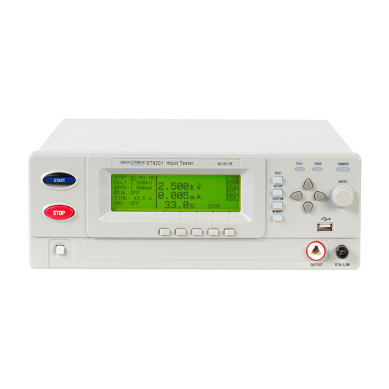
Page 15: Chapter 3 Part Names And Functions
Chapter 3 Part names and Functions This chapter describes the names and functions of components such as switches, displays, and connectors on the front and rear panels. Front Panel ST9201S HIPOT TESTER FAIL AC/DC/IR/SC PASS DANGER TEST START ENTRY SETUP SYSTEM STOP MEMORY... - Page 16 ● SYSTEM Press the key, and the corresponding key lights, display SYSTEM1 setting interface; It can be switched to SYSTEM2, SYSTEM3 and INTERFACE. ● MEMORY Press the key in the SETUP page, and the corresponding key lights, the SAVE window is used to save the currently edited test programm; while the LOAD window is used to retrieve saved data, you can set the selected data as the default scheme.
-
Page 17: Instruction Of Rear Panel
Instruction of rear panel UNDER RESET TEST START GPIB OUTPUT START SCANNER WARNING: FOR CONTINUED PROTECTION AGAINST FIRE HAZARD,REPLACE ONLY WITH THE SAME TYPE AND RATING OF FUSE RESET AS SPECIFIED FOR THE LINE VOLTAGE BEING UTILIZED. CAUTION: PASS FAIL NO OPERATOR SERVICEABLE PARTS INSIDE REFER SERVICING TO QUALITIFIED PERSONNEL. -
Page 18: Description
the place where DUT is connected with low terminal. SCAN interface Be used to connect ST9121 multi-channel tester. SBOX control program is needed to be customized. Backup interface 1. IEEE488 (GPIB) parallel communication interface. (Option) 2. ST10203 control interface (Option): it includes all functions of HANDLER interface. - Page 19 Each scanner can adopt 8 channels. The tester can be connected to two scanners, reaching up to 16 channels in total. ST9201 series all allocate PLC interface, RS-232C, GPIB (optional), thus the instrument can adapt to the auto test system of different required safety and reliability.
- Page 20 5kV/10mA(ST9201/S) 5kV/5mA(ST9201B/C) ST9201 series can provide DC withstanding voltage test of wide voltage range (Max. output voltage is 6kV). Instrument allocates a reliable, low ripple DC/AC switch circuit, voltage load adjusting rate≤1%+10V. When the voltage is between 50-500V, low load impedance may cause unstable output voltage, set the hardware automatic voltage regulation function as OFF and the voltage regulation factor is 10%.
- Page 21 ST9201S have internal multi-channels, in withstanding voltage test and insulation resistance, it can control 8 channels to test 8 points. Each channel can be connected to HI/LO/OPEN voltage. ST9201 series can be connected with ST9121 multi-channels scanner with 8 channels. ST9201 series can be 2...
- Page 22 16 channels simultaneously. ■ Waiting time setup function ST9201 series can set the test waiting time from 0.1s to 99.9s by a resolution of 0.1s. In this period, the tester will output TEST control signals. They are used to control external devices and ensure a reliable connection.
- Page 23 ■ Easy operation ST9201 series are quite easy to be operated. In the setup interface, the test condition is listed. Set test condition, use direction keys to select a topic from the LCD display, then rotate code switch. Shortcut key can select the set topic.
- Page 24 Instruction for options: ■ High voltage output terminal on the rear panel (Optional) On the rear panel, there is an optional high voltage output which is used for high voltage output of scanner. ! WARNING: The instrument applies 5kV AC/DC high voltage, so do not touch the DUT and test line, or it will cause the danger of electric shock.
-
Page 25: Chapter 4 Basic Operation
Chapter 4 Basic operation Interface structure overview This chapter describes the operation of withstanding voltage and insulation resistance. The following figure is the interface structure: SETUP STEP: 01/01 INS, DEL, NEW withstanding (AC withstan- voltage) ding voltage) AC parameters OS (open/short) SYSTEM SYSTEM1 SYSTEM1... -
Page 26: Instruction Of Interface Function
withstanding voltage test parameters. The third column in the interface is the function toggle interface. When some function lablels are selected in the second interface, the corresponding functions can be changed and their relative parameters will also vary. For instance, changing AC to DC, the tester will change from the AC withstanding voltage test mode to the DC withstanding voltage test mode, and the current AC parameter will be changed into DC parameter. -
Page 27: Setup
There are mainly 4 function keys which are SETUP, TEST, SYSTEM, MEMORY. 4.2.1 SETUP STEP: 01/01 SCAN: 1X2X3X4X5X6X7X8X VOLT: 0.050 RISE: LOCK UPPER: 1.000 FALL: OFST LOWR: REAL: TIME: FREQ: ARC: Figure 4.2.1 AC setup interface Instruction: STEP: 01/01 Test procedure: current setting No. / total items. Function Instruction Within the current test programme (PROG), it adds a new test item. -
Page 28: Test (Take Ac For Example)
4.2.2 TEST (Take AC for example) STEP: 01/01 SCAN: 1X2X3X4X5X6X7X8X VOLT: 1.000 LOCK 0.000 UPPER: 5.000 OFST LOWR: 0.0 0 0 mA TIME: ARC: LOCK Figure 4.2.2 AC test Note: 1. The high voltage can only be started on this interface to test high voltage. - Page 29 Instruction: Label Instruction Definition PASS HOLD: 0.2S~99.9S Pass judge hold time. Press STOP key to quit holding. STEP HOLD: 0.2S~99.9S Waiting time. Press ‘START’ to test the next item. AUTO RANG: ON, OFF Automatically switch the range 0.6s before test end. GR CONT: No GND contact test in low terminal.
- Page 30 SYSTEM 3 Interface SYSTEM3 PRE JUDGE: TURNMODE LOCK ARC MODE: DATA NO JUDGE OFST CH CHECK SAVE 4.2.3.3 SYSTEM3 Instruction: Label Instruction Definition PRE JUDGE OFF: do not distinguish between the primary and secondary test. 1-50 Final step number of the primary test: once the step number is selected, the primary tests ends in this step.
-
Page 31: Memory
Instruction: GPIB ADD: Communication interface address. BAUD: 9600 Communication interface baud rate.. 19200 DATA: Communication interface data digit. STOP: Communication interface stop digit. PARITY: Communication interface even odd check. NONE 4.2.4 MEMORY In Setup interface, press MEMORY key and then the window listed as below is displayed: (take AC interface for example) 01/01 1X2X3X4X5X6X7X8X... - Page 32 Instruction: Label Instruction Definition SN of memory. 00~49 Default Default interface Name programme. Only NAME: 8 digits modified in this interface. current memory Black STEP: available. The number of item saved in 00~99 memory. Operator selects the memory and fill in the file name, press F4 (ENTER) to enter dialog box to confirm.
- Page 33 View files The left column are interior storage files which can be scanned through the direction key or rotary knob. The right column are USB storage files which can be scanned through the direction key or rotary knob. If there is no USB disk inserted, No USB Disk will be prompted as shown below: RAM FILE USB FILE ...
- Page 34 Press F5 (ALT) to select all the files or not. If the cursor is in the RAM FILE area, press F5 key to select all or none of the non-empty files in the RAM FILE area. As shown below: RAM FILE USB FILE √...
-
Page 35: Test Item Interface And Parameter Setup
4.3 Test item interface and parameter setup 4.3.1 AC withstanding voltage test parameter setup: STEP: 01/01 SCAN: 1X2X3X4X5X6X7X8X VOLT: 0.050 RISE: UPPER: 1.000 FALL: OFST REAL: LOWR: 0.001 TIME: 0. 5 FREQ: ARC: Figure 4.3.1 AC setup interface Instruction of AC test parameters: VOLT: 0.050~5.000kV... -
Page 36: Insulation Resistance Test Parameter Setup
high voltage LOWR: OFF~0.1µA~10.00mA Current low limit value of DC withstanding voltage TIME: OFF~0.1~999.9S Test time of DC withstanding voltage ARC: OFF~0.1~10.0 mA Current Max. value of DC arc RISE: OFF~0.1~999.9S Voltage rising time of DC high voltage FALL: OFF~0.1~999.9S Voltage falling time of DC high voltage test WAIT:... -
Page 37: Open And Short Detection Test Parameter Setup
4.3.4 Open and short detection test parameter setup: STEP: SCAN: 1X2X3X4X5X6X7X8X OPEN: LOCK SHRT: OFST STAN: NONE Figure 4.3.4 OS setup interface Instruction of OS test parameters: OPEN: 10%~100% Percentage of open judge value of standard value SHRT: OFF~100%~500% Percentage of short judge value of standard value STAN: Previous standard... -
Page 38: Mf Multichannel Assist Control Setup (Only Used In Multichannel Test Instruments)
Example: take a 3-coil inductance as an example: 1-2 capacitance of about 300P, 1-3 capacitance of about 200P and 2-3 may be in short-circuit. After short circuit, the capacitance of 1-2 and 1-3 are in parallel connection. 1. Do not connect any measured piece and perform GET:, result is e.g. STAN = 100P, note down the open value. - Page 39 NOTE: The multi-channel equipment must be restructuring when using this function. It is recommended to buy a complete set of the instruments. This function is an auxiliary function of the multi-channel withstand voltage meter in order to realize the ST90010 test system connection. Refer to the ST90010 system description for details.
-
Page 40: Test Function Theory And Instruction
Test function theory and instruction This section describes the principle and use of the test for ground connection, ground current detection, and arc detection in the order of the test procedure. Start test Ground test Test voltage Ground rising current detection Charge current detection... -
Page 41: Start Up Test
4.4.1 Start up test In measurement mode, after checking the test conditions and the correct connection with DUT, press START key to start up test. After the delay set by STRT DLY1 and STRT DLY2 in SYSTEM2, the tester will start measurement. 4.4.2 Low terminal connection test Ground connection is used in testing device, as the low test terminal is connected to the ground terminal (shell),... -
Page 42: Dc Charging Current Detection
4.4.4 DC charging current detection This function is used to judge the connection of DUT. DUTs are generally capacitive components. In DC mode, the distributed capacitor will be charged at the voltage rise time (when the measurement starts) and its current will be much larger than the tested current being set. -
Page 43: Current Over Limit And Arc Detection (Arc) Function
4.4.8 Current over limit and arc detection (ARC) function Current over limit is divided as:current low and high limit, current range over limit, arc detection. Current low limit judge (LOW): generally for judging low terminal break. When instrument tests device, there must be a certain leakage current, when the leakage current is smaller than the set current value, it means fail, if the leakage current of DUT is quite small, then it is not necessary to turn off the function. -
Page 44: Fail Judgment
has to be filtered, so the analyze response rate is 0.1s class. Zone B: sampling analyze circuit rate is too slow, and long-time over- flow may cause damage of the DUT, as well as effect the output circuit. In circuit, current fast response circuit is added for compensating slow sampling response. -
Page 45: Stop
4.4.11 STOP In any test mode, if you press down the “STOP” button on the instrument, it will automatically end the test. When the test ends, no measurement result will be output. 4.4.12 OFFSET Before the test, due to the working environment and placement changes of test cables, there may some residual base numbers even when the instrument is testing without load. - Page 46 Figure 4.5.1: PLC Interface Structure and Timing NOTE: 1. In the TEST signal power mode Internal (switch position to the right, battery symbol), the PLC interface can output signals of 24V, where the real internal resistance is about 20Ω and the drive current is less than 30mA.
- Page 47 mode, and to ensure that TEST signal operation mode is in switch mode (switch position to the left, open switch symbol). 4.5.2 Simple indicating circuit diagram of HANDLER PLC NOTE: 1. DB9-<1-9> is the output signal identification for HANDLER interface, corresponding to the respective output.
- Page 48 Figure 4.5.3 Connection of HANDLER external Circuit 1. The above picture shows the connection circuit diagram of an external power source and the indicator lights, the TEST control switch of the instrument interface MUST be in switch mode. 2. When the load current is relatively large, use an external power supply. The TEST control switch of the instrument interface must be in switch mode.
-
Page 49: Chapter 5 St9201 Rs232 Commands
Chapter 5 ST9201 RS232 Commands Commands for System settings :SYSTem:VERSion? Inquires about the version of the tester. --Syntax: Command message: Query message: :SYST:VERS? --Example: :SYST:VERS? --Response message If the version of the tester is 1.00, Ver 1.00 is returned. :SYSTem:TIME:PASS Sets the pass hold time in a PASS judgment. - Page 50 :SYSTem:TIME:STEP Sets the step hold time . Also inquires about the current step hold time. --Syntax: Command message: :SYST:TIME:STEP <time> Query message: :SYST:TIME:STEP? --Program data: Data format: float Set value: 0.3~99.9 Resolution: 0.1 Unit: s --Example: To set the step hold time to 1.0s, :SYST:TIME:STEP 1.0.
- Page 51 :SYST:WRAN? If the current AUTO RANGE’s status is ON, ON is returned. :SYSTem:GCONtinuity Sets the GR CONT’s status. Also inquires about the current GR CONT’s status. --Syntax: Command message: :SYST:GCON <ON/OFF> or <1/0> Query message: :SYST:GCON? --Program data<ON/OFF>: Data format: Character Set value: 0 (OFF) , 1 (ON) --Example: To set the GR CONT’s status to ON,...
- Page 52 :SYST: GFI? If the current GFI’s status is ON, ON is returned. :SYSTem:BEEP Sets the buzzer volume. Also inquires about the current buzzer volume. --Syntax: Command message: :SYST:BEEP < ON/OFF/1/0 > Query message: :SYST:BEEP? --Program data: Data format:Integer Set value: 0~2 (0 is OFF) Resolution: 1 Unit: --Example:...
- Page 53 --Example: To set the LCD contrast to 4, :SYST:CR 4. --Example: :SYST:CR? If the current LCD contrast is 4, 4 is returned. :SYSTem:LOCK Sets the KEY LOCK’s status. Also inquires about the current KEY LOCK’s status. --Syntax: Command message: :SYST:LOCK <ON/OFF> or <1/0> Query message: :SYST:LOCK? --Program data<ON/OFF>:...
- Page 54 To set the AFTR FAIL’s status to STOP, :SYST:FAIL STOP. --Example: :SYST: FAIL? If the current AFTR FAIL’s status is STOP, STOP is returned. :SYSTem:SDLY1 Sets the value of STRT DLY1. Also inquires about the current STRT DLY1’s value --Syntax: Command message: :SYST:SDLY1 <data>...
- Page 55 --Example: To set the RAMP JUDG’s status to ON, : SYST:RJUD ON :SYST:RJUD 1 --Example: :SYST: RJUD? If the current RAMP JUDG is ON, ON is returned. :SYSTem:OFFSET Sets the OFFSET’s status. Also inquires about the current OFFSET’s status. --Syntax: Command message: :SYST: OFFSET<ON/OFF>...
- Page 56 --Example: To set the DC50 AGC’s status to ON, :SYST:DAGC ON or :SYST:DAGC 1 --Example: :SYST: DAGC? If the current DC50 AGC’s status is ON, ON is returned. :SYSTem:DMODE Sets the DISP MODE’s status. Also inquires about the current DISP MODE’s status. --Syntax: Command message: :SYST:DMODE <PF/DATA>...
- Page 57 Set value: 8 digits Resolution: Unit: --Example: To set the part number to 20090501, :SYST:PART 20090501. --Example: :SYST:PART? If the current part number is 20090501, 20090501 is returned. :SYSTem:SDLY2 Sets the value of STRT DLY2. Also inquires about the current STRT DLY2’s value --Syntax: Command message: :SYST:SDLY2 <data>...
- Page 58 --Program data<sn>: Data format: Integer Set value: 0~20 (0 is OFF) Resolution: 1 Unit: --Example: To set the PRE JUDGE’s status to OFF, :SYST:PJDG 0 --Example: :SYST: PJDG? If the current PRE PJDG is OFF, OFF is returned. :SYSTem:TURN Sets the TURN MODE’s status. Also inquires about the current TURN MODE’s status.
- Page 59 Query message: :SYST: ARC? --Program data<DATA/LEVEL>: Data format: Enum Set value: DATA, LEVEL --Example: To set the ARC MODE’s status to DATA, :SYST: ARC MODE DATA --Example: :SYST: ARC? If the current ARC MODE’s status is DATA, DATA is returned. :SYSTem:NJDG Sets the NO JUDGE’s status.
-
Page 60: Commands For Ac Settings
Query message: :SYST:CCHK? --Program data<ON/OFF>: Data format: Character Set value: 0 (OFF) , 1 (ON) --Example: To set the CH CHECK’s status to ON, :SYST:CCHK ON or :SYST:CCHK 1 --Example: :SYST: CCHK? If the current CH CHECK’s status is ON, ON is returned. - Page 61 --Syntax: Command message: SOUR:SAFE:STEP <sn>:AC:LEV < voltage > Query message: :SOUR:SAFE:STEP <sn>:AC:LEV? --Program data<sn>: Data format: Integer Set value: 1~49 Resolution: 1 Unit: --Program data<voltage>: Data format: float Set value: 50~5000 Resolution: 1 Unit: V --Example: To set the test voltage for step 1 to 1000, :SOUR:SAFE:STEP 1:AC:LEV 1000.
- Page 62 Data format: float Set value: 0~30.000E-3 (0 is OFF) Resolution: 1.000E-6 Unit: A --Example: To set the LOWER current for step 1 to 0.001, :SOUR:SAFE:STEP 1:AC:LIM:LOW 0.001. --Example: :SOUR:SAFE:STEP 1:AC:LIM:LOW? If the current LOWER current for step 1 is 0.001, 0.001 is returned.
- Page 63 :SOURce:SAFEty:STEP:AC:LIMit:ARC Sets the ARC current for ACW test. Also inquires about the ARC current. --Syntax: Command message: :SOUR:SAFE:STEP <sn>:AC:LIM:ARC <current> Query message: :SOUR:SAFE:STEP <sn>:AC:LIM:ARC? --Program data<sn>: Data format: Integer Set value: 1~49 Resolution: 1 Unit: --Program data<current>: Data format: float Set value: 0~15.0E-3 (0 is OFF) Resolution: 1.000E-4 Unit: A...
- Page 64 Resolution: 1 Unit: --Program data<current>: Data format: float Set value: 0~30.000E-3 (0 is OFF) Resolution: 1.000E-6 Unit: A --Example: To set the REAL current for step 1 to 0.001, :SOUR:SAFE:STEP:AC:LIM:REAL 0.001. --Example: :SOUR:SAFE:STEP:AC:LIM:REAL? If the current REAL current for step 1 is 0.001, 0.001 is returned.
- Page 65 If the current RISE time for step 1 is 1, 1 is returned. :SOURce:SAFEty:STEP:AC:TIME:FALL Sets the FALL time for ACW test. Also inquires about the FALL time. --Syntax: Command message: SOUR:SAFE:STEP <sn>:AC:TIME:FALL <time> Query message: SOUR:SAFE:STEP <sn>:AC:TIME:FALL? --Program data<sn>: Data format: Integer Set value: 1~49 Resolution: 1 Unit:...
- Page 66 Set value: 1~49 Resolution: 1 Unit: --Program data<time>: Data format: float Set value: 0~999.9 (0 is OFF) Resolution: 0.1 Unit: s --Example: To set the TEST time for step 1 to 1, :SOUR:SAFE:STEP 1:AC:TIME:TEST 1. --Example: :SOUR:SAFE:STEP 1:AC:TIME:TEST? If the current TEST time for step 1 is 1, 1 is returned.
-
Page 67: Commands For Dc Settings
:SOUR:SAFE:STEP :AC:TIME:FREQ? If the current test frequency for step 1 is 50, 50 is returned. :SOUR:SAFE:STEP:AC:CHAN Sets HIGH/LOW/OPEN for the scanner channel for ACW test. Also inquires about the set value for the scanner channel. --Syntax: Command message: SOUR:SAFE:STEP <sn>:AC:CHAN <channel>: <HIGH/LOW/OPEN>... - Page 68 Also inquires about the test voltage. --Syntax: Command message: SOUR:SAFE:STEP <sn>:DC:LEV <volt> Query message: :SOUR:SAFE:STEP <sn>:DC:LEV? --Program data<sn>: Data format: Integer Set value: 1~49 Resolution: 1 Unit: --Program data<volt>: Data format: float Set value: 50~6000 Resolution: 1 Unit: V --Example: To set the test voltage for step 1 to 1000, :SOUR:SAFE:STEP 1:DC:LEV 1000.
- Page 69 --Program data<current>: Data format: float Set value: 0~10.000E-3 (0 is OFF) Resolution: 1.000E-6 Unit: A --Example: To set the LOWER current for step 1 to 0.001, :SOUR:SAFE:STEP 1:DC:LIM:LOW 0.001. --Example: :SOUR:SAFE:STEP 1:DC:LIM:LOW? If the current LOWER current for step 1 is 0.001, 0.001 is returned.
- Page 70 If the current UPPER current for step 1 is 0.001, 0.001 is returned. :SOURce:SAFEty:STEP:DC:LIMit:ARC Sets the ARC current for DCW test. Also inquires about the ARC current. --Syntax: Command message: :SOUR:SAFE:STEP <sn>:DC:LIM:ARC <current> Query message: :SOUR:SAFE:STEP <sn>:DC:LIM:ARC? --Program data<sn>: Data format: Integer Set value: 1~49 Resolution: 1 Unit:...
- Page 71 Data format: Integer Set value: 1~49 Resolution: 1 Unit: --Program data<time>: Data format: float Set value: 0~999.9 (0 is OFF) Resolution: 0.1 Unit: s --Example: To set the RISE time for step 1 to 1, :SOUR:SAFE:STEP 1:DC:TIME:RAMP 1. --Example: :SOUR:SAFE:STEP 1:DC:TIME:RAMP? If the current RISE time for step 1 is 1, 1 is returned..
- Page 72 --Example: :SOUR:SAFE:STEP 1:DC:TIME:FALL? If the current FALL time for step 1 is 1, 1 is returned. :SOUR:SAFE:STEP:DC:TIME:TEST Sets the test time for DCW test. Also inquires about the test time. --Syntax: Command message: SOUR:SAFE:STEP <sn>:DC:TIME:TEST <time> Query message: SOUR:SAFE:STEP <sn>:DC:TIME:TEST? --Program data<sn>: Data format: Integer Set value: 1~49...
- Page 73 --Program data<sn>: Data format: Integer Set value: 1~49 Resolution: 1 Unit: --Program data<time>: Data format: float Set value: 0~999.9 (0 is OFF) Resolution: 0.1 Unit: s --Example: To set the WAIT time for step 1 to 1, :SOUR:SAFE:STEP 1:DC:TIME:DWEL 1. --Example: :SOUR:SAFE:STEP 1:DC:TIME:DWEL? If the current WAIT time for step 1 is 1,...
- Page 74 :SOUR:SAFE:STEP :DC:CLOW ON. --Example: :SOUR:SAFE:STEP :DC:CLOW? If the current CHECK LOW’s status for step 1 is ON, ON is returned. :SOUR:SAFE:STEP:DC:CHAN Sets HIGH/LOW/OPEN for the scanner channel for DCW test. Also inquires about the set value for the scanner channel. --Syntax: Command message: SOUR:SAFE:STEP...
-
Page 75: Commands For Ir Settings
Commands for IR Settings :SOURce:SAFEty:STEP:IR:LEVel Sets the test voltage for IR test. Also inquires about the test voltage. --Syntax: Command message: SOUR:SAFE:STEP <sn>:IR:LEV <volt> Query message: :SOUR:SAFE:STEP <sn>:IR:LEV? --Program data<sn>: Data format: Integer Set value: 1~49 Resolution: 1 Unit: --Program data<volt>: Data format: float Set value: 50~1500 Resolution: 1... - Page 76 Data format: Integer Set value: 1~49 Resolution: 1 Unit: --Program data< resistance >: Data format: float Set value: 1.0E5~5.0E10 Resolution: 1.0E5 Ω Unit: --Example: To set the LOWER resistance for step 1 to 1000000, :SOUR:SAFE:STEP 1:IR:LIM:LOW 1000000. --Example: :SOUR:SAFE:STEP 1:IR:LIM:LOW? If the current LOWER resistance for step 1 is 1000000, 1000000 is returned.
- Page 77 :SOUR:SAFE:STEP 1:IR:LIM:HIGH 1000000. --Example: :SOUR:SAFE:STEP 1:IR:LIM:HIGH? If the current UPPER resistance for step 1 is 1000000, 1000000 is returned. :SOUR:SAFE:STEP:IR:TIME:RAMP Sets the RISE time for IR test. Also inquires about the RISE time. --Syntax: Command message: SOUR:SAFE:STEP <sn>:IR:TIME:RAMP <time> Query message: SOUR:SAFE:STEP <sn>:IR:TIME:RAMP? --Program data<sn>: Data format: Integer...
- Page 78 SOUR:SAFE:STEP <sn>:IR:TIME:FALL? --Program data<sn>: Data format: Integer Set value: 1~49 Resolution: 1 Unit: --Program data<time>: Data format: float Set value: 0~999.9 (0 is OFF) Resolution: 0.1 Unit: s --Example: To set the FALL time for step 1 to 1, :SOUR:SAFE:STEP 1:IR:TIME:FALL 1. --Example: :SOUR:SAFE:STEP 1:IR:TIME:FALL? If the current FALL time for step 1 is 1,...
- Page 79 To set the TEST time for step 1 to 1, :SOUR:SAFE:STEP 1:IR:TIME:TEST 1. --Example: :SOUR:SAFE:STEP 1:IR:TIME:TEST? If the current TEST time for step 1 is 1, 1 is returned. :SOUR:SAFE:STEP:IR:AGC Sets the AGC’s status for IR test. Also inquires about the AGC’s status --Syntax: Command message: SOUR:SAFE:STEP <sn>:IR:AGC <ON/OFF>...
-
Page 80: Commands For Os Settings
<HIGH/LOW/OPEN> Query message: SOUR:SAFE:STEP <sn>:IR: CHAN <channel>? --Program data<sn>: Data format: Integer Set value: 1~49 Resolution: 1 Unit: --Program data< channel >: Data format: Integer Set value: 1~8 Resolution: 1 Unit: --Program data<HIGH/LOW/OPEN>: Data format: Character Set value: HIGH/LOW/OPEN Resolution: Unit: --Example: To set the scanner channel 1 for step 1 to HIGH,... - Page 81 Unit: --Program data<set value>: Data format: float Set value: 0.1~1.0 Resolution: 0.1 Unit: --Example: To set the OPEN rate for step 1 to 50%, :SOUR:SAFE:STEP 1:OS:OPEN 0.5. --Example: :SOUR:SAFE:STEP 1:OS:OPEN? If the OPEN rate for step 1 is 50%, 0.5 is returned. : SOUR:SAFE:STEP:OSC:SHOR Sets the SHORT rate for OS test.
-
Page 82: Other Commands
2 is returned. :SOUR:SAFE:STEP:OS:CHAN Sets HIGH/LOW/OPEN for the scanner channel for OS test. Also inquires about the set value for the scanner channel. --Syntax: Command message: SOUR:SAFE:STEP <sn>:OS:CHAN <channel>: <HIGH/LOW/OPEN> Query message: SOUR:SAFE:STEP <sn>:OS: CHAN <channel>? --Program data<sn>: Data format: Integer Set value: 1~49 Resolution: 1 Unit:... - Page 83 --Example: :SOUR:SAFE:START :SOUR:SAFE:STOP Stops a test. Also cancels FAIL,PASS,STOP status. --Syntax: Command message: :SOUR:SAFE:STOP --Example: :SOUR:SAFE:STOP : SOUR:SAFE:LOAD Recalls the contents of memory stored before. --Syntax: Command message: SOUR:SAFE:LOAD <sn> --Program data<sn>: Data format: Integer Set value: 1~49 Resolution: 1 Unit: --Example: To recall memory 1,...
- Page 84 *IDN? ST9201 Ver:1.0 is returned. : TEST:DATAI? Inquires about the monitor current during the ACW/DCW test. --Syntax: :TEST:DATAI? --Unit: mA --Example: :TEST:DATAI? If the present monitor current in an ACW test is 1.00, 1.00 is returned. : TEST:DATAR? Inquires about the monitor resistance during the IR test. --Syntax: :TEST:DATAR? --Unit: MΩ...
- Page 85 --Response message: Status value, voltage value, current or resistance value ----Program data< status >: 0 (READY) 1 (TEST) 2 (PASS) 3 (FAIL) 4 (STOP) ----Program data< voltage value >: Data format: Integer Resolution: 1 Unit: V ----Program data< current or resistance value >: Data format: float Unit: mA/MΩ...
- Page 86 :ALLSET3 <func>,<scan>,<open>,<shrt>,<stan> 5 items, see parameters list. --Response message: ‘1’ if the command was valid. Parameters list: Items Type Function Detail func enum Setup functions 0--None; 1--AC; 2--DC; 3--IR; 4--OS scan Setup channel Bit mask for channel selection, see Note1 volt float Setup voltage...
- Page 87 To setup ch1 high, the 16-bit value of scan is 0000 0000 1000 0000 (0x0080). To setup ch8 low, the 16-bit value of scan is 0000 0001 0000 0000 (0x0100). --Example: :ALLSET3 1,0,50,10,0,5,0,0,50,1,1,0 is equal to: :ALLSET3 1,0,0,0,0,0,0,0,0,0,0,0 :SOUR:SAFE:STEP 1:AC:LEV 50 :SOUR:SAFE:STEP 1:AC:LIM:HIGH 10 :SOUR:SAFE:STEP 1:AC:LIM:LOW 0 :SOUR:SAFE:STEP 1:AC:TIME:TEST 5...
-
Page 88: Chapter 6 St9201 Series Specification
Chapter 6 ST9201 series specification Model ST9201 ST9201S ST9201B ST9201C Withstanding voltage test Range 0.050kV—5.000kV Waveform Sinusoidal wave Distortion < 3% Frequency 50, 60Hz selectable Frequency ±2% accuracy Max. output 150VA (5.000kV 30mA) 100VA (5.000kV 20mA) power Range 0.050 kV—6.00kV... - Page 89 IR test Output voltage 0.050kV – 1.500kV Voltage resolution Voltage test accuracy ±(1.0% reading+2V) Max. output current 10mA Max. output power 10 VA (1000V/1mA) (1000V/1mA) Output short current ≥20mA ≥10mA Load regulation ≤1% (nominal power) Ripple (1kV) ≤3% (1kV, non-load) Discharge function Auto discharge after test ends Resistance...
- Page 90 Model ST9201X ST9201SX ST9201BX ST9201CX Withstanding voltage test Range 0.050kV—5.000kV Waveform Sinusoidal wave Distortion < 3% Frequency 50, 60Hz selectable Frequency ±2% accuracy Max. output 15VA (5kV/3mA) 15VA (5kV/3mA) power Range 0.050 kV—6.00kV ------ Signal source 600Hz ------ Output frequency voltage Max.
- Page 91 IR test Output voltage 0.050V – 1.500V Voltage resolution Voltage test accuracy ±(1.0% reading+2V) Max. output current 10mA Max. output power 10 VA (1000V/1mA) (1000V/1mA) Output short current ≥20mA ≥10mA Load regulation ≤1% (nominal power) Ripple (1kV) ≤3% (1kV, non-load) Discharge function Auto discharge after test ends Resistance...
- Page 92 Parameter setup Voltage rising time 0.1s – 999.9s Voltage down time 0.1s – 999.9s (only after the withstanding voltage test passes) 0.3s – 99.9s (only for DC withstanding voltage and rising time+ Voltage waiting time test time>waiting time) Test time setup 0.3s –...
- Page 93 Included accessories: ST90003R Withstanding voltage test clip ST90003B Withstanding voltage grounding clip ST90004 Withstanding voltage test rod Options ST9200-GPIB Interface board ST®Meter Basic RS232C communication control software ST®Meter Plus Extended RS232C communication control software ◇93...
- Page 94 SOURCETRONIC GMBH Fahrenheitstrasse 1 28359 Bremen Germany T +49 421 2 77 99 99 F +49 421 2 77 99 98 info@sourcetronic.com www.sourcetronic.com skype: sourcetronic www.sourcetronic.com...
Need help?
Do you have a question about the ST9201 Series and is the answer not in the manual?
Questions and answers