
Related Manuals for Sourcetronic ST2523


Summary of Contents for Sourcetronic ST2523
- Page 1 SOURCETRONIC − Quality electronics for service, lab and production User Manual Battery Tester ST2523/A...
-
Page 2: Table Of Contents
Contents Chapter 1 Introduction to Instrument, Unpacking and Installing ..........1 1.1 Introduction to the Instrument .................... 1 1.2 OOBA (Out of Box Audit) ...................... 1 1.3 Power Connections ......................1 1.4 Fuse ............................2 1.5 Environment ........................2 1.6 Use of Test Fixture........................ 2 1.7 Warm-up .......................... - Page 3 ST2523 Series Operation Manual Ver1.2 3.7.7 TOOLS .......................... 20 Chapter 4 System Setup and File Manage ................21 4.1 System Setup ........................21 4.1.1 Key Sound ........................21 4.1.2 Language ........................21 4.1.3 Password ........................21 4.1.4 Bus Mode ........................22 4.1.5 Baud Rate ........................
- Page 4 ST2523 Series Operation Manual Ver1.2 Chapter 7 SCPI Command Reference................... 38 7.1 ST2523 Subsystem Commands ..................38 7.1.1 DISPlay Subsystem Commands ................... 38 7.1.2 FUNCtion Subsystem Commands ................40 7.1.3 APERture Subsystem Commands ................45 7.1.4 TRIGger Subsystem Commands: ................. 45 7.1.5 FETCh? Subsystem Commands ...................
-
Page 5: Chapter 1 Introduction To Instrument, Unpacking And Installing
Caution: the low test terminal of ST2523/A is connected to the ground. When testing other device or components except batteries, or sending it to Bureau of Standard Measurement for calibration, please plan your measuring setup accordingly. -
Page 6: Fuse
ST2523 Series Operation Manual Ver1.2 1.4 Fuse The fuse is a standard configuration, so use the included custom fuse please. 1.5 Environment ( 1 ) Do not store or use the instrument where it could be exposed to many dusts, great vibration, direct sunshine and corrosive gas. -
Page 7: Chapter 2 Introduction To Front Panel And Operation
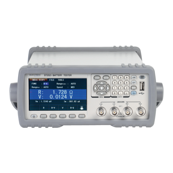
ST2523 Series Operation Manual Ver1.2 Chapter 2 Introduction to Front Panel and Operation This chapter will deal with basic operation procedures of ST2523. Before using the instrument, please read this chapter carefully. 2.1 Introduction to Front Panel Figure 2-1 shows the front panel of ST2523. -
Page 8: Introduction To Rear Panel
When the cursor stays in different area, the soft key area will display different function. (15) POWER Power switch. 2.2 Introduction to Rear Panel Figure 2-2 shows the rear panel of ST2523. WARNING TO AVOID ELECTRIC SHOCK, THE POWER CORD PROTECTIVE GROUNDING CONDUCTOR MUST BE CONNECTED TO GROUND. -
Page 9: Display Zones
Through HANDLER interface, an automatic test system can be conveniently constructed to realize auto test. ST2523 will output bin comparator result signals and handshake signals by this interface, meanwhile, “start up” signal will also be sent to the instrument by it. -
Page 10: Keys And Their Corresponding Display
<TRACE SETUP> <SYSTEM SETUP> 2.5 Basic Operations Basic operations of ST2523 keys are as follows : Choose the desired page by menu keys [DISP], [SETUP] and soft keys. Move the cursor to the destination zone by arrow keys ([←] [↑] [→] [↓]). -
Page 11: Starting Up
Figure 2-4 shows the boot screen of ST2523, indicating product information such as instrument trademark, model, and version. -
Page 12: Chapter 3 Basic Operations
ST2523 Series Operation Manual Ver1.2 Chapter 3 Basic Operations 3.1 <MEAS DISP> Press down [DISP], the <MEAS DISP> page will be displayed in the screen, as is shown in figure 3-1. Figure 3-1 Measurement Display The following measurement parameters can be set in this page. -
Page 13: Measurement Functions
There are two options in MEAS RANGE, which can be selected according to the impedance and the DC voltage of DUT. ST2523 series has 6 AC impedance measurement ranges: 30mΩ, 300mΩ, 3Ω, 30Ω, 300Ω, 3kΩ. ST2523 has 2 DC voltage measurement ranges: 6V, 60V. -
Page 14: Measurement Speed
Four measurement speeds are available on ST2523: FAST (fast, approx. 50meas/ sec), MED (medium, approx. 10meas/ sec) and SLOW (slow, approx. 6.25meas/ sec). Operation procedures are as follows: The measurement result is displayed as a 5-digit number in decimal point floating mode. The impedance parameter is displayed in fixed decimal point mode, while the inductance parameter is displayed in floating decimal point mode. -
Page 15: Bin Disp
ST2523 Series Operation Manual Ver1.2 Start Save/Stop Save: the current measurement results will be saved to a U disk. Until a U disk is inserted, the save function is disabled. : : Save operation: Be sure to press “Stop Save” to stop saving data after “Start Save” is pressed, otherwise data will be lost. - Page 16 ST2523 Series Operation Manual Ver1.2 Figure 3-3 Compare Display Page Mode: Compare and BIN. Compare: compare function of DUT; BIN: judgment of good or bad products. Sound: NG, GD and OFF. NG: not good product sound; GD: good product sound; OFF: sound is off.
-
Page 17: Trace Disp
ST2523 Series Operation Manual Ver1.2 3.3 <TRACE DISP> Press TRACE DISP in soft key area to enter into <TRACE DISP>. Touch TOOL, the following page will be displayed. Figure 3-4: Trace Display Page Move to TOOL, the following items will be displayed in the soft key zone: SCAN START: Press [SCAN START], trace scanning will start;... -
Page 18: Meas Setup
:AUTO : AUTO, HOLD, ↑, ↓will be displayed in the soft key zone by touching this key. Press one of them, resistance range will be automatically selected or locked. :A UTO : Move the cursor to it , AUTO, HOLD, 6V/60V (ST2523), 30V/300V Range ... -
Page 19: Trig
(bus trigger). When Trig is set to the INT mode, ST2523 will automatically make continuous measurement. When Trig is set to the MAN mode, ST2523 will make a measurement by each press of [TRIGGER] button on the front panel. When Trig is set to the EXT mode, ST2523 will make a measurement at each time the HANDLER interface receives a trigger signal. -
Page 20: Bin Setup
Press BIN SETUP in soft key area to enter into the <BIN SETUP> page shown in figure 3-6. Figure 3-6 Limit Setup Comparator functions can be set in this page. ST2523 can set 9 groups of nominal and limit values for primary and secondary parameters. -
Page 21: Trace Setup
For the accuracy of measurement result, two more measurements will be done when the instrument finds the measurement result exceeding its range, and then ST2523 will stop testing. If the “OFF” soft key is selected, the judge for the stop point will be switched off when scanning the trace. -
Page 22: Statis Disp
ST2523 Series Operation Manual Ver1.2 instrument finds the measurement result exceeding its range, and then ST2523 will stop testing. If the “OFF” soft key is selected, the judge for the stop point will be switched off when scanning the trace. -
Page 23: Statis A/Statis B
3.7.4 Statis A/Statis B Move the cursor to it and select through the soft key. When A is selected, ST2523 will compare the measurement result with the limit ranges of its primary parameter, count times of pass, times of higher and lower results;... -
Page 24: Tools
ST2523 Series Operation Manual Ver1.2 Hi(num): Be used to add up times that the measurement result exceeds the upper limit value. Lo(num): Be used to add up times that the measurement result is less than the lower limit value. In(num): Be used to add up times that the measurement result passes. -
Page 25: Chapter 4 System Setup And File Manage
ST2523 Series Operation Manual Ver1.2 Chapter 4 System Setup and File Manage 4.1 System Setup Press [DISP] and then press SYSTEM SETUP in soft key area to enter into the <SYSTEM SETUP> page shown in the following figure 4-1. Figure 4-1 System Setup Page The following functions can be set in this page: key Sound, Language, Password, Bus Mode, Baud Rate, Bus Addr and Time. -
Page 26: Bus Mode
ST2523 Series Operation Manual Ver1.2 ON: Enable the password protection function. The passwords are used to start up the instrument and to protect files. MODIFY: This key is used to modify password. ———————————————————————— NOTE: The default password is 2523. ————————————————————————... -
Page 27: Time
Press this key, the time will decrease by 5. 4.2 <File Manage> ST2523 series can save parameters that are set by user to the internal non-volatile memory in the file format. User can load the file to use these parameters instead of resetting. -
Page 28: Structure Of File Folder/ File In A U Disk
U disk. If the U disk memory exceeds 512M, it is recommended to use FAT32 standard to format the disk. 3. Before a U disk is connected to ST2523, you are recommended to save the data on it and Sourcetronic... - Page 29 ST2523 Series Operation Manual Ver1.2 will not be liable for the data loss. 4. In order to rapidly save the instrument data to a U disk, it is not recommended to store too many files or folders. Operation Procedures Press FILE and select INTER File to enter into the internal file page, as shown in below figure 4-3.
-
Page 30: Chapter 5 Performance Index
(rad radian) 5.1.2 Measurement Groups ST2523 has nine measurement groups: R, R-V, V, R-Q, L-Q, L-R, R-X, Z-, and Z-r. 5.1.3 Mathematical Operations Mathematical operations on ST2523 are options to display absolute value deviation (ΔABS) or percentage deviation (Δ%) between a measurement value and a programmable nominal value. -
Page 31: Display Digits
The test signal is a sinusoidal wave with the frequency of 1kHz±0.2Hz. 5.2.2 Maximum Input Voltage ST2523: The maximum input voltage that the test terminal can withstand is 65V. ST2523A: The maximum input voltage that the test terminal can withstand is 310V. -
Page 32: Basic Accuracy For Resistance Measurement
ST2523 Series Operation Manual Ver1.2 5.2.5 Basic Accuracy for Resistance Measurement SLOW, MED: (exceeding the temperature of 20ºC±5ºC; the temperature coefficient plus ±0.05%/ºC.) Model: ST2523 /ST2523A Display Digits: 5 Accuracy Range |Maximum Resolution Measurement 6 months 1 year display value| constant current mΩ... - Page 33 ST2523 Series Operation Manual Ver1.2 FAST: (exceeding the temperature of 20ºC±5ºC; the temperature coefficient plus ±0.005%/ºC.) Model: ST2523 Display digits: 4 Accuracy | Maximum display Range Resolution 6 months 1 year value| 6.500 V 0.1% 0.15% 60 V 65.00 V SLOW, MED: (exceeding the temperature of 20ºC±5ºC;...
-
Page 34: Chapter 6 Remote Control
As most serial interfaces, the serial interface of ST2523 is also not strictly based on RS-232 standard but only uses the smallest subset of this standard. The signals are listed in the following table. -
Page 35: Gpib Bus (Option)
ST2523 applies IEEE488.2 and the interface plate can be inserted in any one of the three expansion slots Control command system is open so that user can use the PC operation interface provided by ST2523 or take measurements by the control command system. The control command system supports most functions of the instrument, that is to say, user can execute almost all operations on PC. - Page 36 ST2523 Series Operation Manual Ver1.2 Test Instrument Piggyback Connector Figure 6-3 Typical GPIB System Interconnection for Double-piggyback Connector Figure 6-4 Typical GPIB System Interconnection for 4-piggyback Connector...
-
Page 37: Gpib Interface Functions
LOCAL LOCKOUT disables the LOCAL operation of all devices on the bus. After this command is sent, you will be unable to operate ST2523 from the front panel including the soft key LOCAL. Execute the LOCAL command to undo LOCAL LOCKOUT. -
Page 38: Scpi (Standard Commands For Programmable Instruments)
SRQ, deemed as an interruption, will inform the controller to prepare the transmitted data or that errors exist on the instrument. As soon as ST2523 sends a SRQ service request signal, it will set the status byte to 6. 6 bytes are RQS request service bytes and sometimes connects with serial poll to act as the status byte. -
Page 39: Usbtmc Remote Control System
Connect USB interfaces on PC and ST2523 through a USB cable. 6.3.2 Install the Driver When ST2523 is first connected to a PC through a USB cable, the prompt information –Found New Hardware will show on the right bottom of the computer desktop, as is shown below: Figure 6-10 Procedure 1 of Installing USB Driver Click “NEXT”, dialogue 6-11 will pop up. - Page 40 ST2523 Series Operation Manual Ver1.2 When the installation of driver is finished, user can see “usb test and measurement device” in the device manager of PC, as is shown in the following figure. Figure 6-12 USBTMC Display of PC Device Manager...
-
Page 41: Usbcdc Virtual Serial Port
When “USBCDC” is selected, the USB interface can be configured as a virtual serial port (VCom) Connect PC and ST2523 to the USB interface through a USB cable. Methods of installing USBCDC driver are the same with that of installing USBTMC driver. When the installation of driver is finished, user can see “usb VCom port”... -
Page 42: Chapter 7 Scpi Command Reference
ST2523 Series Operation Manual Ver1.2 Chapter 7 SCPI Command Reference 1. Data Conventions of This Manual NR1: integer, for example:123 NR2: fixed number, for example: 12.3 NR3: floating number, for example: 12.3E+5 NL: CR character, integer: 10 ^END: EOI (end) signal of IEEE-488 bus. - Page 43 ST2523 Series Operation Manual Ver1.2 Set the display page to bin setup (this command is invalid). BinSETup TSETup Set the display page to trace setup. Set the display page to system setup. SYSTem Set the display page to (internal) file list.
-
Page 44: Function Subsystem Commands
ST2523 Series Operation Manual Ver1.2 7.1.2 FUNCtion Subsystem Commands FUNCtion subsystem commands are mainly used to set “function”, “range”, “speed”, current and voltage monitoring switch, mode selection of deviation display, nominal setup, etc.. Command Tree: The :IMPedance command sets the “function” parameters. - Page 45 ST2523 Series Operation Manual Ver1.2 Details are as follows: Set “function” as R. Set “function” as V. Set “function” as R-V. Set “function” as R-Q. Set “function” as L-Q. Set “function” as L-R. Set “function” as R-X. Set “function” as Z-θ°.
- Page 46 ST2523 Series Operation Manual Ver1.2 Where, Character 1 (integer:49) means ON. Character 0 (integer: 48) means OFF. For example: WrtCmd(“FUNC:IMP:RANG:AUTO ON”); Set the range mode as auto. Query syntax: FUNCtion:IMPedance:RANGe:AUTO? Return format: <NR1><NL^END> The :VDC:RANGe command sets the range of DC voltage.
- Page 47 ST2523 Series Operation Manual Ver1.2 Where: Character 1 (integer:49) means ON. Character 0 (integer: 48) means OFF. For example: WrtCmd(“FUNC:SMON:VAC ON”); Set the voltage monitoring switch as “ON”. Query syntax: FUNCtion:SMONitor:VAC? Return format: <NR1><NL^END> The :Source MONitor:IAC command sets the current monitoring switch.
- Page 48 ST2523 Series Operation Manual Ver1.2 Query syntax: FUNCtion:DEV<n>:MODE? Return format: PERC <NL^END> The :DEV<n>:REFerence command sets the nominal value of deviation. The FUNCtion:DEV<n>:REFerence? query returns the current deviation nominal value. Command syntax: FUNCtion:DEV<n>:REFerence<value> Where: <value> may be a number in NR1, NR2 or NR3 format.
-
Page 49: Aperture Subsystem Commands
ST2523 Series Operation Manual Ver1.2 This command switches the short function to ON or OFF. Command syntax: :FUNC:SHORT ON Query syntax: :FUNC:SHORT? Return: 1(49) means ON. 0(48) meansOFF. :ACFREQuency This command is used to control the supply frequency. Command syntax: :FUNC:ACFREQuency 50... - Page 50 ST2523 Series Operation Manual Ver1.2 Command Tree: TRIGger [:IMMediate] :SOURce INTernal EXTernal HOLD :DELay <value> The :IMMediate command triggers a measurement. Command syntax: TRIGger[:IMMediate] For example: WrtCmd(“TRIG”); The :SOURce command sets the mode of trigger source. The :SOURce? query returns the current mode of trigger source.
-
Page 51: Fetch? Subsystem Commands
Query syntax: TRIGger:DELay? Return format: <NR3><NL^END> 7.1.5 FETCh? Subsystem Commands FETCh? subsystem commands are used to make ST2523 output a measurement result. Command syntax: FETCH? 7.1.6 COMParator Subsystem Commands: COMParator subsystem commands are used to set bin comparator functions, such as comparator ON/OFF, limit list. - Page 52 ST2523 Series Operation Manual Ver1.2 Query syntax: COMParator[:STATe]? Return format: <NR1><NL^END> The [:BEEper] command sets the beeper of comparator function. The COMParator[:BEEper]? query returns the current beeper status. Command syntax: COMParator: BEEper NotGood Good NotGood when the DUT fails, the buzzer beepers.
-
Page 53: Binsetup Subsystem Commands
ST2523 Series Operation Manual Ver1.2 7.1.7 BINSETup Subsystem Commands Binsetup Subsystem Commands are used to set the bin comparison and compare judgment condition. Command Tree: The:BINSETup:BinMode command set the bin compare mode. The:BINSETup:BinMode? query returns the current compare mode. Command syntax: BINSETup:BinMode ABS... - Page 54 ST2523 Series Operation Manual Ver1.2 The:BINSETup:COMPareB command set the secondary parameter as ON/OFF. The:BINSETup:COMPareB? query returns the current status of secondary parameter. Command syntax: BINSETup:COMPareB ON(1) OFF(0) set the secondary parameter function as ON OFF set the secondary parameter as OFF For example: WrtCmd(“BINSET: COMPB ON”)
- Page 55 ST2523 Series Operation Manual Ver1.2 Query syntax: BINSETup: BINA N? Return value: <NR3><NL^END> <NR3> the upper and lower limit of the primary parameter The:BINSETup:BINB command set the upper and lower limit of the secondary parameter. According to different modes, the upper and lower limit of absolute value or percentage can be set. The:BINSETup:BINB? query returns the current limit of current mode.
-
Page 56: Statistical Subsystem Commands
ST2523 Series Operation Manual Ver1.2 7.1.8 Statistical Subsystem Commands Statistical subsystem commands are used to count the measurement result or to set statistical funtion. Command Tree: The :STATIstics:STATe command sets the statistical function of primary parameter or secondary parameter to ON or OFF. - Page 57 ST2523 Series Operation Manual Ver1.2 The :STATIstics:STATUS command sets the statistical function to ON or OFF. Command syntax: : STATIstics:STATUS ON(1) OFF(0) Where, set the statistical function to ON OFF set the statistical function to OFF Query syntax: :STATIstics:STATUS? Response: <NR1> <NL^END>...
- Page 58 ST2523 Series Operation Manual Ver1.2 The : STATIstics:MAXimum? query returns the maximum value of statistical results. Query syntax: : STATIstics:MAXimum? Response: <maximum (NR3), serial number corresponding to the maximum (NR1)> For example: Query: :STATI: MAX? Response: 1.2450E+01, 5 The : STATIstics:MINimum? query returns the minimum value of statistical results.
- Page 59 ST2523 Series Operation Manual Ver1.2 The : STATIstics:DEViation? query returns the statistical deviation. Query syntax: : STATIstics:DEViation? Response: <σn(NR3)> For example: Syntax: :STATI:DEV? Response: 0.0159E-3 The : STATIstics:VARiance? query returns the statistical variance. Query syntax: : STATIstics: VARiance? Response: <sn(NR3)>...
-
Page 60: Trace Subsystem Commands
ST2523 Series Operation Manual Ver1.2 7.1.9 TRACe Subsystem Commands The :TRACe:TOTAL <value> command is used to set and return the total time of scanning. For example: :TRACe:TOTAL Query syntax: :TRACe:TOTAL? Response: <value NR2> The TRACe:INTERval <value> command is used to set and return the interval time between trace scanning. -
Page 61: System Subsystem Commands
ST2523 Series Operation Manual Ver1.2 For example: :TRACe:BM 5.1600E+01,1.0000E+01 Query syntax: :TRACe:BM? Response: <max value NR3>, <min value NR3> The :TRACe:ASTOP1 OFF <value> :TRACe:ASTOP2 OFF <value> :TRACe:BSTOP1 OFF <value> :TRACe:BSTOP2 <value> commands are used to set or return the stop point of trace scanning. -
Page 62: Mass Memory Subsystem Commands
ST2523 Series Operation Manual Ver1.2 This command sets and returns Beep Tone. For example: :SYST:BEEP OFF Turn off beep tone. Query syntax: :SYST:BEEP? Response: <NR1><NL^END> <NR1> is 0 Turn off beep tone. Turn on beep tone. 7.1.11 Mass MEMory Subsystem Commands Mass MEMory subsystem commands are used to save and load files (only for internal files). -
Page 63: Gpib Common Commands
For example: WrtCmd(“*IDN?”); The *TST? query executes an internal self test and returns the test result as the sum of all existing errors codes. If there are no error ST2523 returns 0. Query syntax: *TST? Return format: 0<NL^END> Where, 0 0 (NR1 format) For example: WrtCmd(“*TST?”);... - Page 64 ST2523 Series Operation Manual Ver1.2 Request Control(RQC) Bit Operation Complete(OPC) Bit Query syntax: *ESE? Return format: <value><NL^END> For example: WrtCmd(“*ESE?”); The *SRE (Service Request Enable command) command sets each open bit of the service status byte register. This command returns the current setups for each open bit of the status byte permission register.
- Page 65 MAV(Message Available) Bit Always 0(zero) For example: WrtCmd(“*STB?”); The *OPC command equals to set the OPC bit of the standard event status register when ST2523 finishes all parameter measurements. Ever since all pending operations have been completed, this command will inform the instrument to add a ASCII number “1”...
-
Page 66: Chapter 8 Handler Interface
Ver1.2 Chapter 8 Handler Interface ST2523 AC milliohmmeter equips with a Handler interface which is mainly used to output the sorting result. When the instrument is applied to an automatic component sorting test system, this interface will output the handshake signal and the sorting result output signal. - Page 67 ST2523 Operation Manual Ver1.2 active bin comparison result output signal is effective. /PLO The main parameter is lower: the low active bin comparison result output signal is effective. /PIN The main parameter PASS: the low active bin comparison result output signal is effective.
- Page 68 ST2523 Operation Manual Ver1.2 Timing chart:...
-
Page 69: Chapter 9 Package Contents And Warranty
ST2523 Operation Manual Ver1.2 Chapter 9 Package Contents and Warranty 9.1 Package Contents Following items should be contained in the package. ST2523 Battery Tester ST26011A 4-terminal Kelvin clip test cable Three-Wire power line fuse of 1A Operation Manual Manufacturer Certificate... -
Page 70: Storage
9.6 Warranty This Sourcetronic instrument is warranted against defects in material and workmanship for a period of two years from the date of shipment. You should supply us with the warranty card before you enjoy the free maintenance service. This warranty does not apply in the event of misuse or abuse of the product or as a result of unauthorized alterations or repairs. - Page 71 SOURCETRONIC GMBH Fahrenheitstrasse 1 28359 Bremen Germany T +49 421 2 77 99 99 F +49 421 2 77 99 98 info@sourcetronic.com www.sourcetronic.com skype: sourcetronic www.sourcetronic.com...
Need help?
Do you have a question about the ST2523 and is the answer not in the manual?
Questions and answers