Table of Contents
Advertisement
Quick Links
Advertisement
Table of Contents

Subscribe to Our Youtube Channel
Related Manuals for Sourcetronic TM-25R


Summary of Contents for Sourcetronic TM-25R
- Page 1 High-frequency earth tester • User guide • Technical specifications...
- Page 2 TM-25R High-frequency earth tester User guide GU-1535...
- Page 3 Safety warnings As the line is energized and the tower grounding state is, provisionally unknown, the operator shall follow all the safety measures stated, avoiding the existence of step and touch voltages which are possibly dangerous. Refer to the company safety regulations for these matters. This equipment should be used only by a trained and competent person, strictly applying suitable safety rules.
-
Page 4: Table Of Contents
3.1.1. Battery description ................10 3.1.2. Battery status check ................10 3.1.3. Recharge procedure................10 4. Printer ......................11 5. Connecting the TM-25R ................... 12 5.1. Equipment location ................... 12 5.2. Auxiliary rods set up ................. 12 6. Measuring ......................13 6.1. -
Page 5: Description
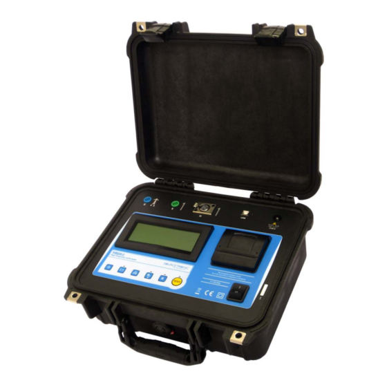
SOURCETRONIC TM-25R grounding resistance tester for high frequency has been developed. This is the appropriate tool for a fast, safe and reliable grounding resistance measurement in each tower of a working line transmission, without disconnecting the ground wire. - Page 6 GPS coordinates of each. Also allows you to record voice annotations to each measurement TM-25R is powered by a built-in rechargeable battery. It is a rugged, easy to carry, resistant to the hard weather and geographical features of the...
-
Page 7: Control Panel
2. Control panel All of the TM-25R buttons, keys, outputs and connections are located on the panel, and are easily accessible by the operator. The following graphics show the function of each one of the equipment’s items. 2.1. Connections and items... -
Page 8: Keyboard
2.2. Keyboard Earth Resistance f= 25kHz 01/01/2014 17:21 Function It prints the last test performed – It shows the battery charge status on the The battery charger is display operating Backlight - it activates the display light. After – 10 seconds the backlight will auto-turn off in order to save the battery charge It selects the grounding resistance It indicates selected... -
Page 9: Power Supply
To recharge the battery: • Check if the TM-25R is off, and then connect it to the 110 V or 220 V mains supply (using the AC Adapter). -
Page 10: Printer
4. Printer Pressing the key will print the results and parameters of the last test. ATTENTION: Don’t pull the paper. The printer can be easily damaged. This printer uses 57 mm-wide thermal paper. Pull the lever located on the lid. Insert the paper reel as shown in the figure. -
Page 11: Connecting The Tm-25R
5. Connecting the TM-25R 5.1. Equipment location The equipment shall be placed as close as possible to the tower support where the grounding is located, and it will be connected to the instrument E terminal. 5.2. Auxiliary rods set up... -
Page 12: Measuring
6. Measuring 6.1. Selecting the type of measurement TM-25R measures grounding resistance with without compensation of the inductive component. 6.1.1. Grounding resistance measurement Select the grounding resistance measurement by pressing the key. • When the equipment is switched on, this function is automatically selected. - Page 13 Note: If the system tuning is not obtained (normally because the inductance of the grounding systems is not significant), this will be shown in the display. R= 9.04 Rc= ___ C= ___ L= 0 01/01/2014 17:21 If the test is printed, the message “Undefined” for the values Rc and C, with L= 0 will be displayed.
-
Page 14: Looking For The Potential Profile Flat Area
6.2. Looking for the potential profile flat area After getting the first Grounding Resistance Value, it is necessary to obtain the greatest amount of points to trace the potential profile curve. In order to do that, the potential rod (probe) should be always set up perpendicular to the traced line, in several intermediate points between the unknown electrode and the current rod, so as to obtain the kind of curve showed below. -
Page 15: Abnormalities Indications On The Display
7. Abnormalities indications on the display If the TM-25R identifies any abnormality causing the measurements to be excessively inaccurate, or not possible at all, a warning message will be shown on the display, allowing the operator to identify and correct the problem. -
Page 16: Software
9. Software 9.1. USB Drivers To install the USB drivers required for the communication between PC and equipment follow the instructions: 1. Connect the equipment in the PC using the USB cable. 2. If there is an available Internet connection, Windows will silently connect to the Windows Update website and install any suitable driver it finds for the device. -
Page 17: Technical Specifications
10. Technical specifications Measurement ranges 0 - 300 Operation frequency 25000 Hz Test currents 20 mA automatic Inductive component Through bank of capacitors integrated to the compensation equipment Maximum capacity: 4.2 µF Resolution: 10 nF Measurement accuracy 2.5 % of reading 1 digit Display Alphanumeric display (LCD) -
Page 18: Accessories
10.1. Accessories A set of accessories is provided with each earth tester. This set consists of the following: 50 cm long steel core rods with copper coating Rod extractor 70 m shielded cable 50 m shielded cable 30 m cable to current rod 70 m cable to auxiliary potential rod 50 m cable to auxiliary potential rod Cable adapter for current electrode... -
Page 19: Warranty
SOURCETRONIC will, at its option, repair or replace the defective equipment free of charge. However, if SOURCETRONIC determines that the failure was caused by misuse, alteration, accident or abnormal condition or handling, you will be charged for the repair and the repaired equipment will be returned to you transportation prepaid. - Page 20 Notes...
- Page 21 Notes...
Need help?
Do you have a question about the TM-25R and is the answer not in the manual?
Questions and answers