Table of Contents
Advertisement
Quick Links
Advertisement
Table of Contents

Related Manuals for Heltun HE-RS01


Summary of Contents for Heltun HE-RS01
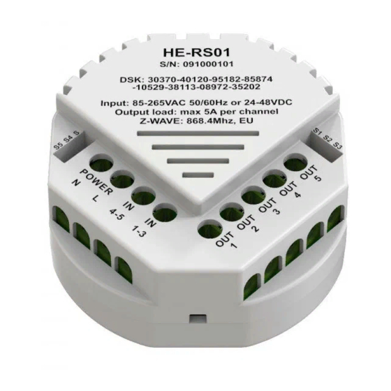
- Page 1 RELAY SWITCH QUINTO HE-RS01 USER MANUAL for Hardware v.76 & Firmware v.1.2...
-
Page 2: Table Of Contents
Installation ..................................4 Disassembly ..................................5 Factory Reset (RES) ................................ 5 Z-Wave Network ................................5 Adding HE-RS01 to a Z-Wave network ........................5 Removing HE-RS01 from a Z-Wave network ......................6 Security ..................................6 SmartStart ................................... 6 Firmware OTA Update ..............................6 Z-Wave Plus v2 Specifications ............................ -
Page 3: Overview
Z-Wave™ network. Thanks to the HE-RS01 five-channel relays it can manage up to five On/Off devices, or three On/Off devices and one two-direction motors, or one On/Off device and two two-direction motors. It has two independent inputs for relay channels which allow it to control systems with different power sources or to use relay outputs as dry contacts. -
Page 4: Functions & Features
OTA (Over The Air) encrypted firmware update Installation HELTUN recommends the HE-RS01 relay switch be installed by a licensed electrician in a manner that conforms to local regulations and building codes. Provide these instructions to the licensed electrician who is installing the HE-RS01. -
Page 5: Disassembly
1. Ensure the HE-RS01 is Powered On and the LED indicator blinks red slowly (i.e. it is excluded) 2. Start the Inclusion mode from the gateway/controller 3. To start the inclusion process on the HE-RS01, double-press the service button on the device (with no more than a one-second interval between presses). -
Page 6: Removing He-Rs01 From A Z-Wave Network
Removing from Z-Wave network To remove the HE-RS01 from a Z-Wave Network (i.e. “Exclusion”), do the following: 1. Ensure the HE-RS01 is Powered On and the LED indicator is slowly blinking green (i.e. it is included in a Z-Wave network). -
Page 7: Z-Wave Plus V2 Specifications
Import [0x01] Associations Association enables the HE-RS01 to control other Z-Wave devices over the network. The HE-RS01 has 6 Endpoints and 16 Association Groups. Each Association Group (except group 1) may include five other devices from different brands and/or manufacturers. -
Page 8: Gateway Compatibility Requirement
Note: Fibaro Home Center 2: In order to enable correct communications between a Fibaro Gateway/Controller and the HE-RS01, the lifeline association should be configured as a “multi-channel association.” Make sure that only the Multi-channel association check box is selected under Device > Settings > Advanced > Setting Association > Group1 tab (lifeline). -
Page 9: Operation
If the HE-RS01 is associated with a Z-Wave gateway, the scene controller and five binary switches will appear. The scene controller indicates which external input was pressed, held, or released and allows the running of scenes on the Z-Wave gateway. -
Page 10: Settings (Available Through Z-Wave Network)
HE-RS01 corresponding output was in an ON state. Using your connected device’s power consumption specification (see associated owner’s manual), set the load in Watts for: “OUT-1” in Parameters 12, “OUT-2” in Parameter 13, “OUT-3” in Parameter 14, “OUT-4” in the Parameter 15, and “OUT-5” in Parameter 16. - Page 11 23-40 Reserved by the manufacturer 1 byte Hold control mode for input S1 0, 1, 2, 3, 4 1 byte Hold control mode for input S2 0, 1, 2, 3, 4 1 byte Hold control mode for input S3 0, 1, 2, 3, 4 1 byte Hold control mode for input S4 0, 1, 2, 3, 4...
-
Page 12: Z-Wave Frequency
Parameter 01 – Frequency Region The HE-RS01 has Z-Wave 700 series chip inside which allows to use the device in different Z-Wave frequencies. If there is a need to use the device in the frequency different from the factory default, change the value of this Parameter according to the frequency list below. -
Page 13: Hardware & Software Versions
Parameter 19 – Time Correction by Main Controller If this Parameter value = 1 and the HE-RS01 is connected to a Z-Wave gateway, the HE-RS01 time and day will be periodically polled and corrected from the gateway. To switch off auto-correction set the Parameter value to 0. The factory default value is 1. -
Page 14: Buttons Mode
Buttons Mode Parameters 41-45 – Hold Control Mode for external inputs S1-S5 (correspondingly) 0 – Hold function is disabled 1 – Operate like click (Parameters 51 - 55) 2 – When the button on switch connected to external input is held, (key closed) the relay output state is ON, as soon as the button is released (key opened) the relay output state changes to OFF (momentary switch). -
Page 15: Scenarios
Note: In this mode, both relays cannot be switched ON at the same time (i.e. simultaneously). Note: Switching OFF one relay will always operate before switching ON another relay to prevent both relays from being ON at the same time. Note: Two groups of inverse relays can be specified, one group in Parameter 101, another group in Parameter 102. - Page 16 has been held for more than one second. They are useful options for controlling dimmers or roller shutter devices in the following three ways: “0” – On each hold event, “UP (brighten)” and “DOWN (dim)” command will be alternately sent to associated devices. “1”...
-
Page 17: Limited Warranty
HELTUN, at HELTUN's option, shall either repair or replace the defective product. If the product is defective, (i) return it with dated proof of purchase to the place it was purchased; or (ii) contact HELTUN Customer Care by email at support@heltun.com.
Need help?
Do you have a question about the HE-RS01 and is the answer not in the manual?
Questions and answers