Table of Contents
Advertisement
Quick Links
Advertisement
Table of Contents

Related Manuals for Heltun QUINTO HE-TPS05


Summary of Contents for Heltun QUINTO HE-TPS05
- Page 1 TOUCH PANEL SWITCH QUINTO HE-TPS05 USER MANUAL V1.0...
-
Page 2: Table Of Contents
Table of Contents Overview ................................... 3 Technical Specifications ..............................3 Functions & Features ................................ 4 Installation ..................................5 Disassembly ..................................6 Touch Panel Operation ..............................6 Scenarios ................................... 7 Factory Reset (RES) ................................7 Power and Energy Consumption............................7 Resetting Cumulative Consumption Memory ......................7 Z-Wave Network ................................ -
Page 3: Overview
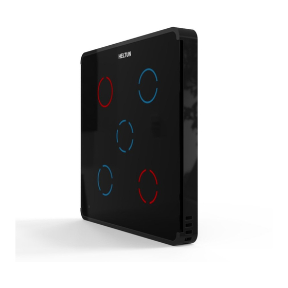
Overview This is the user manual for the HELTUN HE-TPS05 Advanced Programmable Touch Panel Switch. The HE-TPS05 brings ‘Impossibly Smart’ capabilities to your home lighting, electric outlets, or motorized blinds, door locks, gates, and valves. It replaces an existing in-wall switch and brings over-the-Internet monitoring, control, and advanced programmability to five connected devices. -
Page 4: Functions & Features
• Relay lifetime: 100.000 switches • Internal ambient light sensor • Internal temperature sensor Measurement range: –30°C to +80°C Accuracy: ±0.5°C • Internal humidity sensor Measurement range: 0% to 80%RH Accuracy: ±3.0%RH • IP class: IP21 • Z-Wave Plus V2 SDK: V7.11 •... -
Page 5: Installation
• Loads: connect the required loads to the relay output terminals labeled “OUT-1”, “OUT-2”, “OUT-3”, “OUT-4”, “OUT-5”. Note: HELTUN recommends installing cord terminals (electric wire ferrule) on the ends of wires before connecting them to the HE-TPS05 outputs (various colors terminals are included in the packaging). -
Page 6: Disassembly
Disassembly 1. ENSURE POWER IS SWITCHED OFF at the main circuit breaker AND ALL BUTTON BACKLIGHTS ARE OFF. To remove the HE-TPS05 touch panel unit, grasp firmly at the bottom and pull backwards while tilting outwards until all tabs disconnect. 3. -
Page 7: Scenarios
The HE-TPS05 may be operated in any Z-Wave network with other Z-Wave-certified devices from other manufacturers. The HELTUN HE-TPS05 will act as a ‘repeater’ (i.e. ‘range extender’) for other devices regardless of manufacturer or brand to increase the reliability of the overall network. -
Page 8: Removing He-Tps05 From A Z-Wave Network
Start the process from the Z-Wave gateway/controller. Download the latest firmware that corresponds to the HE-TPS05 (see https://www.heltun.com/support Set the main controller in Firmware OTA (“over-the-air”) Update Mode (see the gateway/controller manual). As soon as the Firmware update begins, all buttons will sequentially blink blue-red (this will take a few minutes). - Page 9 EndPoint 0 Groups: The Root Device (EndPoint 0) of HE-TPS05 has 21 association groups Group 1 – “Lifeline”: reports state of the device and is used to communicate with the Z-Wave gateway. This group supports one Node. Note: It is not recommended to modify this group. Note: For correct operating in Fibaro gateways the Single Channel Association should be removed from the device LifeLine (EndPoint 0 Group 1).
-
Page 10: Gateway Compatibility Requirement
EndPoints 1-10 Groups: Group 1 – “Lifeline”: reports state of the device and used to communicate with the Z-Wave gateway. The group supports one Node. Note: It is not recommended to modify this group. Group 2 – “Basic Set”: Is used to send Basic Set ON (value 255) and Basic Set OFF (value 0) commands to the associated devices. -
Page 11: Z-Wave Plus V2 Specifications
Z-Wave Plus v2 Specifications Generic Device Class: GENERIC_TYPE_WALL_CONTROLLER Specific Device Class: SPECIFIC_TYPE_NOT_USED Supported Command Classes Command Class Version Required Security Class Z-Wave Plus Info none Association highest granted (S2 Authenticated, S2 Unauthenticated or S0) Association Group Info highest granted (S2 Authenticated, S2 Unauthenticated or S0) Multi Channel Association highest granted (S2 Authenticated, S2 Unauthenticated or S0) Multi Channel... -
Page 12: Sensor Configuration
Note: The HE-TPS05 sensor is very sensitive to ambient humidity changes and can often detect shifts as small as ±1%. Therefore, HELTUN recommends setting this parameter at 2% or above, to reduce the data transfer load across your Z-Wave network. -
Page 13: Backlight
Parameter 11 – Temperature Sensor Calibration This parameter defines the offset value for the air temperature sensor. If the internal temperature sensor is not correctly calibrated, then it may be manually calibrated by adjusting the values up to +/- 10.0°C. This offset value will be added or subtracted from the internal air temperature sensor reading. - Page 14 5 – Timer: On>Off Mode: Relay output switches to ON state (contacts are closed) then after a specified time switches back to OFF state (contacts are open). The time is specified in parameters 35-39. 6 – Timer: OFF>ON Mode: Relay output switches to OFF state (contacts are open) then after a specified time switches back to ON state (contacts are closed).
- Page 15 Note: The logic will implement the operation when the sensor value crosses the value in the Parameter. Meaning, that if the logic Switches on the relay and you manually switch it Off, the relay will switch On next time when the value crosses the set parameter.
-
Page 16: Factory Default Parameters
Factory Default Parameters Default Available Number Size Name Description Value Values 1 byte TIME CORRECTION Time correction by controller 0, 1 1 byte WEEKDAY Week Day 1, 2, 3, 4, 5, 6, 7 1 byte HOUR Time Hour 0 to 23 1 byte MINUTE Time Minute 0 to 59... - Page 17 0, 12, 13, 14, 15, 21, 23, 24, 25, 1 byte RELAY INVERSE GROUP2 Group 2 relay inverse mode 31, 32, 34, 35, 41, 42, 43, 45, 51, 52, 53, 54 0, 10000000 to 4 bytes RELAY CONTROL SCENARIO1 Relays control by sensors Group 1 53112359 0, 10000000 to 4 bytes RELAY CONTROL SCENARIO2...
-
Page 18: Limited Warranty
HELTUN warrants this product to be free from defects in workmanship or materials, under normal use and service, for a period of one (1) year from the date of purchase by the consumer ("Warranty Period"). HELTUN will extend this Warranty Period to three (3) years from the date of consumer purchase for any consumer who registers their warranty with HELTUN at this website page: bonus.heltun.com.
Need help?
Do you have a question about the QUINTO HE-TPS05 and is the answer not in the manual?
Questions and answers