Table of Contents
Advertisement
Quick Links
NuMaker-LoRaD470-M252
NuMaker-LoRaD868-M252
NuMaker-LoRaD915-M252
Evaluation Board for LoRa Ecosystem Device Design
The information described in this document is the exclusive intellectual property of
Nuvoton Technology Corporation and shall not be reproduced without permission from Nuvoton.
Nuvoton is providing this document only for reference purposes of NuMicro microcontroller based system
design. Nuvoton assumes no responsibility for errors or omissions.
All data and specifications are subject to change without notice.
For additional information or questions, please contact: Nuvoton Technology Corporation.
Dec. 21, 2020
NuMaker-LoRaD470/868/915-M252
Based on Arm
User Manual
www.nuvoton.com
Page 1 of 31
NuMicro
®
Family
®
Cortex
®
-M23
Rev 1.00
Advertisement
Table of Contents

Related Manuals for Nuvoton NuMaker-LoRaD470-M252


Summary of Contents for Nuvoton NuMaker-LoRaD470-M252
- Page 1 The information described in this document is the exclusive intellectual property of Nuvoton Technology Corporation and shall not be reproduced without permission from Nuvoton. Nuvoton is providing this document only for reference purposes of NuMicro microcontroller based system design. Nuvoton assumes no responsibility for errors or omissions.
-
Page 2: Table Of Contents
NuMaker-LoRaD470/868/915-M252 Table of Contents 1 OVERVIEW ...................... 5 2 FEATURES ...................... 6 3 HARDWARE CONFIGURATION ..............7 3.1 Front View ........................7 3.2 Rear View ........................8 3.3 Extension Connectors ....................9 3.3.1 Pin Assignment for Extension Connectors ..............9 3.3.2 Arduino UNO Compatible Extension Connectors ............ - Page 3 NuMaker-LoRaD470/868/915-M252 List of Figures Figure 1-1 NuMaker-LoRaD-M252 Evaluation Board ..............5 Figure 3-1 Front View of NuMaker-LoRaD-M252 ................7 Figure 3-2 Rear View of NuMaker-LoRaD-M252 ................8 Figure 3-3 M252KG6AE Extension Connectors ................9 Figure 3-4 Arduino UNO Compatible Extension Connectors ............14 Figure 3-5 External Power Supply Sources on Nu-Link2-Me ............
- Page 4 NuMaker-LoRaD470/868/915-M252 List of Tables Table 3-1 Extension Connectors ...................... 9 Table 3-2 M252KG6AE Full-pin Extension Connectors and GPIO Function List ......13 Table 3-3 Arduino UNO Extension Connectors and M252KG6AE Mapping GPIO List ....15 Table 3-4 On-board LoRa Module and M252KG6AE GPIO Function List ........16 Table 3-5 Vin Power Source ......................
-
Page 5: Overview
M252KG6AE, LoRa module, the Arduino UNO compatible headers and the capability of adopting multiple power supplies. Furthermore, the Nuvoton- designed ammeter connector can measure the power consumption instantly, which is essential for the LoRa prototype evaluation. -
Page 6: Features
NuMaker-LoRaD470/868/915-M252 FEATURES NuMicro M252KG6AE microcontroller with functions compatible with: M252KG6AE – M251KG6AE – M252SG6AE – M251SG6AE – M252LG6AE – M251LG6AE – On-board LoRa module: RYLR890 for 868/915 MHz (Order Number: NK-LDMM252/NK-LDHM252) – RYLR400 for 470 MHz (Order Number: NK-LDLM252) –... -
Page 7: Hardware Configuration
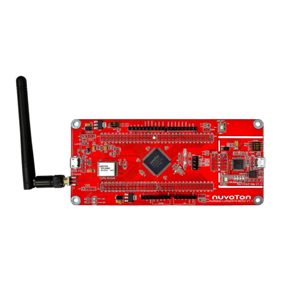
NuMaker-LoRaD470/868/915-M252 HARDWARE CONFIGURATION Front View Arduino UNO Compatible Extension Switch Connector Reset Button External V Connector Ammeter VCOM Switch External V Connector ICE USB Connector USB FS Connector ICE Chip: M48SSIDAE LoRa Module ICE Status LED LoRa Antenna Off-line Program Button External V Connector PB14 LED... -
Page 8: Rear View
MCUVCC Power Switch (ICEJPR1) – ICEVCC Power Switch (ICEJPR2) – ICEVCC Power Switch MCUVCC Power Switch M252SG6AE M252LG6AE M251KG6AE M251SG6AE M251LG6AE www.nuvoton.com/board/NuMaker-LoRaD470-M252 Order No. NK-LDLM252 Figure 3-2 Rear View of NuMaker-LoRaD-M252 Dec. 21, 2020 Page 8 of 31 Rev 1.00... -
Page 9: Extension Connectors
NuMaker-LoRaD470/868/915-M252 Extension Connectors Table 3-1 presents the extension connectors. Connector Description JP3, JP4, JP5 and JP6 Full pins extension connectors on the NuMaker-LoRaD-M252. NU1, NU2, NU3 and Arduino UNO compatible pins on the NuMaker-LoRaD-M252. Table 3-1 Extension Connectors 3.3.1 Pin Assignment for Extension Connectors The NuMaker-LoRaD-M252 provides the M252KG6AE onboard and extension connectors (JP3, JP4, JP5 and JP6). - Page 10 NuMaker-LoRaD470/868/915-M252 M252KG6AE Header Pin No. Function PB.5/EADC0_CH5/ACMP1_N/EBI_ADR0/I2C0_SCL/USCI1_CTL0/SC0_CLK/PWM0_CH0/PSIO0_ JP3.1 CH4/UART2_TXD/TM0/INT0 PB.4/EADC0_CH4/ACMP1_P1/EBI_ADR1/I2C0_SDA/USCI1_CTL1/SC0_DAT/PWM0_CH1/PSIO0 JP3.2 _CH5/UART2_RXD/TM1/INT1 PB.3/EADC0_CH3/ACMP0_N/EBI_ADR2/I2C1_SCL/UART1_TXD/USCI1_DAT1/SC0_RST/PWM0_ JP3.3 CH2/PSIO0_CH6/PWM0_BRAKE0/TM2/INT2 PB.2/EADC0_CH2/ACMP0_P1/OPA0_O/EBI_ADR3/I2C1_SDA/UART1_RXD/USCI1_DAT0/SC0_P JP3.4 WR/PWM0_CH3/PSIO0_CH7/TM3/INT3 JP3.5 PC.12/EBI_ADR4/UART0_TXD/I2C0_SCL/SC0_nCD/PWM1_CH0/ACMP0_O JP3.6 PC.11/EBI_ADR5/UART0_RXD/I2C0_SDA/PWM1_CH1/ACMP1_O JP3.7 PC.10/EBI_ADR6/PWM1_CH2 JP3.8 PC.9/EBI_ADR7/PWM1_CH3 PB.1/EADC0_CH1/OPA0_N/EBI_ADR8/UART2_TXD/USCI1_CLK/I2C1_SCL/QSPI0_MISO1/PWM JP3.9 0_CH4/PWM1_CH4/PWM0_BRAKE0 PB.0/EADC0_CH0/OPA0_P/EBI_ADR9/UART2_RXD/SPI0_I2SMCLK/I2C1_SDA/QSPI0_MOSI1/P JP3.10 WM0_CH5/PWM1_CH5/PWM0_BRAKE1 JP3.11 JP3.12 JP3.13 PA.11/ACMP0_P0/EBI_nRD/USCI0_CLK/BPWM0_CH0/TM0_EXT JP3.14 PA.10/ACMP1_P0/EBI_nWR/USCI0_DAT0/BPWM0_CH1/TM1_EXT/DAC0_ST JP3.15 PA.9/EBI_MCLK/USCI0_DAT1/UART1_TXD/BPWM0_CH2/TM2_EXT JP3.16 PA.8/EBI_ALE/USCI0_CTL1/UART1_RXD/BPWM0_CH3/TM3_EXT/INT4 JP3.17...
- Page 11 NuMaker-LoRaD470/868/915-M252 M252KG6AE Header Pin No. Function JP5.1 JP5.2 JP5.3 JP5.4 JP5.5 PF.3/EBI_nCS0/UART0_TXD/I2C0_SCL/XT1_IN/BPWM1_CH0 JP5.6 PF.2/EBI_nCS1/UART0_RXD/I2C0_SDA/QSPI0_CLK/XT1_OUT/BPWM1_CH1 JP5.7 JP5.8 JP5.9 PE.8/EBI_ADR10/USCI1_CTL1/UART2_TXD/PWM0_CH0/PWM0_BRAKE0 JP5.10 PE.9/EBI_ADR11/USCI1_CTL0/UART2_RXD/PWM0_CH1/PWM0_BRAKE1 JP5.11 PE.10/EBI_ADR12/USCI1_DAT0/PWM0_CH2/PWM1_BRAKE0 JP5.12 PE.11/EBI_ADR13/USCI1_DAT1/UART1_nCTS/PWM0_CH3/PWM1_BRAKE1 JP5.13 PE.12/EBI_ADR14/USCI1_CLK/UART1_nRTS/PWM0_CH4 JP5.14 PE.13/EBI_ADR15/I2C0_SCL/UART1_TXD/PWM0_CH5/PWM1_CH0/BPWM1_CH5 JP5.15 PC.8/EBI_ADR16/I2C0_SDA/UART1_RXD/PWM1_CH1/BPWM1_CH4 JP5.16 PC.7/EBI_AD9/UART0_nCTS/I2C1_SMBAL/PWM1_CH2/BPWM1_CH0/TM0/INT3 JP5.17 PC.6/EBI_AD8/UART0_nRTS/I2C1_SMBSUS/PWM1_CH3/BPWM1_CH1/TM1/INT2 JP5.18 PA.7/EBI_AD7/UART0_TXD/I2C1_SCL/PWM1_CH4/BPWM1_CH2/ACMP0_WLAT/TM2/INT1 JP5.19 PA.6/EBI_AD6/UART0_RXD/I2C1_SDA/PWM1_CH5/BPWM1_CH3/ACMP1_WLAT/TM3/INT0 JP5.20 JP5.21 JP5.22 PD.15/PSIO0_CH7/PWM0_CH5/TM3/INT1 JP5.23...
- Page 12 NuMaker-LoRaD470/868/915-M252 M252KG6AE Header Pin No. Function Note: It is recommended to use 100 kΩ pull-up resistor on ICE_DAT pin. PF.1/UART1_RXD/I2C1_SDA/UART0_RXD/BPWM1_CH1/ICE_CLK JP4.2 Note: It is recommended to use 100 kΩ pull-up resistor on ICE_CLK pin. JP4.3 PD.9/EBI_AD7/UART2_nCTS/PSIO0_CH2 JP4.4 PD.8/EBI_AD6/UART2_nRTS/PSIO0_CH3 JP4.5 PC.5/EBI_AD5/QSPI0_MISO1/UART2_TXD/I2C1_SCL/PWM1_CH0/PSIO0_CH0 JP4.6 PC.4/EBI_AD4/QSPI0_MOSI1/UART2_RXD/I2C1_SDA/PWM1_CH1/USCI2_CTL1/PSIO0_CH1 JP4.7...
-
Page 13: Table 3-2 M252Kg6Ae Full-Pin Extension Connectors And Gpio Function List
NuMaker-LoRaD470/868/915-M252 M252KG6AE Header Pin No. Function JP6.3 PE.5/EBI_nRD/SC0_PWR/USCI0_CTL1/PSIO0_CH2/PWM0_CH2/BPWM0_CH3 JP6.4 PE.4/EBI_nWR/SC0_RST/USCI0_DAT1/PSIO0_CH3/PWM0_CH3/BPWM0_CH2 JP6.5 PE.3/EBI_MCLK/SC0_DAT/USCI0_DAT0/PWM0_CH4/BPWM0_CH1 JP6.6 PE.2/EBI_ALE/SC0_CLK/USCI0_CLK/USCI2_CTL0/PWM0_CH5/BPWM0_CH0 JP6.7 JP6.8 JP6.9 PE.1/EBI_AD10/QSPI0_MISO0/I2C1_SCL/USCI2_DAT1 JP6.10 PE.0/EBI_AD11/QSPI0_MOSI0/I2C1_SDA/USCI2_DAT0 JP6.11 JP6.12 JP6.13 JP6.14 JP6.15 JP6.16 JP6.17 LDO_CAP JP6.18 JP6.19 PC.14/EBI_AD11/SPI0_I2SMCLK/USCI0_CTL0/QSPI0_CLK/USCI2_CLK/TM1 PB.15/EADC0_CH15/EBI_AD12/SPI0_SS/USCI0_CTL1/UART0_nCTS/PSIO0_CH0/PWM1_CH0/T JP6.20 M0_EXT/PWM0_BRAKE1 PB.14/EADC0_CH14/EBI_AD13/SPI0_CLK/USCI0_DAT1/UART0_nRTS/PSIO0_CH1/PWM1_CH1/ JP6.21 TM1_EXT/CLKO PB.13/EADC0_CH13/ACMP0_P3/ACMP1_P3/EBI_AD14/SPI0_MISO/USCI0_DAT0/UART0_TXD/P JP6.22 SIO0_CH2/PWM1_CH2/TM2_EXT PB.12/EADC0_CH12/DAC0_OUT/ACMP0_P2/ACMP1_P2/EBI_AD15/SPI0_MOSI/USCI0_CLK/UA JP6.23 RT0_RXD/PSIO0_CH3/PWM1_CH3/TM3_EXT... -
Page 14: 3.3.2 Arduino Uno Compatible Extension Connectors
NuMaker-LoRaD470/868/915-M252 3.3.2 Arduino UNO Compatible Extension Connectors Figure 3-4 shows the Arduino UNO compatible extension connectors. MOSI PA.10 PB.15 USCI0_DAT0 MISO RESET PA.9 PA.11 nRESET PA.8 USCI0_DAT1 USCI0_CLK PB.1 EADC0_CH1 I2C1_SCL UART2_TXD UART1_RXD PWM0_CH3 PB.2 UART1_TXD PWM0_CH2 PB.3 PB.0 EADC0_CH0 I2C1_SDA UART2_RXD I2C1_SDA... -
Page 15: Table 3-3 Arduino Uno Extension Connectors And M252Kg6Ae Mapping Gpio List
NuMaker-LoRaD470/868/915-M252 NuMaker-LoRaD-M252 NuMaker-LoRaD-M252 Header Header Compatible to Compatible to GPIO Pin of M252 GPIO Pin of M252 Arduino UNO Arduino UNO NU3.1 PB.2 NU2.6 PB.1 NU3.2 PB.3 NU2.5 PB.0 NU3.3 PC.4 NU2.4 PB.4 NU3.4 PC.5 NU2.3 PB.5 NU3.5 PC.3 NU2.2 PB.6 NU3.6 PC.2... -
Page 16: Pin Assignment For On-Board Lora Module
NuMaker-LoRaD470/868/915-M252 Pin Assignment for On-board LoRa Module The NuMaker-LoRaD-M252 provides an on-board LoRa module. Table 3-1 shows the mapping GPIO list. NuMaker-LoRaD-M252 On-board LoRa Module Function of GPIO Pin GPIO Pin of M252KG6AE MISO SPI0_MISO PD.1 MOSI SPI0_MOSI PD.0 SPI0_CLK PD.2 SPI0_SS PD.3... -
Page 17: Power Sources
NuMaker-LoRaD470/868/915-M252 3.5.2 5 V Power Sources Table 3-6 presents the 5 V power sources. Net Name in Connector Description Schematic ICE USB connector supplies 5 V power from PC to ICEJ3 USB_HS_VBUS M252 target board and Nu-Link2-Me. USB connector on NuMaker-LoRaD-M252 supplies 5 V USB_VBUS power from PC to M252 target board and Nu-Link2-Me. -
Page 18: Power Connectors
NuMaker-LoRaD470/868/915-M252 3.5.5 Power Connectors Table 3-9 presents the power connectors. Connector Description connector on the NuMaker-LoRaD-M252. Note: LoRa module operating voltage range is from 1.8 V to 3.6 V. connector on the NuMaker-LoRaD-M252. Table 3-9 Power Connectors 3.5.6 USB Connectors Table 3-10 presents the USB connectors. -
Page 19: Power Supply Models
NuMaker-LoRaD470/868/915-M252 3.5.8 Power Supply Models External Power Supply through Nu-Link2-Me to Target Chip The external power supply source on Nu-Link2-Me is shown in Figure 3-5. ICE USB Connector (ICEJ3) Nu-Link2-Me NuMaker-RoLaD470-M252 V1.1 Figure 3-5 External Power Supply Sources on Nu-Link2-Me To use ICEJ3 as external power supply source with Nu-Link2-Me, please follow the steps below: Solder the resistor on ICEJPR1 (MCUVCC) depending on the target chip operating voltage. -
Page 20: Figure 3-6 External Power Supply Sources On M252 Target Board
NuMaker-LoRaD470/868/915-M252 External Power Supply through M252 Target Board to Target Chip The external power supply sources on M252 target board are shown in Figure 3-6. External V Connector (JP1) USB Power Connector (J2) External V Connector (JP2) NuMaker-RoLaD470-M252 V1.1 NU1 pin8 (Vin) Figure 3-6 External Power Supply Sources on M252 Target Board To use Vin or J2 as external power supply source, please follow the steps below: Switch the SW2 depending on the target chip operating voltage. -
Page 21: Figure 3-7 Detach The Nu-Link2-Me From Numaker-Lorad-M252
NuMaker-LoRaD470/868/915-M252 External V Connector (JP1) USB Power Connector (J2) " External V Connector (JP2) Separate Nu-Link2-Me NuMaker-RoLaD-M252 V1.1 NU1 pin8 (Vin) Figure 3-7 Detach the Nu-Link2-Me from NuMaker-LoRaD-M252 Table 3-13 presents all power models when supplies external power through M252 target board. The M252 target board external power sources are highlighted in yellow. -
Page 22: External Reference Voltage Connector
NuMaker-LoRaD470/868/915-M252 External Reference Voltage Connector Table 3-17 presents the external reference voltage connector. Connector Description Connector for user to connect to the external reference voltage pin of the VREF1 target chip. User needs to remove the L5 ferrite bead. Table 3-14 External Reference Voltage Connector Voltage Adjustable Interface (VAI) Connector Table 3-15 presents the voltage adjustable interface connector. -
Page 23: 3.10 Push Buttons
NuMaker-LoRaD470/868/915-M252 Remove the R16 Resistor NuMaker-RoLaD470-M252 V1.1 Figure 3-8 Wiring between Ammeter Connector and Ammeter 3.10 Push Buttons Table 3-18 presents the push buttons. Component Description ICESW1 Offline program button to start offline ICP programming the target chip. Reset button to reset the target chip. Table 3-18 Push-Buttons 3.11 LEDs Table 3-19 presents the LEDs. -
Page 24: 3.12 Nu-Link2-Me
NuMaker-LoRaD470/868/915-M252 3.12 Nu-Link2-Me The Nu-Link2-Me is an attached on-board debugger and programmer. The Nu-Link2-Me supports on- chip debugging, online and offline ICP programming through SWD interface. The Nu-Link2-Me also supports virtual COM port (VCOM) for printing debug messages on PC. Besides, the programming status could be shown on the built-in LEDs. -
Page 25: Numaker-Lorad-M252 Schematics
NuMaker-LoRaD470/868/915-M252 NUMAKER-LORAD-M252 SCHEMATICS Nu-Link2-Me Figure 4-1 shows the Nu-Link2-Me circuit. 3.3V ICER1 O f f - page C onnect or 200 1% USB_HS_CAP R0603 ICE5V ICEC1 ICEC2 ICE5V 0.1u MCUVCC_DIODE C0603 C0603 MCUVCC_DIODE SWDH_DAT TICEDAT SWDH_CLK TICECLK SWDH_RST# TICERST ICE_RX_S MCU_TX ICE_TX_S MCU_RX... -
Page 26: M252 Target Board
NuMaker-LoRaD470/868/915-M252 M252 Target Board Figure 4-2 shows the M252 target board circuit. P1 - P32 P65 - P96 PF0_ICE_DAT PB5_NU2_A2 TICEDAT PF1_ICE_CLK PB4_NU2_A3 TICECLK PB3_NU3_D1/TX PB2_NU3_D0/RX PC12 PC5_NU3_D3 PC11 PC4_NU3_D2 PC10 PC3_NU3_D4 PC2_NU3_D5 PB1_NU2_A5/SCL/TX PC1_NU4_SCL PB0_NU2_A4/SDA/RX PC0_NU4_SDA nRESET PE.15/EBI_AD9/UART2_RXD/PSIO0_CH1 VDD_3 VDD_4 PE.14/EBI_AD8/UART2_TXD/PSIO0_CH0 VDD_MCU... -
Page 27: Extension Connectors
NuMaker-LoRaD470/868/915-M252 Extension Connectors Figure 4-3 shows extension connectors of NuMaker-LoRaD-M252. P1 - P32 P65 - P96 PB5_NU2_A2 PB4_NU2_A3 TICEDAT TICECLK PC1_NU4_SCL I2C_SCL PB3_NU3_D1/TX PB2_NU3_D0/RX PC0_NU4_SDA I2C_SDA PC12 PC11 PC5_NU3_D3 PC4_NU3_D2 VREF VREF PC10 PC3_NU3_D4 PC2_NU3_D5 MCUVCC_DIODE PB1_NU2_A5/SCL/TX PB0_NU2_A4/SDA/RX PC1_NU4_SCL PC0_NU4_SDA TICERST PA2_NU3_D13/CLK MCU_RESET... -
Page 28: Lora Module
NuMaker-LoRaD470/868/915-M252 LoRa Module Figure 4-3 shows the LoRa Module circuit. RYLR890 and RYLR400 support the same footprint, but different frequency band range. Before developing LoRa application at NuMaker-LoRaD-M252, please refer the following order number to select LoRa frequency band range. ... -
Page 29: Pcb Placement
NuMaker-LoRaD470/868/915-M252 PCB Placement Figure 4-5 and Figure 4-6 show the front and rear placement of NuMaker-LoRaD-M252. Figure 4-5 Front Placement Figure 4-6 Rear Placement Dec. 21, 2020 Page 29 of 31 Rev 1.00... -
Page 30: Revision History
NuMaker-LoRaD470/868/915-M252 REVISION HISTORY Date Revision Description 2020.12.21 1.00 Initial version Dec. 21, 2020 Page 30 of 31 Rev 1.00... - Page 31 NuMaker-LoRaD470/868/915-M252 Important Notice Nuvoton Products are neither intended nor warranted for usage in systems or equipment, any malfunction or failure of which may cause loss of human life, bodily injury or severe property damage. Such applications are deemed, “Insecure Usage”.
Need help?
Do you have a question about the NuMaker-LoRaD470-M252 and is the answer not in the manual?
Questions and answers